KADIR HAS UNIVERSITY
GRADUATE SCHOOL OF SCIENCE AND ENGINEERING
FEMTOCELL DESIGN FOR DATA COMMUNICATIONS IN MOBILE
NETWORKS
TEZCAN ÇOĞALAN
Te zc an ÇOĞA LA N M.S . The sis 20 13 S tudent’ s F ull Na me P h.D. (or M.S . or M.A .) The sis 20 11
FEMTOCELL DESIGN FOR DATA COMMUNICATIONS IN MOBILE
NETWORKS
TEZCAN ÇOĞALAN
Submitted to the Graduate School of Science and Engineering in partial fulfillment of the requirements for the degree of
Master of Science in
Electronics Engineering
KADIR HAS UNIVERSITY May, 2013
KADIR HAS UNIVERSITY GRADUATE SCHOOL OF SCIENCE AND ENGINEERING
FEMTOCELL DESIGN FOR DATA COMMUNICATIONS IN MOBILE NETWORKS
TEZCAN ÇOĞALAN
APPROVED BY:
Prof. Erdal Panayırcı (Kadir Has University) ______________ (Thesis Supervisor)
Asst. Prof. Serhat Erküçük (Kadir Has University) ______________
Prof. Hakan Ali Çırpan (Istanbul Technical University) ______________
APPROVAL DATE: Day/Month/Year AP PE ND IX C APPENDIX B APPENDIX B
i
FEMTOCELL DESIGN FOR DATA COMMUNICATIONS IN
MOBILE NETWORKS
Abstract
Developing smart phone technologies and their applications cause increasing demand on high data rates. Users interest with social network platforms and they would like to share photos and videos. According to researches and telecom company reports about usage area of mobile data transfers, voice and data traffic are generated at indoor like home, office, restaurant etc. Mobile operators work out for supplying high data rates and increase their capacity and coverage area for indoor users who encountered with weak signal power. The one of the main works about that is decreasing the distance of mobile station and base station. Due to the decreasing of this distance, users have high data rate and in spite of the increasing number of base stations, operators have better coverage area and increase their capacity. Femtocell technology, which is also called home base stations, provides high data transfer rates and better coverage area for limited number of subscribers at indoor. Resulting of spectrum scarcity, operators have to share their spectrum with femtocells and they have to manage interference of existent systems and femtocells. The most important interference management approach is power control. In power control technique, transmit power consumption from mobile stations are arranged for mitigation of interference. In this thesis, game theoretic utility-based adaptive power control algorithm for uplink of femtocell networks is performed for mitigation of interference in two different ways. The first one is allocation of femtocell interference threshold in randomly activated femtocell base stations in a known macrocell coverage area and the second one is adaptation of the power of the femtocell users for mitigating total interference from femtocell users at the macrocell base station. Accordingly, we consider two different pricing schemes which are
centralized pricing and de-centralized pricing for updating the power level at mobile
station. In addition, we examined two different technologies which are frequency division multiple access (FDMA) and code DMA (CDMA). The results show that each active user at network could reach the given signal to interference plus noise AP
PE ND IX C
ii
ratio (SINR) threshold value with iterative power control algorithm and macrocell base station encountered with given interference threshold value with power control and user removal algorithms.
iii
MOBİL ŞEBEKELERDE VERİ İLETİMİ İÇİN FEMTO HÜCRE
TASARIMI
Özet
Gelişmekte olan akıllı telefon teknolojisi ve uygulamaları, kullanıcıların daha fazla veriye daha hızlı ulaşma ihtiyacına sevk etmektedir. Kullanıcıların sosyal paylaşım sitelerine olan ilgisi, bu siteler aracılığı ile fotoğraf ve video paylaşımı, başkaları tarafından paylaşılmış fotoğraf ve yüksek çözünürlükteki videoların mobil aygıtlarda görüntülenmek istenmesi ve bütün bunların çok kısa sürede olup kullanılan aygıtın pil ömrünün uzun olması beklenmektedir. Literatürde yapılmış araştırmalar ve telekomünikasyon servis sağlayıcılarının raporlarına göre, bu isteklerin büyük çoğunluğu kapalı yaşam alanları olan ev, ofis, restoran vb. yerlerde gerçekleşmektedir. Sinyal gücünün zayıf olduğu bu alanlarda kullanıcılara yüksek hızlarda veri sağlayabilmek için operatörler kapsama alanlarını ve kapasitelerini arttırmaya yönelik çalışmalar yapmaktadırlar. Bu çalışmaların başlıca olanı kullanıcı mobil istasyonu ile bağlı olduğu operatöre ait baz istasyonu arasındaki mesafeyi azaltarak veri hızını, baz istasyonu sayısının artmasıyla da mevcut kapasiteyi attırarak kullanıcıya istediği düzeyde hizmet sağlamaktır. Femto hücre olarak adlandırılan ve aynı zamanda ev baz istasyonu olarak da bilinen teknoloji, belirli sayıdaki kapalı alan kullanıcılarına yüksek hızlarda veri transferi ve operatöre daha iyi kapsama alanı sağlamaktadır. Spektrum kıtlığından dolayı operatörler bu teknolojiyi var olan spektrumları ile paylaşımlı olarak kullanırken, mevcut sistemleri ile girişimini iyi yönetmek zorundadır. Bunun için kullanılan girişim yönetimi tekniklerinden başlıca olanı güç kontrol tekniğidir. Güç kontrol tekniğinde, femto hücreye bağlı kullanıcılar kendi gücünü ağda bulunan diğer femto hücre kullanıcılarına ve makro baz istasyonlarına girişim yapmamak için belli bir eşik seviyesinde tutmalıdır. Bu çalışmada sinyal gücünün girişim ve gürültü gücüne oranı (SGGO) esaslı, makro hücre kapsama alanı içerisinde rastgele aktif olan femto hücre mobil istasyonları arasındaki girişimi aza indirmek amacıyla oyun teorisi kullanılan fayda fonksiyonu baz alınmış uyarlanabilir güç kontrol algoritması iki farklı açıdan incelenmiştir. İlk durumda, makro baz istasyonu tarafından femto AP
PE ND IX C
iv
kullanıcılarına rastgele olarak atanmış girişim eşik değerlerini ve ikinci durumda makro baz istasyonu için belirlenmiş toplam girişim eşik değerini sağlayacak olan femto hücre kullanıcılarının güçleri uyarlanabilir algoritma ile elde edilmek istenmiştir. Ayrıca femto hücre kullanıcılarının güçlerini güncellemeleri için gerekli girişim eder değerleri merkezi ve merkezi olmayan duyuru şemaları uygulanmıştır. Bunlara ek olarak frekans bölüşümlü çoklu erişim (FBÇE) ile kod (CBÇE) sistemleri karşılaştırılmıştır. Her bir aktif femto kullanıcısı kendisine atanmış SGGO eşik değerine tekrarlı güç güncellemesiyle, makro hücre de kendisine atanmış SGGO eşik değerini güç kontrolü ve kullanıcı çıkarma algoritması ile ulaşmıştır.
v
Acknowledgements
There are many people who helped to make my years at the graduate school most valuable. First, I deeply thank my thesis supervisor, Prof. Erdal PANAYIRCI who has supported me, not only for the thesis but also for every step of my graduate studies. Having the opportunity to work with him over the years was intellectually rewarding and fulfilling. His suggestions and problem solving experiences were invaluable during thesis study. I also thank Betül ALTINOK who contributed much to the development of this research starting from the early stages of my dissertation work and provided valuable contributions to the development of the system model.
Besides my supervisors, I would like to thank Asst. Prof. Serhat ERKÜÇÜK who was very supportive during my undergraduate and graduate studies. His experiences and opinions have important role of my future career plans. Also during my undergraduate and graduate assistantship of laboratory, I have learnt lots of things about teaching and grading ethics from him.
I would also like to thank to Department of Electronics Engineering of Kadir Has University professors and my graduate assistant friends.
The last but not least, I would like to thank my family. I am very grateful to them for leading me onto right path and teaching me many good things about life. Finally, I would like to thank Gökçen TÜRKEL who always has the right word of advice and knows how to make me laugh. Without her endless support, I could not finish this thesis.
This study was supported by the TBD (Informatics Association of Turkey) and TURKCELL with “Technology Leaders Graduate Scholarship Program”.
AP PE ND IX C APPENDIX B
vi
Table of Contents
Abstract i Özet iii Acknowledgements v Table of Contents viList of Figures vii
List of Symbols / Abbreviations viii
1. Introduction 1
2. General Introduction to Cellular Communications 7
2.1. 2nd Generation (GSM) Systems ... 7
2.1.1. Network Architecture... 9
2.2. 3rd Generation (UMTS) Systems ... 11
2.2.1. WCDMA ... 12
2.2.2. Radio Access Network Architecture ... 13
2.3. 4th Generation (LTE) Systems ... 15
2.3.1. OFDMA ... 16
2.3.2. SC-FDMA ... 18
2.3.3. System Architecture Evolution ... 18
3. Home Base Stations: Femtocells 22
3.1. Way to Femtocell Technology ... 22
3.2. HNB and HeNB Network Architectures ... 24
3.3. Power Control in Femtocell Networks ... 26
3.3.1. Power Control with Non-Cooperative Game Theory ... 30
4. Results 38
4.1. Interference Constraint on Femtocell User ... 38
4.2. Interference Constraint on Macro Base Station ... 43
5. Conclusion 52
References 54
Appendix A Optimal Solution of Power 59 AP PE ND IX C APPENDIX B
vii
List of Figures and Tables
Figure 2.1 GSM Network Architecture ... 9
Figure 2.2 WCDMA Bandwidth Allocation ... 13
Figure 2.3 UMTS Network Architecture ... 14
Figure 2.4 Subcarrier allocation of OFDM and OFDMA ... 17
Figure 2.5 OFDMA and SC-FDMA frequency and time allocations ... 18
Figure 2.6 Evolved Network Architecture ... 20
Figure 3.1 HNB Network Architecture ... 24
Figure 3.2 HeNB Network Architecture ... 25
Figure 3.3 System Model of Femtocell Deployment ... 29
Figure 4.1 Coordination of Randomly Activated F-BSs ... 40
Figure 4.2 Effects of Power Control Approaches ... 40
Figure 4.3 Convergence of Power Level for Different Users ... 41
Figure 4.4 Instantaneous SINR vs Гf with a=0.1 ... 42
Figure 4.5 Active User Adaptation at M-BS for N=10 ... 43
Figure 4.6 (a) De-Centralized Sensing (b) Centralized Sensing ... 44
Figure 4.7 Total Interference at M-BS vs Interference Threshold ... 44
Figure 4.8 Power Allocation of De-Centralized Sensing with N=10 ... 45
Figure 4.9 Power Allocation of Centralized Sensing with N=10 ... 45
Figure 4.10 Power Allocation of De-Centralized Sensing with N=50 ... 46
Figure 4.11 Power Allocation of Centralized Sensing with N=50 ... 47
Figure 4.12 SINR of Active Users at ГM =20dB with De-Centralized Sensing ... 48
Figure 4.13 Power Level with Different DF Distances ... 49
Figure 4.14 User Adaptation for FDMA and CDMA Systems ... 50
Figure 4.15 Power Allocation of CDMA System with Centralized Sensing for N=50 ... 51
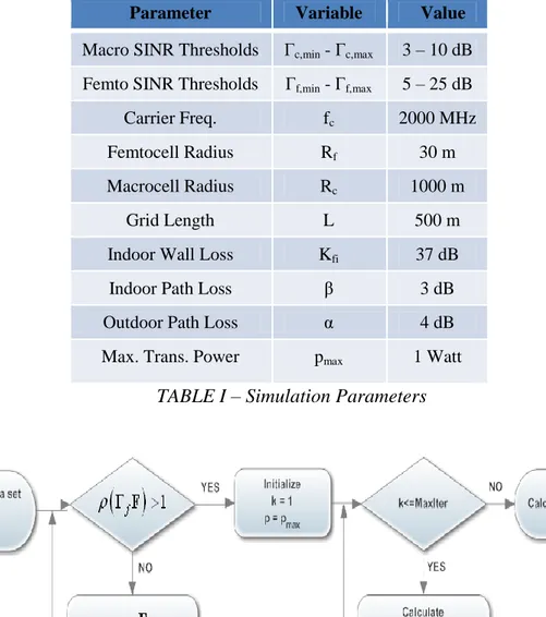
TABLE I Simulation Parameters ... 39
TABLE II Flowchart of Power Update for Femtocell User ... 39 AP PE ND IX C APPENDIX B
viii
List of Abbreviations / Symbols
2G 2nd Generation 3G 3rd Generation
3GPP 3rd Generation Partnership Project 3GPP2 3rd Generation Partnership Project 2 4G 4th Generation
AMC Adaptive Modulation and Coding AuC Authentication Centre
AWGN Additive White Gaussian Noise BSC Base Station Controller
BSS Base Station Subsystem BTS Base Transceiver Station
CATT Center for Advanced Technology in Telecommunications CDMA Code Division Multiple Access
CIR Carrier to Interference Ratio
CN Core Network
CS-MGW Circuit Switched Media Gateway
dB Decibel
DSL Digital Subscriber Line
EDGE Enhanced Data rates for GSM Evolution EIR Equipment Identity Register
eNodeB E-UTRAN Node B
EPC Evolved Packet Core
ETSI European Telecommunications Standards Institute E-UTRAN Evolved UTRAN
F-BS Femtocell Base Station FDD Frequency Division Duplex
FDMA Frequency Division Multiple Access FFT Fast Fourier Transform
ix F-MS Femtocell Mobile Station
GERAN GSM EDGE Radio Access Network
GGSN Gateway GPRS Support Node
GMSC Gateway MSC
GMSC-S Gateway MSC Server
GMSK Gaussian Minimum Shift Keying GPRS General Packet Radio Service
GSM Global System for Mobile Communications
HeNB Home evolved Node B
HeNB-GW HeNB Gateway
HLR Home Location Register
HMS HNB Management System
HNB Home Node B
HNBAP HNB Application Part
HNB-GW HNB Gateway
HSCSD High Speed Circuit Switched Data HSDPA High Rate Downlink Packet Access
HSPA High Speed Packet Access
HSS Home Subscriber Server
HSUPA High Rate Uplink Packet Access
IEEE Institute of Electrical and Electronics Engineers
IFFT Inverse FFT
IMEI International Mobile Equipment Identity IMS IP Multimedia Subsystem
IMSI International Mobile Subscriber Identity IMT International Mobile Telecommunications
IP Internet Protocol
ISI Inter Symbol Interference
ITU International Telecommunication Union ITU-R ITU Radio Communication Sector
LA Location Area
LTE Long Term Evolution
LTE-A Long Term Evolution-Advanced M-BS Macrocell Base Station
APPENDIX B AP PE ND IX C AP PE ND IX C APPENDIX B
x
ME Mobile Equipment
MIMO Multiple-Input Multiple-Output
MM Mobility Management
MME Mobility Management Entity
M-MS Macrocell Mobile Station
MS Mobile Station
MSC Mobile Switching Centre
MSC-S MSC Server
NF Neighbor Friendly
NMC Network Management Centre
NSS Network Switching Subsystem
OFDM Orthogonal Frequency Division Multiplexing OFDMA Orthogonal Frequency Division Multiple Access OMC Operation and Management Centre
OMSS Operating and Management Subsystem PAPR Peak to Average Power Ratio
PGW Packet Data Network Gateway
PSK Phase Shift Keying
QAM Quadrature Amplitude Modulation QoS Quality of Service
QPSK Quadrature PSK
RAN Radio Access Network
RANAP RAN Application Part RNC Radio Network Controller
RNS Radio Network Subsystem
RRM Radio Resource Management
SAE System Architecture Evolution
SC-FDMA Single Carrier Frequency Division Multiple Access
SeGW Security Gateway
SGSN Serving GPRS Support Node
SGW Serving Gateway
SIM Subscriber Identity Module
SINR Signal to Interference plus Noise Ratio SIR Signal to Interference Ratio
xi SNR Signal to Noise Ratio
TDD Time Division Duplex
TDMA Time Division Multiple Access TD-SCDMA Time Division Synchronous CDMA
UE User Equipment
UMB Ultra Mobile Broadband
UMTS Universal Mobile Telecommunications System
USIM UMTS SIM
UTRAN UMTS Terrestrial Radio Access Network VLR Visitor Location Register
VoIP Voice over IP
WCDM Wideband Code Division Multiplexing WCDMA Wideband Code Division Multiple Access
WiMAX Worldwide Interoperability for Microwave Access
B Base Station
D Distance of M-BS and M-MS
Di,j Distance of F-MS j and F-BS i
fc Carrier Frequency
g Channel Gain
G Normalized Channel Gain Matrix
Kc Fixed Propagation Loss of M-BS
Kfi Fixed Loss of F-BS i and F-BS i
Kfo Fixed Loss of F-MS i and F-BS j
L Length of Square Edge
p Transmission Power Vector
Rc M-BS Coverage Area Radius
α Outdoor Path Loss Exponent
β Indoor Path Loss Exponent
γ Received SINR
η Normalized Noise Vector
ρ Spectral Radius
Г,Q SINR Threshold
µ Interference Price
1
1. INTRODUCTION
Humans always need to share their emotions or introduce their feelings to others with different ways. At the beginning of humanity, drawing picture on cave walls was the used way to explain their feelings or happened things to other people. From past to present, this communication manner has been changing with respect to the technology. New developments of the technology affect communication types of people. For instance, posting letter was the most popular technique to communication but after the inventing of telephone, it was replaced with telephones. People express their feelings to each other with voice calls. Nowadays, voice calls are not enough for sharing experiences for people. When they talk to each other over a telephone network, they also would like to see their gestures and facial expressions. According to these needs, technology has been shaping by scientist for satisfying people expectations.
Mobile wireless communication technology is a type of fast-growing technology according to increasing number of subscribers and demand on high data rates. At the beginning of this technology, operator could not service in good quality thresholds to subscribers. Subscribers encouraged with interfered and less secure conversations, limited capacity and data rate. On the other hand, they had to carry big mobile equipments for communicating each other and these equipments were expensive. With the development of the electronic device technology, mobile equipments have been getting smaller and cheaper. As a result of this evolution, number of subscribers increased incredibly. Existent systems could not handle quality of service thresholds and new generation wireless mobile communication techniques have been developing to cover all needs in quality of service thresholds. Cellular concept, which was introduced by AT&T Bell Laboratories, is the manner of this technology. In the cellular technology, allocated frequencies could used at different cells (is called frequency re-use) and subscribers could change their positions cell to cell (called as handoff). Operators built their architect with respect to cellular concept and they could cover subscribers living areas. The most general
2
type of the cellular coverage is macrocell. In macrocell, operator could cover wide areas. Nevertheless, wide coverage areas are not means handle lots of subscribers. In addition to this, operators have to expand their capacities because of service to further subscribers. Due to the physical limits, if and only if cellular areas dwindle down then operators have better capacity and coverage area. Microcell and picocell structures come from these manners. Microcell and picocell provide high data rates to subscribers and if an operator has lots of these small cells, their capacity, coverage and quality of service become better. Unfortunately, because of the cost and renting problems, operator could not build these small cells to every corner or building. According to these restricts, operators began to install separate antennas in an indoor building and connect them to a macro base station. This method could solve some problems in coverage but it was not enough for high data rates on mobile stations and backhaul cost deployments could be a problem for future plans of operators.
In 1990’s, Southwest Bell and Panasonic companies develop an indoor small cell structure which was a innovation for a solution to indoor coverage but consolidation of the existent system had not available at that time [8]. According to this research, scientist have been working on short ranged and low powered cellular structure which provide better coverage, high capacity and data rate. This type of cellular structure is called femtocell which is also known as home base stations. Femtocell and its deployment are hot topics in literature. With respect to [6], the European Union has started funding research on femtocells with ICT-4-248523 BeFEMTO project which focuses on the analysis and development of Long Term Evolution (LTE) and Long Term Evolution-Advanced (LTE-A) compliant femtocell technologies. On the other hand, in Institute of Electrical and Electronics Engineers (IEEE) databases, number of published paper about femtocell topics have been increasing year by year [6]. In addition to that, some worldwide foundations like Femto Forum Limited (founded in 2007), European Telecommunications Standards Institute (ETSI) and 3rd Generation Partnership Project (3GPP) have been working on standardization of femtocells.
According to increased number of subscribers and developing technologies on smart phones, demand on data rate is increasing year by year. The goals of femtocells are provide high data rates to a limited number of subscribers with decreasing the distance between mobile stations and base stations and shrink the coverage areas of base stations for increasing available spectrum to limited number
3
of subscribers. This short ranged access points could connect to backhaul with broadband connection like cable modem, Digital Subscriber Line (DSL) or radio frequency channels [1]. In the literature, there are two types of femtocell deployments [2]. The first one is “3G Femtocells” which is called as “Home Node Bs” by 3GPP and use wideband code division multiple access (WCDMA). The second one is “4G Femtocells” also called as “Home evolved Node Bs” and it uses orthogonal frequency division multiple access (OFDMA) and single carrier frequency division multiple access (SC-FDMA) technology at downlink and uplink, respectively.
Besides femtocell deployment has some advantages, it also has some disadvantages. One of the main advantages of femtocells is auto-configuration but that advantage becomes a disadvantage for operators in some situations. Femtocell access points are not planned by operators so that, operators could not estimate the number of femtocell in their coverage area and it becomes a threat to their macrocell base stations about interference problem because of the spectrum scarcity. Chandrasekhar et al. [1] investigated technical challenges of femtocell and femtocell networks with 8 different questions. Questions are related with adaptation of femtocells on an existent network, spectrum allocation, timing and synchronization, quality of service requirements, interference managements, access methods, handoff and emergency services. With respect to these subjects, questions were answered with different suggestions. This paper also mentioned open research areas of femtocell networks as a survey and it became a major reference for femtocell researches. According to scarcity of spectrum, femtocells and macrocells have to share the same spectrum and the main technical challenge of femtocell is usage of that restricted spectrum [1]. Each operator has to manage their networks for mitigating interference. Further, operators have to take in the consideration the access modes of the active femtocells. Three different femtocell access modes in Universal Mobile Telecommunications System (UMTS) and LTE femtocells which are closed, open and hybrid, investigated at [7]. In closed access mode, only authenticated subscribers could use the femtocell spectrum, contrary to this, all subscribers could use the femtocell access point in open access mode. Not only authenticated subscribers but also other subscribers could use the femtocell access point in hybrid mode. In spite of all subscribers could use them, authenticated users have priority to utilize on hybrid mode femto access points. In 3GPP technical report
4
[5] and Femto Forum published paper [3] for a solution of these models and assumptions in UMTS femtocell networks.
In [2], authors proposed different interference and resource management approaches for OFDMA femtocells. Co-tier interference which occurs between femtocell to neighbor femtocells and cross-tier interference which occurs at different tiers of the network like femtocell to macrocell or macrocell to femtocell are supposed in different interference scenarios for both downlink and uplink. According to these assumptions, several interference management approaches as femto-aware spectrum arrangement [16] which macrocell base stations (M-BSs) develops an interference pool and this pool includes macrocell mobile stations (M-MSs) that take a role of threat to nearby femtocell base stations (F-BSs) and assigned these M-MSs to dedicated spectrum, clustering method [17], beam subset selection, collaborative frequency scheduling, fractional frequency reuse and resource partitioning [18], cognitive radio based distributed spectrum sensing and power control schemes presented in the recent literature and compared on some criteria like access mode, complexity, efficiency, transmission mode, cooperation and type of interference [2, TABLE I]. In addition, strict interference may cause deadzones at coverage area. Deadzones are created because of asymmetric level of transmission power and in the literature there are some researches for reduce deadzone and improve quality of service. In [9, 12, 14, 19-32], power allocation schemes investigated for mitigate interference on uplink or downlink and one-tier or two-tier femtocell networks with respect to signal to interference plus noise ratio (SINR), signal to interference ratio (SIR) and carrier to interference ratio (CIR). Chandrasekhar et al. [9], proposed power control algorithm in multi-tier femtocell networks with a SINR threshold. In this paper, F-BSs have to arrange their powers obtaining SINR threshold value and utility based SINR adaptation function was used for this allocation. They also investigated near-far effects of co-channels in two-tier networks and cellular link quality. In [10], power control algorithm works for mitigate cross-tier interference in OFDMA femtocell networks when limited channel state information of neighbor M-MSs are available. F-BSs could arrange their powers which was called neighbor-friendly (NF) scheme at paper, with respect to expected values of M-MSs channels information and wall loss of the F-BS coverage area. They evaluated the effects of estimation errors on the wall loss and gain of femtocell and macrocell users. In [26], M. Xiao et al. investigated utility based
5
power control with non-cooperative game for maximizing net utility. At this work, utility and cost functions was selected as sigmoid and linear, respectively and reformulate the Foschini-Miljanic [19] power control algorithm. Furthermore, they studied on adaptive and fair price settings and utility function parameters which are steepness and center. Uplink power control for CDMA systems was studied as a non-cooperative game by T. Alpcan et al. at [27]. In this paper, number of active user at network is related to minimum SIR threshold and spreading gain of CDMA system and active users update their power with parallel or random update algorithms on centralized or decentralized pricing schemes. In [31], non-cooperative game for power control in CDMA systems is extended to multi-carrier CDMA case. X. King et al. studied on price-based power allocation on femtocell networks with Stackelberg game approach at [33]. Upper and lower bounds of utility based power allocation scheme has founded for urban areas and closed form formulation has obtained for rural areas. On the other hand, uniform and non-uniform pricing scheme has studied with respect to dense of access points. Moreover, in the literature there are some studies on scheduling and power allocation for uplink SC-FDMA systems [34, 35]. In [34], SC-FDMA is investigated in two different subcarrier mapping scheme which are Localized-FDMA (L-FDMA) and Interleaved-FDMA (I-FDMA). In addition, set of subcarriers called as chunk in the paper, assigned to different users and minimum mean square error (MMSE) frequency domain equalizer used for preventing the inter symbol interference (ISI). After these considerations, power and bit allocation for multiple set of subcarriers with respect to capacity of users are investigated.
In this thesis, motivated by mitigating the cross-tier and co-tier interference where power allocation schemes are used in femtocell networks, we generalize the work in [9] and [33]. Different from the [9] and [33], the contribution of the current study is to investigate the effects of the number of active users and distance between macrocell base station to femtocell base stations square grid for randomly activated femtocell base stations in a known region with adaptation of game theoretic power algorithm with respect to given SINR thresholds for single antenna systems. Firstly, we generalize the SINR for FDMA system then, use it for maximizing the utility function of each femtocell users for adaptive power allocation and mitigation of interference on network with using proposed utility function in [9]. Secondly, optimal solution of interference prices and femtocell users power are founded with
6
respect to utility function of the macrocell base station under a known interference constraint for de-centralized and centralized sensing schemes. After that, we adapt the given solution to CDMA systems and observe the effects of number of active users and their SINR values.
The rest of the thesis organized as follows. In Chapter 2, general introduction to cellular communications and their evolution are presented. Femtocell solution to increasing demand on high data rates and different types of femtocell deployments are introduced in Chapter 3. Furthermore, system model and power control are described at Chapter 3. In Chapter 4, the performance gains of proposed scheme are evaluated by simulations. Chapter 5 concludes our work and gives some ideas for future researches.
7
2. GENERAL INTRODUCTION TO CELLULAR
COMMUNICATIONS
Wireless communication systems were used for special-purpose communication years ago whereas it effects directly to all human life today. Wireless systems contain enhanced standards, technologies and communication techniques to satisfy the need of users at various application areas. Served systems are generally classified as service type, data rate, throughput, performance and reliability.
The most popular application of wireless communication systems is cellular systems. Subscriber and bandwidth need rises day to day by means of developing technology. Cellular phone systems proposed for transmit voice signals at first whereas it replaces with advanced mobile communication systems for access to internet in the recent times.
Smart phones and tablets provide easy access to social media, file transfers, e-mail services and internet surfing. Because of these services, people use their mobile stations to reach and share the data. Also, recently developed applications which are video talk, mobile television, real time video conference and location based service and wideband mobile communication technologies triggered number of subscribers to increase. With respect to these improvements, new generation mobile communication systems’ traffic will replace by multimedia data transfer. It can be foreseen that new generation systems will need wideband technologies but because of the spectrum scarcity, operators could not allocate wide bandwidth to supply these multimedia services. Therefore, it is significant that new developing techniques should use current frequency spectrum efficiently.
2.1. 2nd Generation (GSM) Systems
At the beginning of 1990’s, first generation system could not supply good quality to their subscribers due to the fact that the number of subscribers had been
8
increased dramatically. Telecommunication companies and scientists wanted to improve the used system and service to all subscribers in a specific quality of service thresholds. At 1991, Global System for Mobile Communications (GSM) introduced the first standardization on second generation (2G) systems in Finland. In this system, communication over channel has been using digital processes. With the digital systems, subscribers have high quality and capacity for communication. In 2G systems which work on 900, 1800 and 1900MHz, Time-Division Multiple Access (TDMA) and Frequency-Division Multiple Access (FDMA) techniques are used for channel access. FDMA has 25MHz bandwidth and 124 carrier frequency (bandwidth divided into 200 KHz parts). These carriers separated on time axis by TDMA [37, 38].
2G systems which have low data transfer rate are developed as a result of multimedia services interest and toward the quick rise of data transfer. Despite reaching 64 Kbps data transfer rate with these 2G systems, HSCSD (High Speed Circuit Switched Data) system is developed which has not common usage. Due to have immediate rise of data transfer for short periods and have generally stable channel traffic for long periods, network resources are not used in the mobile systems. For that reason, data packages are generated so as to manage data traffic more efficient. Hence, 2.5G systems have been started to use with the help of packet switching technique since ending of the 1990s.
GMSK (Gaussian Minimum Shift Keying) modulation and 140 Kbps data rate characteristics belong to general packet radio service (GPRS) and on the other side 8PSK (Phase Shift Keying) modulation and 384 Kbps data rate characteristics belong to enhanced data rate for GSM evolution (EDGE).
Adaptive modulation and coding technique (AMC) is utilized for EDGE consistent mobile phones. Hence depending on measured signal noise ratio (SNR) feedback value, the best modulation type is determined. Put it simply, 8PSK modulation is used for data transmission whereas GMSK modulation is used for noisy channel conditions [37].
GPRS and EDGE systems aim to low latency owing to be formed by 2G systems developments. Due to increased usage of multimedia services, new generation mobile communication systems focus on to provide high capacity and high data rates.
9 2.1.1. Network Architecture
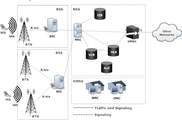
GSM network architecture includes three sub-systems which are base station subsystem (BSS), network switching subsystem (NSS) and operating and management subsystem (OMSS). BSS operates radio communication processes and signaling process from mobile station to NSS. Call processing and subscriber related transactions are carrier out at NSS. OMSS is responsible for monitoring the alarm system and occurred traffic at network. The network architecture of the GSM system is shown in Fig. 2.1.
Figure 2.1 GSM Network Architecture
Mobile Station (MS) consist of mobile equipment which is called as smart phone today and identified with international mobile equipment identity (IMEI), and subscriber identity module (SIM) card which stores information about the subscriber like keys for authentication and international mobile subscriber identity (IMSI). A MS could join to the network with Um interfaces which also called air interface and
include 200 KHz channels.
Base Transceiver Station (BTS) is also called base stations, consist of radio transmitter and receivers, radio transmission equipments, antennas and amplifiers and it provide service to MSs at cells. BTS controls the Um interface which is the
10
connected to only one BTS. BTSs connected to base station controller (BSC) with Abis interface which is include 16 or 64 kbit/s connections.
Base Station Controller (BSC) manages one or more than one BTSs. It gathers the measurements of MS and BTS and handles power control, channel allocation and decides to handover or handoff processes. It connected to mobile switching center (MSC) with A interfaces. A interface carries the information of timeslots and enable channels.
Mobile Switching Center (MSC) is a unit of call switching processes. It manages several BSCs in an area and controls incoming and outgoing calls to MS and originates inter-MSC handovers, call setup, call termination and call forwarding. It has also connections between NSS’s units for switching and provides some services like authentication, registrations. The connection between Gateway MSC (GMSC) provide a link for communicate other networks.
Home location register (HLR) is a database which stores administrative information about each subscriber. Location area (LA), roaming information, IMSI number, connected MSC and visitor location register (VLR) of the mobile station is stored at HLR. When a MS change its LA, it informs MSC for handover process and MSC updates its current location area at HLR database. It includes big amount of subscribers in an operator and answer real-time request within short time. These data stored at HLR until subscription cancellation of a subscriber.
Visitor Location Register (VLR) is a dynamic database and stores temporary information of mobile stations. It is associated with a MSC service area and stores LA information of current MS in that area. It keeps HLR data temporarily. The structure of the HLR and VLR prevent frequent HLR updates.
Equipment Identity Register (EIR) is another database at NSS and it stores IMEI numbers of mobile stations. It decides a mobile equipment have a permit to connect network. This decision is taken by EIR with respect to IMEI number.
Authentication Centre (AuC) keeps safe the user identity and information transfer. SIM card of each subscriber has key information which is called authentication key and links could be protected with using these keys at mobile station and authentication centre. At authentication centre, special algorithms work for decryption of the protected data.
Network Management Centre (NMC) and Operation and Management Centre (OMC) are the units of the OMSS. NMC controls the subordinated OMCs. OMC
11
monitors network and reports situation of network and their traffic. Number of OMC in a network is changed with respect to size of the network.
2.2. 3rd Generation (UMTS) Systems
In 1990s, ITU (International Telecommunication Union) had been starting to work on defining standards (IMT 2000 – International Mobile Telecommunications 2000) which will be used in third generation (3G). Two different working teams which are 3GPP and 3GPP2 performed studies to remove different and inconsonant standards for 2G systems and it is aimed that universal mobile communication system to be developed [39].
3GPP team worked to develop GSM standard whereas 3GPP2 team aimed to develop cdmaOne standard. As a result of conflicts between the two groups, different standards for 3G are come up. Consequently, three different standards which are W-CDMA (Wideband CDMA) developed by 3GPP, CDMA2000 developed by 3GPP2 and TD-SCDMA (Time Division Synchronous CDMA) developed by CATT (Center for Advanced Technology in Telecommunications) can be analyzed. The most common W-CDMA standard has 5 MHz bandwidth and data rate is estimated 144 Kbps for mobile users, 384 Kbps for urban usage and 2 Mbps for constant usage.
3G systems support not only IP (internet protocol) but also non-IP data traffic. 2003 onwards, initial commercial 3G systems can be seen firstly in England and Italy in Europe. UMTS technology is the most preferred one within the 3G systems and it constitutes to develop mobile systems soon after GSM and EDGE. UMTS technical features were completed by 3GPP team and numerous partners in 1998. UMTS technology presents higher data rate and spectral efficiency than TDMA and FDMA which are used in 2G systems. Lastly, UMTS technology provides opportunity for benefit from multimedia services with the support of asymmetric data rate.
Mobile service usage has been becoming widespread in 3G systems and as a result the need of high capacity and data rate is raised. Accordingly, with version 5 HSDPA (High Rate Downlink Packet Access) and with version 6 HSUPA (High Rate Uplink Packet Access) is developed by 3GPP. Maximum data rate was increased to 14.4 Mbps for download with HSDPA technology in 2005. On the other
12
hand, high transfer rate is also needed for uplink. In accordance with this need, data rate was raised to 5.76 Mbps with HSUPA technology in 2007.
HSDPA and HSUPA technologies are called HSPA (High Speed Packet Access) which is very significant to UMTS technology development. Moreover, HSPA technology is assessed as 3.5G and developed by 3GPP. Also, 16QAM modulation is used for downlink whereas QPSK modulation is used for uplink. 3GPP version 7 provided additional features for HSPA as 64QAM and MIMO (Multiple-Input Multiple-Output) and thus HSPA+ technology was developed. As a result, data transfer rate was increased to 42Mbps by HSPA+.
Next step was version 8 which was developed by 3GPP and it was called LTE technology. This technology increased data rate to 100 Mbps for downlink using OFDM (Orthogonal Frequency Division Multiplexing) technique and to 50 Mbps for uplink using SC-FDMA (Single-Carrier FDMA). Obtained data rates are nearly 3 times as much than HDSPA and HSUPA. Additional MIMO support provides up to 326 Mbps data rate. It will be possible to use new services like IPTV, VoIP, high resolution video etc. along with becoming widespread of UMTS based technologies.
2.2.1. WCDMA
W-CDMA standard has 5 MHz bandwidth, 3.84 Mcps chip rate and data rate is estimated 2 Mbps for mobile users. In addition to that it is able to carry over 100 simultaneous calls. According to latest releases data rate have been increased to 14.4 Mbps. The difference between CDMA and WCDMA, information is spread over a wide band and this information multiplying with chips from spreading codes of CDMA in WCDMA. In CDMA, orthogonal code sequences or pseudo-noise sequences generates waveforms and these generated waveforms are modulated with user data. At the result of this process, original information is spreading over the available frequency. WCDMA allow frequency division duplex (FDD) and time division duplex (TDD). Separated different 5 MHz carrier frequencies are used for both downlink and uplink in FDD but only one radio channel could be used at uplink and downlink at different times.
13
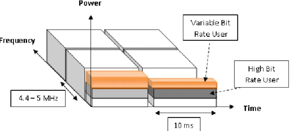
Figure 2.2 WCDMA Bandwidth Allocation
In Fig.2.2, bandwidth allocation of WCDMA with respect to time and frequency bands is shown. 4.4-5 MHz bands are allocated for users and these bands also separated with respect to time and spreading codes. According to reuse capability of frequencies with different codes, WCDMA provides high spectral efficiency. In addition to that, many users could access same frequency band with using different spreading codes. This means, capacity of the UMTS networks is greater than the GSM network. On the other hand, in [39] mentioned that wideband signal has better performance than the lower bandwidth signal at different propagation paths and UMTS systems have higher diversity content against fading.
WCDMA designed to be co-operated with existent GSM network. GPRS and EDGE technologies also could be used in UMTS networks. With this approach, UMTS systems could be installed at existent 2G base station with only using different antennas and external TRX equipments.
2.2.2. Radio Access Network Architecture
UMTS network could be divided into 3 groups which are user equipment, UMTS terrestrial radio access network (UTRAN) and core network (CN). UTRAN originates radio based processes and provides connection between core network and users. Data transfers and switching calls at internal or external networks carried out by CN.
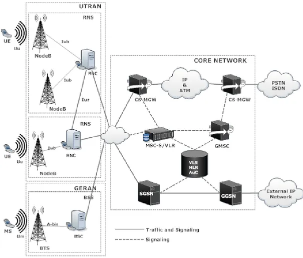
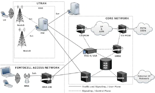
GSM EDGE radio access network (GERAN) is used for GSM subscriber connection to network. Release 4 network architecture which is proposed by 3GPP is shown in Fig.2.3. In Release 4, circuit switching and control units are separated at
14
core network. Accordingly, increase data transfer throughput and easy transition to IP-based networks are aimed. MSC is divided into MSC-Server (MSC-S) and circuit switched media gateway (CS-MGW) units for providing this structure.
User equipment (UE) is the same with the mobile station in GSM. It is consistent with 3G interfaces. As in the case with GSM, UE is consisted of mobile equipment (ME) and UMTS subscriber identity module (USIM). BTS at the GSM system is called Node B in UMTS systems. The base station of UTRAN system Node B connected to UE with Uu interfaces and connected to radio network
controller (RNC) with Iub interfaces. Node B gives information to RNC about the
link quality with Uu interface. It originates incoming and outgoing calls to UE.
Figure 2.3 UMTS Network Architecture
Radio Network Controller (RNC) controls Node Bs which are connected to one RNC. Iur interface connects different RNCs and RNCs connected to core
network with Iu interface. RNC and connected Node Bs to these RNCs compose
15
MSC-S is responsible for controlling incoming and outgoing calls and roaming subscriber management. It works with MGW and it controls more than one CS-MGW. In its structure, there has a VLR database. CS-MGW monitors circuit switched incoming and outgoing traffic and process it. It is connected to UTRAN with Iu interfaces and connected to GERAN with A interfaces. On the other hand,
CS-MGW connected with external networks and provides a conversion of circuit to packet switching carrier techniques. Accordingly, data carried on time slots converted to IP packets or vice versa.
Gateway MSC-S (GMSC-S) provides a connection with external networks. Serving GPRS support node (SGSN) controls internal packet switching traffic and have some functions like mobility management, session management, interaction with other areas of the network and billing. Gateway GPRS support node (GGSN) controls external packet switching traffic.
Other elements of the architecture which AuC, VLR, HLR and EIR shared with GSM network architecture.
2.3. 4th Generation (LTE) Systems
The major requirement for systems beyond 3G is higher data transfer rate and communication capacity. In 2008, some standards which fulfill these requirements were defined by ITU-R (ITU – Radio communication Sector) and fourth-generation (4G) communication systems development was planned. 4G term includes not only cellular systems but also wide band wireless access systems as WiMAX (Worldwide Interoperability for Microwave Access).
4G systems represent not only higher data rate and communication capacity but also more mobility, service quality (QoS), security and lower latency. It will be provided to benefit from new generation mobile services as ultra wide band internet access, multimedia content entertainment via internet, high quality audio and high resolution video associated with 4G systems.
3GPP planned to use LTE-A technology which has MIMO support property, high rate data transfer, coordination between base stations and heterogeneous network usage. LTE-A technology is defined as 3GPP version 10 and development studies are started in 2008 March. Commercial use is expected to use in 2013 and
16
2015. Moreover, it is estimated that LTE-A data transfer rate will reach to 1.6 Gbps in 2015.
802.16m standardization finished in September 2009 which was developed by IEEE. According to the announced rating system results of ITU-R in October 2010, both LTE-A and 802.16m technologies meet all the required condition successfully for IMT-Advanced. There are minimal differences between LTE-A and IEEE 802.16m standards like LTE-A uses for downlink and uplink OFDMA and SC-FDMA respectively and on the other hand IEEE 802.16m uses for downlink and uplink only OFDMA.
Another 4G technology is UMB (Ultra Mobile Broadband) which is developed by 3GPP2 team. UMB technology is defined with regard to 3GPP LTE in order to solve compatibility problem. Furthermore, OFDM technique is used instead of CDMA for UMB technology. 288 Mbps and 75 Mbps data rate is enable for downlink and uplink respectively, owing to 20 MHz bandwidth.
2.3.1. OFDMA
4th generation system prefer OFDM modulation at their downlink because OFDM provide spectrum efficiency, high data rate transmission and robustness to multipath fading. In addition to that, according to orthogonality property and used techniques cyclic prefix and guard interval, it prevents inter symbol interference (ISI).
OFDM is the special case of multi carrier modulation which is the principle of transmitting data by dividing the stream into several parallel bit streams and modulating each of these data stream onto individual carriers or subcarriers. Large number of subcarriers modulated with low data rate and transmitted over parallel channels. These narrow band channels could be reached high data rate streams. 15 KHz subcarrier spacing used and this reciprocal to data rate in OFDM. LTE systems has very low rate (15 Kbps) if you compare the UMTS systems (3.84 Mbps) but in LTE these low rate subcarrier spaces use at 5 MHz bandwidth and it reaches 4.5 Mbps data rate [40]. In OFDM, subcarrier frequencies are chosen orthogonal to each other. This means, during the sampling of one subcarrier, the other subcarriers have zero value and other subcarriers could not affect the sampled subcarrier information.
17
In OFDM system, input data is in frequency domain. This data series connected in serial to parallel converter and connected it to multicarrier modulator which is the inverse fast Fourier transform (IFFT) and converts frequency domain signal to time domain signals. Cyclic prefix adding at transmitter part of the system and deleting the receiver part of the system. Cyclic prefix added data connected to parallel to serial converter. Then, digital signal is converted to analog signal for transmitting. At the receiver part, the analog signal is converted to digital signal and connected serial to parallel converter. After that it connected to multicarrier demodulator (FFT). This demodulated symbols connected to detector and then converted with parallel to serial converter.
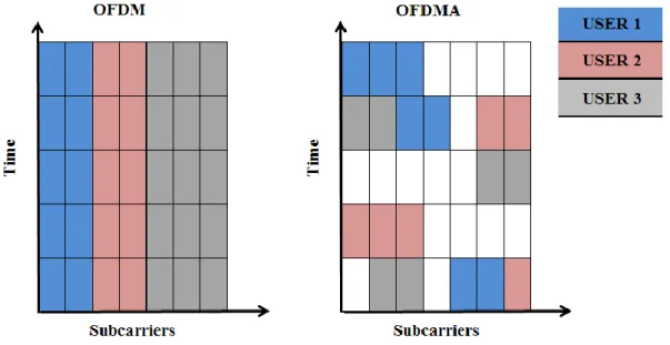
OFDMA is a variant of OFDM modulation which provides multi user transmission. In OFDMA, different time slots on a subcarrier could be allocated different users.
Figure 2.4 Subcarrier allocation of OFDM and OFDMA
Fig 2.4 shows the differences between OFDM and OFDMA technologies. Subcarriers allocated dynamically among the different users of channel with respect to time slots in OFDMA. Scheduling users by frequency and time slots, narrow band interference and multipath fading are prevented. Accordingly, OFDMA systems are robust and have increased capacity [40].
18 2.3.2. SC-FDMA
SC-FDMA is a form of OFDM modulation and used in LTE system at uplink. The one of the drawbacks of OFDM is high peak to average power ratio (PAPR). Due to the high PAPR, mobile stations are not convenient for using OFDM at uplink transmission because they have to amplify this high power. Unfortunately, battery of mobile stations could not operate this process. Accordingly, SC-FDMA used for transmission from mobile station to base station. It combines low PAPR techniques of single carrier transmission systems with robustness to multipath and flexible frequency allocation of OFDMA [40]. On the other hand OFDMA and SC-FDMA allocation of time slots and subcarriers shown in Fig.2.5. [40, Figure 2.3-1]. According to figure, although each 15 KHz frequency bands allocated different users at same time slot in OFDMA, different time slots assigned different users with whole frequency subcarriers without high PAPR.
Figure 2.5 OFDMA and SC-FDMA frequency and time allocations
2.3.3. System Architecture Evolution
Increasing number of the network elements lead to increase burden of the backbone. New base stations are installed by operators for supplying adequate conditions to subscribers like capacity, coverage and data rate. On the other hand,
19
operators have to monitor their network and manage them for improving service quality. Accordingly, core networks elements should be consist of intelligent devices. A core network with intelligent devices provides robustness and easy managing to a network. The evolution of the network architecture is started with respect to these situations. The evolved systems should provide optimized packet switched services, high throughput and data rate to end users, improved accurate and decreased latency packet transmission [41]. Furthermore, evolution of system architecture should not defuse the existent systems, it should co-operated with existent systems and also sufficient to development of the architecture.
3GPP has huge impact on the evolution of the system architecture. Purposes of this evolution are decreases network components, getting intelligent them and use flat IP to transport all services. In Release 6, GGSN, SGSN, RNC and Node B are connected with data and signaling transmission. At Release 7, RNC combined with Node B and it has a direct connection to GGSN user plane which is also called data and connected to GGSN over SGSN for control plane which is called as signaling. Release 8, which is the first LTE release, system architecture evolution (SAE) had started. SAE provides many advantages to operators. These advantages are capacity improvement, packet switched data transfer over all IP network, high response with reduced latency and reduced expanses for operators with decreased number of network components. Co-operation between WiMAX and LTE/UMTS technologies are announced with Release 9. It also provides MIMO technologies. With Release 10, LTE Advanced was finalized and in Release 11, third party application has a co-operation with LTE-A. Nowadays, 3GPP is still working on Release 12 which content is still open now.
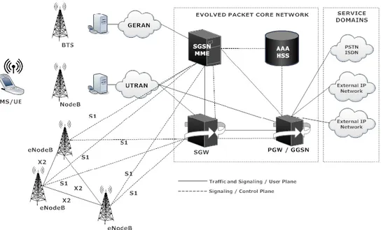
System Architecture Evolution has four main components which are user equipment (UE), evolved UTRAN (E-UTRAN), evolved packet core (EPC) network and service domains. The evolution has been continuing on E-UTRAN and EPC units. Network deployment of SAE is shown in Fig.2.6.
UE is typically handset such as used in 2G and 3G networks and provide communication links with network. LTE based UEs also provide voice calls over IP which called as VoIP with using some applications.
E-UTRAN node B (eNodeB) is a base station which controls all radio related functions of the network. It is responsible for radio resource management (RRM), mobility management (MM), ciphering/deciphering, IP header
20
compression/decompression, bearer handling, data delivering and UE radio signal level measurements control. It is connected to serving gateway (SGW) of the EPC with “S1” interfaces and connected to other eNodeBs with “X2” interfaces. The eNodeB structure provides fast routing for incoming and outgoing calls with less interaction with EPC.
Figure 2.6 Evolved Network Architecture
Evolved packet core network consist of four main units which are mobility management entity (MME), serving gateway (SGW), packet data network gateway (PGW) and home subscriber server (HSS).
MME handles signaling and controlling of UE for management of network connection, assignment of network resources, authentication, security, roaming, paging and handover. It is the main control unit of the EPC and has connections with SGW for controlling tunnels, with eNodeBs for paging, mobility management and handover processes, with HSS for user profile, authentication and security parameters and location management, with other MMEs for idle state mobility and handover between MMEs.
SGW is data plane unit in EPC and act as a demarcation between RAN and core networks [42]. SGW is a relay between eNodeBs and PGWs. It transports all IP data traffic between UE and network and routes incoming and outgoing data packets.
PGW is a termination point between EPC and service domains like Internet, IP Multimedia Subsystem (IMS) and IP domain server. It provides IP address
21
allocation to UE for communicating external networks and controls policy and charging.
HSS is a database which contains all subscriber related information. On the other hand, AuC is a part of the HSS. Subscriber related information includes enable services, allowed packet data networks and visited networks [41]. It has a connection with MME for location management and authentication processes.
22
3. HOME BASE STATIONS: FEMTOCELLS
In this chapter, initially way to femtocell technology and benefits of this technology will be introduced. Secondly, 3G and LTE femtocells network architecture will be presented. Then, one of the important interference management techniques which power control algorithm will be explained with our system model.
3.1. Way to Femtocell Technology
Due to the increasing demand on capacity and data rate, service providers have to get their cells smaller to service all subscribers in adequate conditions. According to observation of Martin Cooper who is inventor of the mobile phone, since Guglielmo Marconi’s first radio transmission, voice or data transmission over a given physical region has doubled every 30 months. This observation also called as “Law of Spectral Efficiency”. On the other hand, developed smart phone applications leads to need on high data rates at user’s personal areas like home and office. In [43], usage of mobile phones for voice calls (more than %50) and data traffic (more than %70) occurs at indoors.
2G systems can handle voice calls but have not enough capacity and coverage for high data rates. On the other hand, 3G systems provide high data rates to mobile users but nowadays this amount of provided data rates are not sufficient to users. Furthermore, indoor signal strength weak for high data rate transmission. Operators have to build new macro base stations to increase the data rate and capacity. The goal of building new base stations is to decrease the distance between base stations and mobile users and service to users with strong signal power. This means that transmit and receive antenna distance should be small for high capacity and data rates. Unfortunately, this solution approach is not feasible for operators because of cost and burden of network. In this regard, mobile operators developed a device
23
which can be installed by users at the interior of house, office, etc. and can communicate with the mobile network over a DSL connection, radio-frequency backhaul or cable modem. This device is called femtocells or home base stations. The mean of “femto” prefix is 10 to the power -15 or quadrillionth. Just because of this, these devices called as home base stations.
Femtocells are inexpensive, short ranged and low powered base stations. It improves network coverage and provides high data rates to indoor mobile users. Further, it improves indoor signal strength and allocate wide spectrum to few number of subscribers. The serving number of subscribers changes with respect to vendor’s design.
Femtocells have lots of benefits to subscribers and operators. The most important benefit for both operators and subscribers is low cost. Operators enlarge their coverage area without any new site or tower installation with femtocells. On the other hand, subscribers have adequate conditions and high data rates with low prices because femtocells connected to backhaul via internet. Also broadband connection to core network reduced burden of the backbone of operators. In addition to that, power consumption has positive feedback to expanses of operators. Femto access points could be setting from subscribers and its electric consume funded by subscribers.
The second important advantage of femtocells is higher spectral efficiency and data rate. Femtocells provide qualified service to customers because of high spectral efficiency. It allocates wide spectrum to a set of subscribers. Furthermore, with respect to the short transmit and receive distance, mobile handset has long battery life. Additionally, this reduced transmit and receive distance leads higher signal to interference plus noise ratio levels. Femtocell base station transmits with low power and interference threat to other femtocells or macrocell users could be less. Due to both these causes, femtocell improves capacity.
Femtocell access points are self-adapted units. Operator installation or configuration need not for home users. Plug-and-play property of the femtocells provides easy installation to home users and it leads to easy deployment on marketing of femtocells.
Femtocells have been developing technology by 3GPP, Femto Forum and ETSI. In 3GPP terminology, 3G femtocells called as Home Node B (HNB) and LTE femtocells called Home evolved Node B (HeNB). HNBs are specified with 3GPP
24
Release 8 and it uses WCDMA technology for increase capacity and provides high data rates to indoor users [5]. According to this release, outline of HNBs are described. It also describes network architecture, co-operation with other 3GPP technologies, access modes, interference scenarios, management schemes and requirements.
3.2. HNB and HeNB Network Architecture
According to 3GPP standards and technical reports [5, 46-48], 3G femtocell network has different elements and new interface from UTRAN network architecture. A key point in architecture design has been to ensure scalability regarding a potential large volume of connected HNBs [44]. The new elements of the HNB architecture are HNB, HNB gateway (HNB-GW), security gateway (SeGW) and HNB management system (HMS). Deployment of HNB network architecture is shown in Fig.3.1.
Figure 3.1 HNB Network Architecture
HNB is a short ranged, low powered femtocell access point and provides high spectral efficiency and data rates to a set of subscribers. These devices used by subscribers when plug in and self adapted to core network. It has a connection to HNB-GW with Iuh interfaces. Iuh is an open interface and provides link between
25
HNB and HNB-GW. Iuh also introduces two new protocols which are HNB
application part (HNBAP) and radio access network application part (RANAP) user adaptation (RUA). HNBAP handles registration and deregistration processes between HNB and HNB-GW. On the other hand, RUA handles setting up and deleting processes for RANAP Iu connections and transferring RANAP messages.
HNB-GW provides a connection to UTRAN for 3G femtocells with Iu
interfaces. A far amount of HNBs connected to core network with HNB-GW. In other words, it loaded with high data traffic. On the other hand, it provides registration of UE to HNBs and synchronization. SeGW provides secure IP addresses for Internet connection of HNBs and core network. Also it authenticates HNBs to core network. HMS provides configuration data to HNB based on TR-069 standards. It performs HNB location verification and operational parameters.
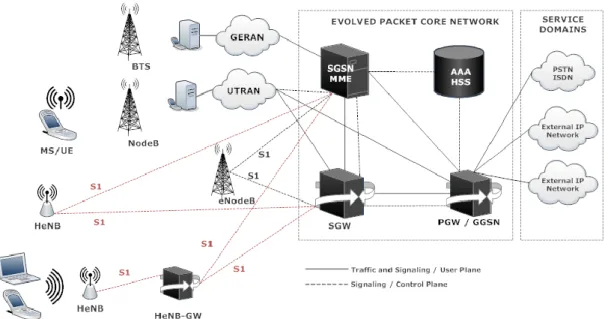
The differences between 3G and LTE femtocells network architecture are used femtocell access point, gateway and interfaces between them. In LTE femtocells network, femtocell access point called as HeNB and it connected to mobile stations with LTE Uu interface which uses OFDMA for downlink and SC-FDMA for uplink.
On the other hand, HeNB connected to HeNB gateway (HeNB–GW) with S1 interface and HeNB-GW provides connection for a far amount of HeNB to management entity and serving gateway. In addition to that, HeNB-GW provides secure IP tunnels with HeNBs. In Fig.3.2 shows HeNB network architecture.
26 3.3. Power Control in Femtocell Networks
One of the most important interference management scheme is power control. According to near-far effects of mobile station and femtocell access points and asymmetric level of transmission power, macro-to-femto, macro, femto-to-femto interferences and deadzone problems may occur. Power control algorithms are solution of these problems with controlling mobile station transmit power which means effective battery consumption at handset and minimizing interference which occurred by other users to another cell.
Occurred interferences classified in two types, co-tier interference is mentioned to interference originated at same tier like femto-to-femto. Cross-tier interference happened at different tiers of the network like macro-to-femto and vice versa. Deadzones are related with unbalanced power consumption at base station and mobile station. For instance, if a mobile station located at cell edge of the mobile station coverage area, it has to transmit data with high power levels and it may leads interference to another user or femto access points. Also, base station has to transmit high level power to reach the cell edge users and it may leads interference. Co-tier, cross-tier interferences and deadzone problems could be solved by effective power control algorithms.
In adaptive power control algorithms, mobile stations adjust their transmit powers with respect to SINR threshold parameters given by operators or distance from the macrocell base stations. On the other hand, game theoretic approaches are used for adaptive power allocations. Users arrange their transmit powers for reaching adequate conditions from base station but also they have to consider other users and base station service quality and adjusts their power for prevent unaccepted interference to others.
Macrocell base station B0 provides coverage area with radius Rc. Femtocell
base stations (F-BSs) connected to network in this coverage area over the M-BS. N number of F-BSs Bi where i=1,2,..,N active in this area. During each signaling slot,
one scheduled user active at cell and transmits with pi Watts power. The received
SINR γi of user i at Bi is equal to
, 2 , i i i i j i j j i