DOI: 10.1501/commua1-2_0000000088 ISSN 1303-6009
© 2015 Ankara University AN IMPROVED MMSE-BASED ESTIMATION ALGORITHM FOR COHERENT WIRELESS UNDERWATER OPTICAL OFDM
COMMUNICATION SYSTEM
FATİH GENÇ1, EMRE YENGEL2
1Electrical and Communication Eng., Cankaya Uni., Ankara, TURKEY
E-mail:[email protected],
2National Nanotechnology Research Center (UNAM), Bilkent Uni., Ankara, TURKEY
E-mail:[email protected]
(Received: September 03, 2015; Accepted: October 26, 2015 )
ABSTRACT
In this study, we proposed an improved Minimum Mean Square Error (MMSE) channel estimation algorithm for the coherent wireless underwater optical OFDM system aiming to improve parameters such as dispersion, attenuation and optical noise. The simulation results of the proposed algorithm was compared with the performance of Discrete Fourier Transform (DFT) based and time based Least Square (LS) and MMSE channel estimation techniques. The results demonstrated that the proposed approach improved the underwater wireless channel estimation performance and offers a promising alternative for the OFDM systems with less complexity and high efficiency.
KEYWORDS: Underwater optical communication, channel estimation, Least Square, Minimum Mean Square Error.
1. INTRODUCTION
The studies of the underwater wireless communication in the past few decade mainly focused on acoustic communication. However, studies on the underwater wireless optical communication is rising recently due to the limitations of the existing acoustic systems such as lack of providing high data rates and suffering from latency. By providing high data rates in the range of 1Mbps to 1Gbps and low-latency, optical wireless communication is a promising alternative for the underwater applications [1-3]. Although having such advantages, analyzing optical wireless communication systems in underwater environment is a challenging task owing to the nature of water. The optical properties of seawater can be considered in two main groups called as inherent and apparent. Absorption process and single scattering in seawater are related with the inherent optical properties
26
whereas illumination geometry, transmission and reflection processes caused by the sea surface and sea bottom are related with the apparent optical properties [4,5].
As the light propagates in the underwater medium, it is being affected mainly by absorption and scattering which are two main causes of the attenuation. Absorption process is originated from various materials in the water such as inorganic materials, dissolved salts and organic substances like chlorophyll and colored dissolved organic matters. Because absorption and scattering is wavelength dependent, propagation of light in underwater is also dependent to wavelength [6,7]. Moreover, stretching of the signal pulses due to scattering causes the inter-symbol interferences (ISI) in communication links [8,9] making the channel unreliable when transmitting the data with high rates or over long distances.
Since introducing the described parameters for the underwater optical channel (UWOC) is a challenging task, in the literature exponential attenuation model was used for the channel modeling while neglecting the time dispersion [10,11]. Different from those studies, we considered the channel with time dispersion in this work [12]. In the previous studies, effects of the various modulation techniques such as on-off-keying (OOK), pulse-position modulation (PPM) or Optical Orthogonal Frequency Division Multiplexing (OOFDM) on the performance of the UWOC were investigated. [13,14]. Among them, OFDM based systems are convenient to channel estimation and compensation capabilities. As one of the drawbacks of the OOFDM systems, increases in the transmission rates cause some impairments such as optical noise, time dispersion and non-linearity. Therefore, channel estimation becomes an important factor on the accuracy of the transmission link. Previously, researchers have studied Least Square (LS) estimation and improved LS estimation for these systems [14,15]. In these studies, it is showed that improved LS channel estimation is suitable for OOFDM and high order modulation techniques. In this work, we propose an improved MMSE channel estimation algorithm for OOFDM system in the UWOC channel. For this purpose, after defining an improved OOFDM system for UWOC system, the performance improvement of the systems with the proposed channel estimation method under some impairments such as time dispersion and optical noise is shown with the simulation results. The performance of the proposed method is also compared with the methods studied in the literature.
UNDERWATER OPTICAL OFDM COMMUNICATION SYSTEM
The paper is organized as follows; Section II gives an overview of the underwater wireless optical channel model, Section III overviews OFDM system structure, in Section IV, MMSE DFT-based channel estimation methods are defined in detail, numerical results and discussions are given in Section V and finally, conclusions are drawn out from the results in Section VI.
2. WIRELESS UNDERWATER OPTICAL CHANNEL MODEL
The aquatic environment comprises different elements, dissolved or suspended in pure water with different concentrations as well as plants, phytoplanktons, zoo planktons, marine species and plants [13] which are produced by plants. Among these materials, optical properties of the oceanic water is mainly determined by the density of particles called phyto planktons [14]. These matters cause redirecting the transmitting light or converting it into the different form like heat according to the two fundamental physical process which are called scattering and absorption. In this study, Haltrin’s model is preferred for the analysis where the attenuation coefficient c(λ) of the medium is calculated by the addition of the absorption and scattering coefficients, a(λ) and b(λ) is shown respectively.
( ) ( ) ( )
cλ =aλ +bλ (2.1) where λ is the wavelength of light. In view of this assumption, the absorption coefficient is defined as [14]
( ) ( )
0 0 0 0
( ) ( ) ( )( )0.602 kf kh
w c c c f f h h
a λ =a λ +a λ C C +a C− λ +a C− λ (2.2) The details of the parameters are given in Table 1. The concentrations 𝐶𝐶𝑓𝑓 and 𝐶𝐶ℎ are expressed through the chlorophyll concentration 𝐶𝐶𝑐𝑐 as below [14]: 0 1.74098 exp[0.12327( )] f c c c C = C C C (2.3) 0 0.19334 exp[0.12343( )] h c c c C = C C C (2.4) On the other hand, the scattering coefficient 𝑏𝑏(𝜆𝜆)is expressed as;
28
0 0
( ) w( ) s ( ) s l ( ) l
bλ =b λ +b λ C +b λ C (2.5) where 𝑏𝑏𝑤𝑤(𝜆𝜆)is the scattering coefficient of the pure sea water and 𝑏𝑏𝑠𝑠0(𝜆𝜆) and 𝑏𝑏𝑙𝑙0(𝜆𝜆) are specific scattering coefficients in 𝑚𝑚2⁄ for small and large 𝑔𝑔 particles in the water respectively. The concentrations 𝐶𝐶𝑠𝑠 and 𝐶𝐶𝑙𝑙 (in 𝑔𝑔 𝑚𝑚⁄ ) 3 are expressed through the chlorophyll concentration 𝐶𝐶𝑐𝑐 as [14];
4.322 1 400 ( ) 0.005826( ) w b λ m λ − = (2.6) 1.7 0( ) 1.151302( 2 ) 400 s b λ m g λ = (2.7) 0.3 0( ) 0.341074( 2 ) 400 l b λ m g λ = (2.8) 0 1.01739( ) exp[0.11631( )] s c c c C = g mg C C C (2.9) 0 0.76284( ) exp[0.03092( )] l c c c C = g mg C C C (2.10)
By inserting the defined equations into (2.1), we can obtain;
0 0.602 4.322 1.7 0.3 ( ) ( ) ( ) 62.6039 exp[0.12327 0.0189 ] 400 3.6402 exp[0.12343 0.01105 ] 0.005826 400 1.151302 (1.01739 exp[0.11631 ]) 400 0.341074 (0.76284 exp[0.030 w c c c c c c c c c c a a C C C C C C C C λ λ λ λ λ λ λ λ = + + − + − + + + 92Cc]) (2.11)
For the calculations of total attenuation coefficient, defined model in [14] is used. In the calculations, we also used the pure water absorption coefficient 𝒂𝒂𝒘𝒘(𝝀𝝀) from [15], and the specific absorption coefficient of chlorophyll 𝒂𝒂𝒄𝒄𝟎𝟎(𝝀𝝀) is taken from [16].
UNDERWATER OPTICAL OFDM COMMUNICATION SYSTEM ( )
w
a λ pure water absorption coefficient 0
( )
c
a λ specific absorption coefficient of
chlorophyll
c
C total concentration of chlorophyll with the value of 0.516876𝑚𝑚𝑔𝑔 𝑚𝑚⁄ 3
0
f
a specific absorption coefficient of
fulvic acid with the value of 35.959 𝑚𝑚2⁄𝑚𝑚𝑔𝑔
f
C concentration of fulvic acid in 𝑚𝑚𝑔𝑔 𝑚𝑚⁄ 3
0
h
a specific absorption coefficient
with the value of 18.828 𝑚𝑚2⁄𝑚𝑚𝑔𝑔
h
C concentration of humic acid in 𝑚𝑚𝑔𝑔 𝑚𝑚⁄ 3
f
k Constant with the value of 0.0189 𝑛𝑛𝑚𝑚−1
h
f Constant with the value of 0.01105 𝑛𝑛𝑚𝑚−1
Table 1. Defined parameters in Equation 2.2 3. SYSTEM MODEL
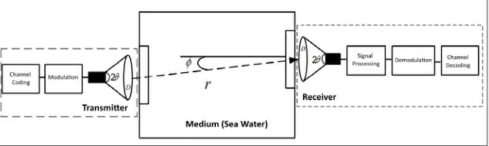
The diagram of the proposed model is given in Fig. 1. At the transmitter side, channel coding and modulation (QAM) is applied to the desired bits before transmission. After the laser generated light beam passes into the seawater, it enters the photo detector with being attenuated by the medium. Then the collimated signals undergo to signal processing to be amplified, demodulated and channel decoded respectively.
30
Fig.1. Proposed underwater optical communication link model
In the figure, ϕ is the angle of the optical axis between receiver and the line-of sight (LOS) of the transmitter, D is the aperture diameter of the receiver, θ is half angle transmitter beam width and r is the communication distance. As shown Fig. 1, the receiver and the transmitter of UWOC system are nearly located in the same axis. According to the proposed model, optical communication is affected by the attenuation of the light beam. Combining all the factors, the effective received power can be described as [4]; ( ) 2 2 2 cos( ) 4 tan ( ) C r T R P e D P r λ φ θ − = (3.1)
where 𝑃𝑃𝑇𝑇 is the transmitter power and 𝐶𝐶(𝜆𝜆) is the attenuation coefficient of the medium. Using eq. 3.1, the signal-to-noise ratio (SNR) at the receiver is given by; 2 ( ) 2 2 2 cos( ) 4 tan ( ) C r T P e D SNR r NEP λ φ θ − = (3.2) where NEP is the Noise Equivalent Power of the UWOC system which is related with the type of the receiver photodiodes. In this study, we choose APD type photodiode in the calculations. NEP can be described by the combination of different noise sources in the optical receiver (quantum shot noise, optical excess noise, background radiation noise, dark current noise, photo-detector excess noise and the thermal noise). In modeling, the combination of these noise sources can be considered as additive white gaussian noise (AWGN) [17-19]. In this work, the total NEP calculated by taking into the effect of major noise sources such as shot noise 𝜎𝜎𝑠𝑠𝑠𝑠2 , background noise 𝜎𝜎𝑏𝑏𝑠𝑠2 and dark current noise 𝜎𝜎𝑑𝑑𝑐𝑐𝑠𝑠2 where the noise variances are given by 2 2 2 sn bn dcn NEP= σ +σ +σ (3.3) 2 2 s sn h FP fυ σ η ∆ = (3.4)
UNDERWATER OPTICAL OFDM COMMUNICATION SYSTEM 2 2 bn h Ps fυ σ η ∆ = (3.5) 2 2 2 2 2 2 det 2 det 2 dark 2 dc dcn h I G F f h I f qG υ υ σ η ∆ + ∆ = (3.6)
where 𝑃𝑃𝑆𝑆 is the optical incoming power, h is Plancks constant, 𝜐𝜐 is the optical frequency of the signal, Δf is the effective noise bandwidth, F is the excess noise factor, η is the quantum efficiency of the photosensor, Ps is solar background power, 𝐼𝐼𝑑𝑑𝑑𝑑𝑑𝑑𝑑𝑑 is the multiplied dark is current, 𝐼𝐼𝑑𝑑𝑐𝑐 is the non-multiplied dark current and 𝐺𝐺𝑑𝑑𝑑𝑑𝑑𝑑 is the detector current gain.
In this work, choosing the underwater medium as homogeneous environment without the turbulence, the UWOC model can be considered as a linear time-invariant system [17] as 𝑦𝑦(𝑡𝑡) = ℎ(𝑡𝑡) ∗ 𝑥𝑥(𝑡𝑡) + 𝑛𝑛(𝑡𝑡) where x(t), y(t) are transmitted and received signals, h(t) is the impulse response of the channel and n(t) is the AWGN. * indicates the convolution operator and unlike [7,12], the time dispersion is not neglected in our channel model. Also,
the aperture diameter D is chosen as 50 cm radius for collecting more scattered photons. In addition, the delay spread 𝜏𝜏𝑠𝑠𝑠𝑠𝑑𝑑𝑑𝑑𝑑𝑑𝑑𝑑 of the channel is chosen to be longer than the duration of the sampling time 𝑇𝑇𝑠𝑠 of the OFDM symbol in time domain. Therefore, UWOC channel behaves like multi-tap fading channel.
For an OFDM system with N sub-carrier, the received signal in the frequency domain can be found as;
[ ] [ ]* [ ] [ ]
Y k =H k X k +Z k (3.7) where X[k] denotes the k-th sub-carrier frequency components transmitted symbol, Y (k) is received symbol, H[k] is channel frequency response and Z[k] is noise in frequency domain, respectively. The unknown channel frequency response should be obtained by using channel estimation algorithms. In this study, improve LS and proposed improved MMSE algorithms are compared. After the channel is estimated, the transmitted data is equalized by Zero Forcing (ZF) equalizer as;
{ }
n k k n n
X IFFT Y C y c
∧
32
where 𝐶𝐶𝑑𝑑 represents the equalizer correction term, which is computed according to the frequency domain equalization as follows [20];
1 k FFT C H ∧ = (3.9)
Then, the binary information data is obtained back in modulation and decoding respectively.
4. CHANNEL ESTIMATION
Comb-type plot arrangement is used for frequency domain interpolation to estimate channel frequency response [10,21] where every OFDM symbol has pilot tones that are periodically located at the each sub-carriers. It is important to notice that the periods of pilot tones in frequency domain must be placed in the coherence bandwidth. The coherence bandwidth is determined by an inverse of the maximum delay spread 𝜏𝜏𝑠𝑠𝑠𝑠𝑑𝑑𝑑𝑑𝑑𝑑𝑑𝑑.
Considering ˆ 1
LS
H =X Y− H , LS algorithm uses the weight matrix W to estimate the channel such as Hˆ WH. However, in MMSE channel estimation weight matrix is found by forcing the cross-correlation ReH of the error vector e and the channel estimate H to zero. Therefore, W is found as [22];
1
HH HH
W =R R− (4.1)
Using eq. 4.1, MMSE channel estimate can be found as;
ˆ
HH HH
H=WH =R R H (4.2)
As shown in Fig. 2, MMSE channel estimation can be improved by introducing an FFT based algorithm. An important point is that 𝜏𝜏𝑠𝑠𝑠𝑠𝑑𝑑𝑑𝑑𝑑𝑑𝑑𝑑 must be known formerly to remove the effect of noise from the channel delay. After taking the IFFT of the MMSE channel, 𝐻𝐻� is estimated in the time domain. Then the coefficients contain the noise are ignored with zero
UNDERWATER OPTICAL OFDM COMMUNICATION SYSTEM
padding. This is followed by transforming the remaining 𝜎𝜎𝑚𝑚𝑑𝑑𝑚𝑚 elements back to the frequency domain to achieve HFFT
∧
which is used in eq. 3.9 at the Frequency Domain ZF Channel Equalizer.
Fig.2 FFT-based MMSE Channel Estimation 5. SIMULATION RESULTS
In this section, BER performance and Mean Square Error (MSE) of the studied systems are shown. The simulation parameters are compliant to the underwater wireless optical channel model as 1 GHz bandwidth, 16 QAM constellation, 512 sub-carriers, 384 occupied sub-carriers, 16 cyclic prefix length and 128 pilot tone number. For the channel model, multipath fading channel is used by modeling as a 2 tapped-delay line with choosing 𝐿𝐿𝑐𝑐ℎ= 2 and the delay taps as [0 3] ns. Furthermore the channel gains of the taps are chosen as [-0.65 -22] dB.
In Fig. 3, performance of the LS, MMSE and their DFT based improved channel estimation techniques are compared. While the graphs on the left side shows linear, spline interpolated LS estimation and MMSE estimation without DFT technique, the graphs at the right side the DFT based estimations are located with the same manner. The MSE values of each LS-linear/LS-spline/MMSE Channel Estimation are 1.3902*10 -2/1.7638*10-2/2.4308*10-3 and the MSE values of DFT based LS-linear/LS-spline/MMSE Channel Estimation are 4.9253*10-4/4.8932*10-4/1.7816*10-3
34
at 30 dB respectively. The MSE results shows that the DFT based channel estimation method improves the performance of the channel estimation. Also, according to the results, it is clear that the MMSE estimation shows better performance than the LS estimation.
Fig.3 Performance comparison of the LS (with linear (a) and spline (b) interpolation), DFT based LS (d-e), MMSE (c) and DFT based MMSE (f) channel estimation algorithms
The received signal constellation before and after the channel compensation for the OFDM system with 16-QAM at 30 dB SNR value are shown in Fig. 4. The correction effect of the DFT based estimation is illustrated at the right side.
In Fig. 5 the BER performances are compared for the LS with linear and spline interpolation, DFT based LS and DFT based MMSE and DFT based LS channel estimation algorithms. According to the results, MMSE channel estimation has better performance than the LS channel estimation. Also, introducing the DFT structure into the channel estimation algorithms improves the performance for both LS and MMSE estimators. The results
UNDERWATER OPTICAL OFDM COMMUNICATION SYSTEM
also show that, improved MMSE channel estimation has the lowest BER rates for the SNR range between 0 and 30 dB.
Fig.4 Received signal constellation before (left) and after (right) channel compensation
36
Fig.5 BER performance comparison of the LS (linear and spline), MMSE and DFT-based MMSE and DFT-based LS (linear and spline) channel estimation with respect to SNR
6. CONCLUSION
As the necessity of a reliable channel with high data rates increases in the underwater communication, a search for algorithms that can compensate the noise generated by the medium becomes an important issue. As an alternative solution to this problem, an improved MMSE based estimation algorithm is proposed in this paper for the coherent wireless underwater optical OFDM communication systems. Comparing with the LS and modified LS based algorithms that are studied in the literature, the proposed method showed better performance for low SNR values. For the next step, the proposed method should be studied in the real time applications.
REFERENCES
[1] H. Brundage, Designing a wireless underwater optical communication system, (Massachusetts Institute of Technology, M.S. thesis, 2010). [2] X. Yu, W. Jin, M. Sui and Z. Lan, Third International Conference on
Communication and Mobile Computing (CMC), (2011) 527-530. [3] J. Simpson, A 1 Mbps Underwater Communication System using
LEDs and Photodiodes with Signal Processing Capability, (NC State University, M.S. Thesis, 2008).
[4] V.I. Haltrin, Applied Optics, 38/33 (1999) 6826-6832.
[5] C.D. Mobley, Handbook of Optics, (McGraw-Hill, Inc., 1994). [6] S. Arnon and D. Kedar, Journal of the Optical Society of America A,
26/3 (2009) 530–539.
[7] C. Gabriel, M. Khalighi, S. Bourennane, P. Leon, and V. Rigaud, Proc. IEEE GLOBECOM Workshop, (2011) 833–837.
[8] S. Jaruwatanadilok, IEEE Journal on Selected Areas in Communications, 26/9 (2008) 1620–1627.
[9] F. Hanson and S. Radic, Applied Optics, 47/2 (2008) 277-283. [10] J.H. Smart, IEEE Military Communications Conference (2005)
1140-1146.
[11] J.W. Giles and I.N. Bankman, IEEE Military Communications Conference (2005) 1700–1705.
UNDERWATER OPTICAL OFDM COMMUNICATION SYSTEM
[12] C. Gabriel, M. Khalighi, S. Bourennane, P. Leon, and V. Rigaud, Journal of Optical Communications and Networking, 8/1 (2013) 1-12. [13] P.I. Minev, C.C. Tsimenidis and B.S. Sharif, OCEANS, 2012 - Yeosu,
(2012) 1-5.
[14] S. Zhang, C.L. Bai, Q.L. Luo, L. Huang and F.F. He, Optik - International Journal for Light and Electron Optics, 124/23 (2013) 5937–5940.
[15] Z.R. Tong, M. J. Guo, X.F. Yang and W.H. Zhang, Applied Mechanics and Materials, 130 (2012) 2965-2968.
[16] S.K. Gupta, Defense Science, 34/1 (1984) 19-28.
[17] R.C. Smith and K.S. Baker, Applied Optics, 20/02 (1981) 177-184. [18] A. Morel, Journal of Geophysical Research: Oceans, 93/C9 (1988)
10749-10768.
[19] M. Lanzagorta, Underwater Communications. Synthesis Lecture on Communications, (Morgan Claypool publishers, 2012).
[20] S. Coleri, M. Ergen and A. Puri, A., IEEE Transactions on Broadcasting, 48/3 (2002) 223-229.
[21] G.R. Osche, Optical Detection Theory for Laser Application, (Wiley-Interscience, New Jersey, 2002).
[22] Y. Shen and E. Martinez, Channel Estimation in OFDM Systems, (Freescale Semiconductor:Application Note, 2008).