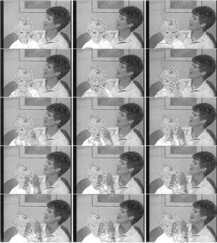
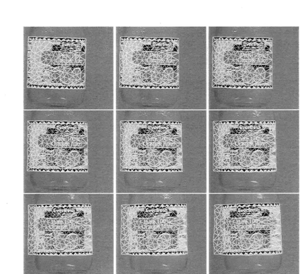
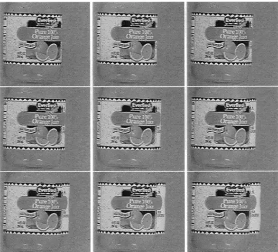
PROCEEDINGS OF SPIE
SPIEDigitalLibrary.org/conference-proceedings-of-spieTwo-dimensional triangular
mesh-based mosaicking for object tracking
in the presence of occlusion
Candemir Toklu
A. Murat Tekalp
A. Tanju Erdem
2-D TRIANGULAR MESH-BASED MOSAICKING FOR
OBJECT TRACKING IN THE PRESENCE OF OCCLUSION'
Candemir Toklu, A. Murat Tekaip and A. Tanju Erdem
Department of Electrical Engineering and Center for Electronic Imaging Systems University of Rochester, Rochester, NY 14627. (toklu,tekalp©ee.rochester.edu)
t Electrical and Electronics Engineering Department, Bilkent University, Ankara, Turkey. (tanju©ee.bilkent.edu.tr)
ABSTRACT
In this paper, we describe a method for temporal tracking of video objects in video clips. We employ a
2-D triangular mesh to represent each video object, which allows us to describe the motion of the object by
the displacements of the node points of the mesh, and to describe any intensity variations by the contrast and brightness parameters estimated for each node point. Using the temporal history of the node point locations, we continue tracking the nodes of the 2-D mesh even when they become invisible because of self-occlusion or occlusion by another object. Uncovered parts of the object in the subsequent frames of the sequence are detected by means of an active contour which contains a novel shape preserving energy term. The proposed shape preserving energy term is found to be succesful in tracking the boundary of an
object in video sequences with complex backgrounds. By adding new nodes or updating the 2-D triangular mesh we incrementally append the uncovered parts of the object detected during the tracking process to the
one of the objects to generate a static mosaic of the object. Also, by texture mapping the covered pixels into the current frame of the video clip we can generate a dynamic mosaic of the object. The proposed
moaicking technique is more general than those reported in the literature because it allows for local motion and out-of-plane rotations of the object that result in self-occlusions. Experimental results demonstrate the successful tracking of the objects with deformable boundaries in the presence of occlusion.
1 INTRODUCTION
Many multimedia applications, such as augmented reality, bitstream editing and interactive TV,
de-mand object-based video modeling. Furthermore, the ongoing MPEG-4 standardization efforts are aimed at
compression algorithms that support object-based functionalities,' such as object-based scalability, where different objects can be coded at different bit rates and can be reconstructed selectively by decoding sub-sets of the entire bitstream. For instance, it is possible to decode and reconstruct only the players in a video clip of a tennis match, if the clip is compressed using a object-based representation. Spatiotemporal
evolution of image objects can be described by estimating their motion and intensity variations throughout
time. Therefore accurate tracking of the boundary and the local motion and intensity is an important part
of object-based video representation and compression.
This paper addresses tracking of 2-D deformable objects with deformable boundaries in the presence of
another occluding object or self-occlusion. Here we propose a method to handle objects which appear in
multiple pieces and newly uncovered regions of an object. Using temporal history of the object we recovered the occluded nodes of the 2-D mesh which return to visible state and continue tracking them. The proposed method can construct a mosaic of the object as the object is being tracked, and at the same time uses mosaic
'This work is supported in part by a National Science Foundation SIUCRC grant and a New York State Science and
Technology Foundation grant to the Center for Electronic Imaging Systems at the University of Rochester, and a grant by Eastman Kodak Company.
being constructed to track the objects in a subsequent frame. Possible uncovered parts of the object that are detected as the object is tracked throughout the image sequence are appended to the object in the first frame for obtaining the static mosaic of the object. It can be noted that by texture mapping the covered
pixels into the current frame of the video sequence one can generate a dynamic mosaic of the object as well. The proposed moaicking technique is more general then those given in2 because it allows for local motion
as opposed to global transformations of the object and out-of-plane rotations of the object that result in
self-occlusions. Uncovered parts of the object in the subsequent frames of the sequence are detected by means of a novel energy minimizing active contour which tries to preserve the shape of the object while snapping to nearest intensity edges. Shape preserving energy is found to be succesful in tracking the boundary of the object in the video sequences with complex backgrounds. It is well known that the accuracy of the boundary tracking play an important role in the visual quality of object-based video compression and bitstream editing. The proposed active contour modeling provide a greater flexibility in tracking the deformations of the object boundary compared with so-called "curved triangles" method.3
In Section 2, we present a review of the motion tracking techniques that currently exists in the literature. The details of the proposed tracking and mosaicking method are discussed in Section 3. Experimental results are provided in Section 4 to demonstrate the effectiveness of the proposed method in real life applications. Finally, concluding remarks are given in Section 5.
2 LITERATURE REVIEW
Existing methods for object tracking can be broadly classified as boundary (and thus hape) tracking, and region tracking methods. Boundary tracking has been addressed using a locally deformable (active)
contour model4 (snakes5), and using a locally deformable template model.6 Region tracking methods can be categorized into those that employ global deformation models7 and those that allow for local deformations.
One region tracking method8 uses a single affine motion model within each region of interest and assigns a second-order temporal trajectory to each affine model parameter. However, none of the aforementioned boundary or region tracking methods address tracking the local motion of the object. Local deformations
within a region may be estimated by means of dense motion estimation or 2-D mesh-based representations. The mesh models describe the motion field as a collection of smoothly connected non-overlapping patches.
However, prior work in mesh-based motion estimation and compensation912 do not address tracking an arbitrary object in the scene, because they treat the whole frame as the object of interest.
In one of the earlier works,'3 we model the boundary of the object by a polygon with a small number of vertices, and its interior by a uniform mesh under the assumption of "mild" deformations. We employ a novel generalized block matching method at the vertices of the polygon to predict the location of the
mesh in the subsequent frames of the image sequence. The motions of each mesh node is linearly predicted from the displacements of the vertices and then refined using a connectivity preserving search strategy. In a subsequent work,14 the boundary of the object is modeled by an active contour (uniform B-spline) to better
track its deformations, where improved motion estimation and triangulation methods are also employed to
handle occlusions. However, our preliminary results14 show that if there is another occluding object which
splits the object-to-be-tracked into multiple pieces, tracking may be lost. Also in the case of a foreground object moving in front of the object-to-be-tracked with a different motion, the mesh structure within the
330
3 METHOD
We assume that the user manually selects the contour enclosing the object to be tracked in the first frame
of the video sequence. This contour is snapped to the actual boundary on the first frame of the sequence using energy minimization. A content-based adaptive mesh,'2 is then fit within the object boundary. This mesh is called the reference mesh. Each node of the reference mesh is either a corner or an inside node,
which are located on or inside the object boundary, respectively. Image region in the first frame covered by
the reference mesh is taken as the object mosaic. At each frame, the image region covered by the mesh on that frame is assumed to be the warped and/or occluded version of the mosaic object. Given the reference mesh and the object mosaic, the following steps are carried out to track and construct the object mosaic:
A. Finding the object-to-be-covered (OTBC) regions in the current frame
We estimate forward dense motion field inside the object boundary in the current frame. One can use his/her favorite motion estimation method at this step which produces a dense motion field. Using the
forward dense motion field we compute the Displaced Frame Difference (DFD) within the object boundary
and threshold it to obtain the OTBC regions. We model the residuals using a contaminated Gaussian
distribution, where the residuals for the covered regions are contaminants. We then derive an estimate of the standard deviation o of the Gaussian distribution from the median value of the absolute residuals. Given the random samples from a Gaussian distribution with a given a, a commonly used estimate of aisthe median absolute deviation
o
= 1.4826median(,)sIr(i,j) —
median(k,l)Es(r(k,l))I, (1)where r(i, j) =DFD(i,j) and (i, i) is a pixel inside S, the region covered by the mesh in the current frame.
The estimate of the standard deviation, , can be found in linear time from the residuals. We set error
threshold to a factor, typically 2.0, of the computed o.
At any time instant, each node of the mesh is labeled as "occluded" or "visible." The visible nodes that
fall inside the OTBC regions in the current frame are labeled as occluded. The labels for the nodes that are
already occluded are not changed at this step. B. Predicting the mesh in the next frame
For predicting the location of the visible nodes in the next frame, we sample the dense motion field. The
locations of the occluded nodes in the next frame are predicted by looking to node location histories and
fitting an affine motion trajectory model in the least squares sense.
Let (x, y)(t) denote the image coordinates of node at time instant t. The 2-D affine motion of a point with an affine model can be written as
(t) —— a1(t) a2 (t)
x
a3 (t) 2a4(t) a5(t) )
+
a6(t)If we expand (x, y) (t + 1) in Taylor series and drop the second-order terms we obtain
[
] (t+1)=
[
] (t)+St[
],
(3)where 6t is the time step between two consecutive frames. From (2) and (3) we get
x (j
+
— 1+ öta1 (t) 5ta2 (t)x
a3 (t) 4Looking at the history of the occluded node, a(t), i = 1, •• • , 6'sare solved in the least squares sense.
Then, using (4) the location of the occluded node in the next frame is predicted. For the first several frames
of the image sequence, until sufficient node history builds up, the location of the occluded nodes can be linearly interpolated from the displacements of the visible nodes that are linked to them in the mesh.
The mesh reconstructed in the next frame is called the moved mesh. C. Finding the 'unovered object (UO) regions in the next frame
We reconstruct the object in the next frame by warping the mosaic object and compute the DFD in the next frame. From the residuals, r(i, j) = DFD(i, j), a new threshold value is computed and used to obtain the covered regions of the object in the next frame. Nodes are relabeled such that they are labeled as occluded if they fall into covered regions or visible otherwise. From the corner nodes of the mesh the
predicted boundary of the object in the next frame is obtained. The boundary is then snapped to the nearby
image edges. In this paper we present novel energy terms for snakes (energy minimizing active contours)
which are used for boundary tracking. We employ a B-spline formulation for the snakes. A B-spline curve is defined by its control points as
v(s) = pB(s —
i)
= PTB, 0 s S
(5)where B is the vector of the B-spline basis functions with element B(s —
i)
and p is the ith B-spline control point and v(s) = [x(s)y(s)]T is the parametric description of the snakes's shape. We will let C denote the contour associated with the snake. Thus, C = {v(s) : 0 s sf}. Then the snake energy is defined as thecontour integral of the snake energy density snake
Is'
Esnake = I Esnake(V(S))dS, (6)
Js=o
Thesnake energy density snake 5 defined in a way that minimization of Esnake results in a contour C that
corresponds to the boundary of the object of interest. We write the snake energy density as a sum of an internal energy density et and an external energy density text:
fsnake(V(S)) = e(v(s)) + fext(t'(S)) (7) The internal energy of the snake is composed of stretching, smoothness, area, local shape preserving and equidistance terms where
2 dy(s)
eien(y(s)) = aienllVs(5)II ' y5(s)= —a-———, (8)
2 d2v(s)
€curv(V(S)) = cxcurvllVss(S)ll y55(s) = ds2
dy dx
earea(y(s)) = aarea(x(s) —
djst adSt(IIP —p+iII —d) 6shape = ashapellV(5) —T(Vref(5))112.
The first term tries to minimize the length of the contour. The second term forces a smooth contour
generation since IIv5(s)dsII defines the curvature of the contour at s. The third term corresponds to a
potential in the normal direction of the contour at s and it forces the contour to either shrink or expand.
The fourth term forces the control points to be equally spaced with an average distance of d. The fifth term
which is always selected as the object boundary in the previous frame. Our formulation allows computation
of both local and global spatial transformations. We found the local transformation calculation to be more
effective.
The external energy of the snake is composed of only the edge energy where
6edge (v (s)) =aedge,1IIVI(v(s)) I12+ ad9,2 [V21(v (s))]2. (9)
We employ a numerical greedy search approach'5 for finding the best (i.e., the minimum energy) shape of the snake. For each control point, energies of all the possible pixels in a window centered at the control point are calculated and the best location with the minimum energy is defined as the new location of the
control point. B-spline formulation of the snake allows us to locally change the density coefficients, a's. For
the control points of the snake that fall inside the covered region in the next frame the external energy is
killed and only internal energies are kept. The spatial transformation for the shape energy density is solved
in the least squares sense from the displacements of the neigboring control points from the corresponding control point locations in the previous frame and is local. In our current implementation we use a rigid transformation, translation, rotation and zoom only, and use the current, previous and next control points
to solve for the parameters of the affine transformation.
The image regions that remain inside the snapped boundary but outside the predicted boundary are
identified as the UO regions.
D. Updating the reference and the moved meshes
Given the UO regions, the visible corner nodes of the moved mesh are pulled onto object boundary such that their new location minimizes a predefined cost function. Every corner node that falls outside the object
boundary is pulled to the nearest point on the boundary. On the other hand, every visible corner node that falls inside the object boundary is pulled to a point on the boundary such that (i) the node is close to its previous position, and (ii) the distance between the points which are obtained by mapping the corner node into the object mosaic by the affine mappings of the triangles where the node is a vertex of the triangles is minimum. These affine mappings are used to predict the location of the corner node in the object mosaic. If the length of mesh edges gets larger than a factor of the average edge length, typically 2, the two mesh
patches that share this edge are divided into four smaller patches and a new node is created at the midpoint
of the edge in consideration. Due to the sharp deformations of the object boundary new corner nodes on the boundary are selected and a new patch either can be appended to the mesh or the nearest patch to this
new corner node can be divided into two to create new patches. E. Updating the object mosaic
Using the constrained Hexagonal Search,'3 we refine the corner nodes of the reference mesh and the inside nodes of the moved mesh such that the intensity prediction error within the object boundary in the
next frame is minimized. Since covered regions and the UO regions in the next frame are known, intensity differencences within these areas can be assumed to be zero during the mesh refinement process. Given the
refined reference and the moved meshes, the intensity distribution within UO regions are warped into the
object mosaic.
4 EXPERIMENTAL RESULTS
A. Deforming video object occluded by another object
We have used the sequence "Mother & Daugther" for testing the performance of our tracking algorithm
in the case of a deforming video object which is occluded by another object. The "Daugther object" is designated as the object to be tracked. Note that this object is occluded by the entry of mother's hand into the scene. Since the mother's hand moves very fast, there is significant motion blur in some of the frames.
Furthermore, the mother's hand shades the Daugther object and the shade is also moving.
The boundary of the Daugther object is outlined by an interactive drawing tool in the first frame of the
sequence. In Fig. 1, we show the tracked meshes and the boundaries of the detected occlusion areas overlaid
on the Daugther object in frames 56, .. . , 70in raster scan order. Occlusion region boundaries are depicted in black in this figure. The mother's hand enters the scene in the 58th frame of the sequence and moves very
fast until the 65th frame.
Our method have successfully tracked the boundary and the local motion of the object. The hand, the shade of the hand and the closed eyes are detected as occlusion areas. Node point locations remained consistent even with large motion and motion blur. However, most of the shaded areas are detected as
occlusion regions and we are still working on reducing the occlusion areas due to shading using the intensity
variation model introduced in.13 Since the hand and the Daugther objects have almost uniform textures, contrast and brightness parameters tend to match hand color to shirt color.
B. Rigid curved object going through an out of plane rotation
We demonstrate the performance of the proposed approach in the case of out of plane rotations. The
test sequence is called "Rotating Bottle" and is recorded by a rigid Hi-8 mm comsumer camcorder while the object is rotating in front of a stationary background. Interlace-to-progressive conversion of the sequence is done by spatially interpolating the even fields to frame resolution (300 lines by 330 pixels). The sequence is
very noisy and due to the transparent nature of the object and the background colors, the information on the bottle that is to be tracked is low in contrast. Therefore we have provided the boundary of the object in each frame of the video clip as an input to our tracking/mosaicking algorithm. In Fig. 2, we show the tracked meshes overlaid on the frames 2, .. . , 10 in raster scan order. The static mosaic object created is
displayed in the same frames in Fig. 3. In this particular experiment we did not refine the corner points of the mesh and kept the mesh size large, hence the discontinuities at the boundaries of the object.
5 CONCLUSION
The proposed object tracking and mosaicking approach has been found to be effective in tracking objects
with deformable boundaries and local motion in the presence of occlusion. This method can be used in
object-based video coding and animation. Using texture warping a decoder can reconstruct the subsequent frames of the sequence given the node point motion displacements, uncovered object region boundaries and texture of the reference frame. Given enough number of views of a similar new object the tracked object in the video clip can be changed with the new object.
Work is under progress to detect more efficiently the uncovered object regions which is an important part of the method. We are also looking at ways of improving the performance of the method in self occlusion,
334
6 ACKNOWLEDGMENTS
We would like to thank to Dr. J. Riek and Dr. S. Fogel of Eastman Kodak Company and Dr. P. J. L. van Beek for their contributions to the software used in this work.
7 REFERENCES
[1] MPEG-4 Call for Proposals. ISO/IEC JTC1/SC29/WG11 N0997, July 28 1995.
[ 2] M. Irani, P. Anandan, and S. Hsu. Mosaic based representation of video sequences and their applications. In mt. Conf. Computer Vision, pages 605—611, Cambridge, MA, June 1995.
[3] K. Schröder. Description of moving 2d-objects using a grid based on curved triangles. In Workshop on Image Analysis and Synthesis in Image Coding, Berlin, Germany, October 1994.
[4] B. Bascle and et al. 'Lacking complex primitives in an image sequence. In mt. Conf. Pattern Recog.,
pages 426—431, Israel, Oct. 1994.
[ 5] M. Kass, A. Witkin, and D. Terzopoulos. Snakes: active contour models. mt. Journal of Comp. Vision,
1(4):321—331, 1988.
[ 6] C. Kervrann and F. Heitz. Robust tracking of stochastic deformable models in long image sequences.
In IEEE mt. Conf. Image Proc., Austin, TX, November 1994.
{7] Y. Y. Tang and C. Y. Suen. New algorithms for fixed and elastic geometric transformation models. IP,
3(4):355—366, July 1994.
[8] F. G. Meyer and P. Bouthemy. Region-based tracking using affine motion models in long image
se-quences. CVGIP: Image Understanding, 60(2):119—140, Sept. 1994.
[ 9] Y. Nakaya and H. Harashima. Motion compensation based on spatial transformations. IEEE Trans.
Circuits and Syst. Video Tech., 4(3):339—357, June 1994.
[ 10] Y. Wang and 0. Lee. Active mesh-a feature seeking and tracking image sequence representation scheme. IEEE Trans. Image Processing, 3(5):610—624, Sept. 1994.
[11] R. Szeliski and H.-Y. Shum. Motion estimation with quadtree splines. Technical report, 95/1, Digital
Equipment Corp., Cambridge Research Lab, Mar. 1995.
[12] Y. Altunbasak and A. M. Tekaip. Occlusion-adaptive 2-d mesh tracking,. In IEEE mt. Conf. Acoust., Speech, and Signal Proc., Atlanta, GA, May 1996.
[13] C. Toklu, A. T. Erdem, M. I. Sezan, and A. M. Tekalp. 2-D mesh tracking for synthetic transfiguration,. In IEEE mt. Conf. Image Proc., volume 3, pages 536—539, Washington, DC, Oct. 23-25 1995.
[14] C. Toklu, A. M. Tekalp, A. T. Erdem, and M. I. Sezan. 2-D mesh-based tracking of deformable objects with occlusion,. In IEEE mt. Conf. Image Proc., Lausanne, Switzerland, Sept. 16-19 1996.
[15] D. Williams and M. Shah. A fast algorithm for active contours. In mt. Conf. Computer Vision, pages
Figure 1: The tracked meshes overlaid onto the frames onto the Daugther object in frames 56, '- , 70, in
336
Figure 2: The tracked meshes overlaid onto the frames onto the Bottle object in frames 1, ,9 in raster
:
ts