13th International Conference on Mathematical Methods in Electromagnetic Theory September 6 – 8, 2010, Kyiv, Ukraine
CALCULATION OF RADOME-ENCLOSED APERTURE ANTENNA IN 3-D
I. Sukharevsky 1, A. Altintas 21
A. Ya. Usikov Institute of Radiophysics and Electronics of NAS of Ukraine, 12, Academician Proskura St., Kharkov 61085, Ukraine
2
Bilkent University, Ankara, 06800, Turkey e-mail: [email protected]
Abstract– The exact mathematical model of an aperture antenna and the image theory are used to develop exact and
PO integral representations of the fields radiated by radome-enclosed aperture antenna. The desired problem is reduced to finding fields of a plane wave diffracted on the "symmetrized" radome. The passage of the wave through the wall of the radome is analysed by means of geometrical optics. Caustic influence is taken into account, and the contribution of stationary phase points of reflected field to the far-side radiation is discussed. Radiation patterns for antennas with a specified ampliphase distribution enclosed in spherical and parabolic radomes are analysed.
I. INTRODUCTION
Aperture antennas in the presence of a radome have been studied in various works. However, the vast majority of aperture approximations do not provide valid results for far sidelobes. A mathematically strict model [1] presents an aperture as a hole in an ideally black screen. The generalised image principle [2] allows to calculate the fields radiating by antenna to the semispace in the presence of arbitrary scatterers (dielectric, conducting or magnetic). In this formulation, problem is reduced to the diffraction of a plane wave on the "symmetrized" radome. The similar “symmetrized” model was used, for example, in [3] for simulating of a radome-enclosed dipole array backed by a ground plane in 2-D, and in [4] for representations of the fields of an aperture antenna enclosed in a spherical chiral radome.
For 3-D modelling of large dielectric radomes, asymptotic algorithms are considered to be more suitable. Reflections from the inner walls of the radome usually cause significant pattern deformations and increase sidelobe levels. The wave passage through the radome layer is calculated with a conventional GO method. However, the caustic influence on the fields reflected from the radome is taken into account. The stationary phase points of the reflected field are detected in order to estimate their contribution to the far-side radiation.
Radiation patterns of antenna with a given amplitude-phase excitation law are presented for spherical and parabolic radomes.
II.BASIC REPRESENTATIONS OF FIELDS
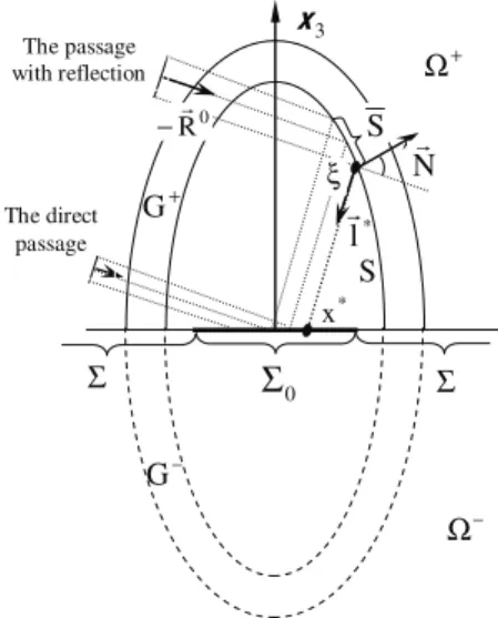
Let aperture Σ0 is in the plane x3=0 and radiates to the semi-space Ω (+ x3>0) (Fig. 1). Radiated field )
( ), (x H x
E& & is induced by some sources in semi-space Ω (− x3<0). Domain Ω contains dielectric radome +
+
G with permittivities ε(x),μ(x). Consider two assumptions about the physical properties of surface Σ:
A – Σis the ideally conducting surface ( =0
Σ
t
E& );
B – Σ is the ideally magnetic surface ( =0
Σ
t
H& ).
Denote (E&A,H&A)and (E&B,H&B) for the fields induced by aperture in domain Ω in problems A and B. + Consider also their half sums:
13th International Conference on Mathematical Methods in Electromagnetic Theory September 6 – 8, 2010, Kyiv, Ukraine
° ° ¯ °° ® + = + = ). ( 2 1 ), ( 2 1 B A C B A C H H H E E E & & & & & & (1)
“Averaged” field (1) can be interpreted as a field corresponded to Macdonald’s model [5] of ideally black surface Σ . Using Lorentz lemma and generalized principle of mirror images [2], derive for any point x0∈Ω+
and any vector p&:
( )
(
( )
(
,)
( )
(
,)
)
, 0 0 1 0 1 0 E x H xx p H x E xx p dS x E pj & &C
³
&A & & &B & & &Σ × − × = ⋅ ω (2)
wheredS&=n&dS,n& is the unit vector, normal to S and directed to 0 Ω ; − E&1,H&1is electromagnetic field induced by a point source (electric dipole) in a space containing a closed dielectric shell, which is symmetrical with respect to plane x3= (Fig. 1). 0
From exact formulae (2) go to the approximation of physical optics. When edge effects in the aperture are small, ),
( )
(x E x
E&A ≈ &B H&A(x)≈H&B(x). Then, omitting indices A, B, we get:
( )
(
( )
(
,)
( )
(
,)
)
, 0 0 1 0 1 0 E x H xx p H x E xx p dS x E pj & &C
³
& & & & & & &Σ × − × = ⋅ ω (3)
Right-hand integral (3) expresses field of the radiating aperture through the given distributions Et,Ht
& &
in the aperture and field, diffracted on the “symmetrized” radome. Eq. (3) means that in inhomogeneous medium the field, calculated by the method of equivalent currents, coincides (in PO approximation) with “averaged” field of Macdonald model. Thus, these formulae generalize results of [1] for the case of inhomogeneous medium. From (2), (3) obtain formulae for complex directivity pattern of radiating system E&(R&0), where R&0 is a unit vector of an observation point in far-zone:
Σ Σ
Σ
0 + G S 3 x S 0 R& − ξ N& * x * l & The passage with reflection The direct passage + Ω − Ω − G13th International Conference on Mathematical Methods in Electromagnetic Theory September 6 – 8, 2010, Kyiv, Ukraine
( )
R(
E( )
x H(
x R p)
H( )
x E(
x R p)
)
dS Ep
j & &C &
³
&A & & & &B & & & &Σ × − × = ⋅ 0 , 0 1 , 0 1 0 , , ω – exact formulae;
j &p E&C
( )
R&³
(
E&( )
x H&(
x R& p&)
H&( )
x E&(
x R& p&)
)
dS&Σ × − × = ⋅ 0 , 0 1 , 0 1 0 , , ω (4)
– approximate PO formula; E&,H& is aperture distribution of tangential field in Kirchhof‘s approximation;
1
1, H
E& & is a field of a plane wave E&0, H&0 propagating in the direction−R&0, which passed through the radome; , ) ( 0 ( ) 0 0 0 0R x ik e R p R E & & & & & & − ⋅ × × = ( ) ( ), 0 0 0 0 0 0 R x ik e R p H & & & & & − ⋅ × = μ ε
where ε0,μ0,k0are permittivities and a wavenumber in free space, respectively.
Assume H&1
(
x,R&0,p&) (
,E&1x,R&0,&p)
as a sum of the field reflected from the inner wall S of the radome and the field passed through the radome directly to the aperture (Fig. 1). Multi-reflections provide scattered field corrections of a higher order, so can be neglected due to electrically large sizes of the radome.III.ON THE PLANE LAYER APPROXIMATION OF THE RADOME SURFACE
As is shown in part II, our problem is reduced to the plane wave passage though the radome surface. For this purpose, approximation of the curved radome surface by a plane layer is widely used. However, the correctness of such approximation with respect to different values of radome thickness and curvature was usually not considered. We have compared transmission coefficients in the first, second, and the third-term asymptotic approximation of the GTD algorithm [6], and the following conclusions can be made:
1) When 0 0 10 ~ 1 λ
κ geometrical optics approximates the field on the external surface of an equidistant
layer quite well (with amplitude error ~0.5%); the second asymptotic term gives result, which is not corrected byt the further terms.
2) When 0 0 2 ~ 1 λ
κ errors in the GO representation may arise up to 5-8%. Second-term asymptotic formulae
are practically exact in this case (errors ~0.3-0.5%).
3) The case 0
0
~ 1
λ
κ is already critical for the formulae of second-term asymptotic approximation.
It is to be noted that the first term of the considered approximation is exactly GO flat-layer approximation of the curved dielectric layer. This should be taking into account when modeling wave transmission through the radome.
IV.NUMERICAL RESULTS
Consider circular aperture of radius 5λ (0 λ is the wavelength in the free space) with cosine-law amplitude 0 distribution (represented by Et,Ht
& &
in (4)) placed symmetrically to the axis of a parabolic radome, whose surface equation is . h ) x x ( P x =− 12+ 22 + 0 3 2 1
13th International Conference on Mathematical Methods in Electromagnetic Theory September 6 – 8, 2010, Kyiv, Ukraine
Parameters of the radome are: P0 =1.4λ0,the depth of the radome h=5.56λ0,the dielectric permittivity ,
7
1 =
ε and the thickness is matched for the normal incidence. The unit polarization vector of currents in the
aperture is p&0=(0,1,0) ( t e(qx)
x x cos p
E& = & π + &⋅&
2 2 2 2 1 0 ).
Using formula (4) we calculated radiation patterns in H-plane (p&=(0,1,0),R&0 =(sinγ,0,cosγ); Fig. 2) and compared them with the radiation patterns of the aperture enclosed in a semi-spherical radome, whith radius
0
56
5 λ
= .
r . Scanning was carried by vector q&=(sinα,0,cosα). All radiation patterns were normalized to the maximum of the radiation pattern without a radome.
Note, that the radiation pattern of a circular aperture without electrical scanning (Fig. 2 (a)) coincides with the corresponding pattern of [7], where it was computed by exponential approximation of Bessel function.
A significant increasing of the sidelobe level in the far zone is observed in comparison with the radiation pattern of an aperture without radome in H-plane. Far sidelobes grow by 15-20 dB.
The radiation pattern for a semi-spherical radome is much more distorted compared to a parabolic radome for the case of a cosine-law distribution; however, this effect is less explicit for a constant amplitude and phase distribution (Fig. 2 (b)). -100 -90 -80 -70 -60 -50 -40 -30 -20 -10 0 -90 -70 -50 -30 -10 11 31 51 71 ANGLE (DEG) NOR M AL IZ E D P A T T E R N (d B ) -100 -90 -80 -70 -60 -50 -40 -30 -20 -10 0 -90 -70 -50 -30 -10 11 31 51 71 ANGLE (DEG) NOR M AL IZ E D P A T T E R N (d B )
Fig. 2. Radiation patterns of the circular aperture antenna with the parabolic radome (black line), the semi-spherical radome (black dashed line), and without radome (grey line) in H-plane. (a) without scanning for cosine amplitude distribution. (b) scanning under an angle of 50
for cosine amplitude distribution.
REFERENCES
[1.] Ya. N. Feld, “ Calculation of the fields of the aperture antennas” Radiotekh. Electron., vol. 26, pp. 178-183, 1981 (in Russian; transl. by Radio Engineering and Electronic Physics).
[2.] I. V. Sukharevsky, and O.I. Sukharevsky, “Calculation of a field induced by the radiating aperture in the presence of arbitrary system of scatterers,” Radiotekh. Electron., vol. 1, pp. 8-13, 1986 (in Russian; transl. by Soviet Journ. of Commun. Technology and Electronics).
[3.] W.-J. Zhao, Y.-B. Gan, C.-F. Wang, and L.-W. Li, “Radiation pattern and input impedance of a radome-enclosed planar dipole array backed by a ground plane,” Antennas and Prop. Symp. 2005, vol. 1A, pp. 350-353, 3-8 July 2008. [4.] Li, M.-S. Leong, P.-S. Kooi, T.-S. Yeo, Y.-L. Qin, “Radiation of an aperture antenna by a spherical-shell chiral radome and fed by a circular waveguide,” IEEE Trans. Antennas Propag., vol.46, no. 5, pp. 664–671, May 1998.
[5.] H. M. Macdonald, Phil.Trans. Sec. A, 1912, v.12, no. 212, p. 337.
[6.] I. V. Sukharevskii, “Passage of electromagnetic waves through a radio-transparent layer,” Radio Engineering and Electronic Physics, vol. 12, pp. 191-197, Feb. 1967.
[7] E.J. Rothwell, “Exponential approximation of Bessel functions, with applications to electromagnetic
scattering, radiation and diffraction,” IEEE Antennas and Prop. Magazine, vol. 51, no. 3, pp. 138-147, June 2009.