τ κ
SÎÛS.3S
' A I S
/ЗВ7·
.■ "шмѵт m 'ш ш!штт
■
«Г. ^—· 'ш- '·■· ‘'S ·' .,^-,2‘US і -■ jS"'s .4 ¿A FRAMEWORK FOR HANDLING CONNECTIONLESS
SERVICES IN ATM NETWORKS
A DISSERTATION
suj3m i t t e d t o t h e d e p a r t m e n t o f e l e c t r i c a l a n d e l e c t r o n i c s e n g i n e e r i n g
AND THE INSTITUTE OF ENGINEERING AND SCIENCE OF BILKENT UNIVERSITY
IN PARTIAL FULFILLMENT OF THE REQUIREMENTS FOR THE DEGREE OF
DOCTOR OF PHILOSOPHY
By
M oham ed Abdelati July 1997
Ис
5-í0 5 .:L 5 •Aj23
■іэв^
6 . C 3 8 2 5 3I certify that I have read this thesis and that in my opinion it is fully adequate, in scope and in quality, as a dissertation for the degree of Doctor of Philosophy.
Erdal Ankan, Ph. D. (Supervisor)
I certify that I have read this thesis and that in my opinion it is fully adequate, in scope and in quality, as a dissertation for the degree of Doctor of Philosophy.
Levent Onural, Ph. D.
I certify that I have read this thesis and that in my opinion it is fully adequate, in scope and in quality, as a dissertation for the degree of Doctor of Philosophy.
I certify that I have read this thesis and that in my opinion it is fully adequate, in scope and in quality, as a dissertation for the degree of Doctor of Philosophy.
I certify that I have read this thesis and that in my opinion it is fully adequate, in scope and in quality, as a dissertation for the degree of Doctor of Philosophy.
Approved for the Institute of Engineering and Science:
Mehmet Baray, Ph. D.
Abstract
A F R A M E W O R K F O R H A N D L IN G C O N N E C T IO N L E S S SER VICES IN A T M N E T W O R K S
M oham ed Abdelati
Ph. D . in Electrical and Electronics Engineering Supervisor:
Prof. Dr. Erdal Arikan July 1997
ATM networks, which are connection-oriented transport inediums, are well-suited to handle interactive and real-time applications such as telephony and video conferencing. However, they will be underutilized il used directly in ¿ipplications characterized by sporadic behcivior and short service time requirements such as mail and file transfer. For such applications, in which the user information typically consists of a single block of data., connection-oriented services are inefficient due to connection establishment and teardown overhead. These applications are more efficiently handled by a connectioidess service which multiplexes data from individual applications into a pre-established virtual connection. In this work a method for providing connectionless services in ATM networks is proposed. This method is based on a pricing scheme which allocates the communication resources in a Pareto-optimal way thcit achieves niciximum total surplus. The key idea, is to decompose the service provision procedure among three separate parties whose interactions are governed by a. set of competitive pricing mechanisms.
özet
A T M A Ğ L A R IN D A B A Ğ L A N T IS IZ SE R V İSLE R İN İL E T İM İ İÇ İN B İR T A S A R IM
M ohamed Abdelati
Elektrik ve Elektronik Mühendisliği Doktora Tez Yönetici:
Prof. Dr. Erdal Arıkan Temmuz 1997
ATM ağkırı bağlantıya-yönelik iletim ortamları olarak, telefon ve video konferansı gibi etkileşimli ve gerçek zamanlı uygulamalar için çok uygundur. Buna karşılık, bu ağlar e-posta ve dosya iletimi gibi kısa süreli ve seyrek, dağınık nitelik gösteren uygulamalarda kapcisitelerinin altında kullanılırlar. Kullanıcı bigisiriin tek bir veri bloğundan oluştuğu bu tür uygulamalarda, bağlantıya-yönelik servisler, bağlantı kurma ve bciğlantınm kesilmesi ek masrafları nedeniyle verimli olarak kullanılcimazlar. Böylesi uygulamalar pek çok kullanıcıdan gelen verilerin daha önceden kurulmuş zahiri bir bağlantı yoluyla gönderildiği bağlantısız servisler yoluyla daha verimli olarak iletilebilir. Bu çalışmada ATM a.ğlarmda bağlantısız servisleri hazırlamalı amacıyla bir metod önerilmektir. Önerilen yöntem, maksimum toplam kazancı iletişim kaynaklarını Pareto-optimal şekilde bir fiyatlandırma mekanizmasına dayanır. Ana fikir, servis sağlama prosedürünü, birbirleri arasında rekabete dayalı fiyatlandırma mekanizması olan bir ilişkiye dayanan, üç ayrı taraf arasında paylaştırmaktır.
Anahtar Sözcükler: Fiyatlandırma, ATM ağları. Bağlantısız iletim modu.
Acknowledgment
1 would like to express rny deepest gratitude to Prof. Dr. Erdal Ardran for liis patient supervision, outstanding help, and constructive criticism in the development of this work.
I am also grateful to Prof. Dr. Levent Onural, and Prof. Dr. Yalçın Tanık for their motivating and directive comments on my research.
I like to acknowledge the financial support of TÜBİTAK lor presentation of this work in part at ISCIS’94 and MELECON’96.
It is my pleasure to exi^ress my thanks to Mr. Akranı Abusharkh and HRH Prince Turki Bin Abdul Aziz for their mental and moral support. Also, special thanks are due Mr. Nafi Gürcan, Mrs. Courtney Lukitsch-Oymen, and Mr. Omer Elaga tor their help in finalizing this manuscript.
My wife Maha and iny daughter Meral have shown a lot of patience during the lonely days it took me to complete this research. Their understanding and love are perhaps the most two important things that I will cherish about this work.
Finally, niy sincere thanks are due to my family for their unlimited support throughout my life, and for encouraging me to pursue higher education.
Contents
Abstract j Ozet Ü Acknowledgment ijj Contents Jv List of Figures viList of Tables viii
1 Introduction 1
1.1 The Physical L ayer:... 4
1.2 The ATM Layer: 5
1.3 The AAL Layer:... 7 1.3.1 AAL 3 / 4 ... 9 1.3.2 AAL 5 ... 11
1.4 Bearer Services and Teleservices 13
2 Provision of Connectionless Service 15
2.1 Internetworking M eth od s... 15
2.1.1 The Direct Methods 15
2.1.2 Connection-ba.sed M e t h o d s ... 18
2.1.3 Server-based Methods 20 2.2 Bandwidth M an agem en t... 25
2.2.1 Dynamic Bandwidth R en egotiation ... 25
2.2.2 fast Reservation P r o t o c o l ... 25
2.2.3 On-the-fly T ra n sm ission ... 26
2.3 Forwarding Schemes 27 2.4 Address R e so lu tio n ... 29
3 Methodologies for Pricing of Telecommunications Services 32 4 The Proposed Scheme 38 5 Simulation Results 45 6 Welfare Properties of the Proposed Scheme 48 7 The Network Case 55 7.1 E x a m p le ... 58
7.2 Fairness and Social Policies 60
8 Conclusions and Suggestions for Future Work 62
Bibliography 63
List of Figures
1.1 An ATM network and a set of connectionless entities. 3
1.2 ATM protocol reference model (P R M )...
1.3 ATM cell structure. 6
1.4 AAL 3/4 CS PDU structure. 9
1.5 AAL 3/4 SAR PDU structure. 9
1.6 AAL 5 PDU structure. 12
1.7 Bearer services and teleservices. 13
2.1 Direct ATM connectionless data service. 16
2.2 Stand-alone cind integrated connectionless servers. 20
2.3 A CLS on tojD of an ATM node. 21
2.4 Connectionless server network topologies. 23
2.5 Dynamic bandwidth renegotiation. 26
4.1 Functional decomposition through a hierarchical layering. 38
4.2 Price functions. 42
5.1 Arbiters profits in excess of competition... ...47
6.1 Short-run equilibrium...
6.2 Long-run equilibrium.
7.1 The market line.
7.2 Choosing between risk and return. 7.3 Behavior of two different arbiters. 7.4 A 4-node network example. 7.5 Resultant risk-return map.
7.6 A simple example to illustrate the fairness problem.
50 51 56 57 58 59 60 61 Vll
List of Tables
1.1 PRM sublayers and functions.
1.2 Classes of traffic and associated AAL layers... 1.3 Teleservices classes and examples.
4.1 TrafEc Specifications.
5.1 Results for a single-cirbiter and three-arbiter networks.
5.2 Comparison between performance mecisures... 6.1 Revenues and surpluses for a single-arbiter and three-arbiter networks. 7.1 Parameters and results of the example.
8 14 40 46 47 54 59 vm
Chapter 1
Introduction
There are basically two modes to transfer the information of an end-user throughout communication networks:
• Connection-oriented transfer mode where a connection Ims to be established before the information trimsfer can start. The connection can be either physical (as in telei:)hone networks) or virtual (as in ATM networks). For the connection establishment, a separate procedure is necessary. During this phase the path for the succeeding information transfer will be determined and necessary resources will be reserved.
• Connectionless transfer mode in which the information massages (called packets) carry the full destination address, and each one is routed through tin; network independently of all the others. This transfer mode does not suifer from the connection establishment and teardown overhead inherent in the connection- oriented transfer mode.
In today’s Local Area Networks (LANs), access to the network is connectionless and therefore very simple. To send a data frame to a destination, a source station simply adds to the frame the address of the destination station (and the source address as well) and
Chapter 1. Introduction
sends it into the network as soon as it gets access permission. In contrast, in a connection- oriented network the source station has to set up a connection to the destination before it can transfer data frames. To set up a connection,the source station has to exchange control information (e.g., destination address, band-width requirements, etc.) with the network using a so-called signaling protocol. In the case of an ATM network, the signaling protocol is named Q.93B or, more recently, Q2931 [1], and is standardized by the ATM Forum in its user-network interface (UNI) specifications [2, 3]. During the connection setup phase, the source station informs the network of the destination address and the QoS (Quality of Service) required for the connection. Once established, the ATM connection is assigned locally a 3-byte per Virtual Path Identifier/Virtual Channel Identifier (V P I/V C I) value. Every data message to be transmitted to the destination is segmented using the appropriate ATM Adaptation Layer (AAL) and sent to the network with the cissigned V P I/V C I value included in the header of every cell. The network will use this V P I/V C I value to forward the cells to the destination. Thus the destination ciddress itself is no longer needed by the network during the data transfer phase.
Obviously the connection-oriented transfer mode is well suited to handle intercictive and real-time applications such as telephony and video conferencing. On the other hand, the connectionless transfer mode is more efficient lor the applications characterized by sporadic behavior cuid short service time requirements such as mail and short file transfer.
A number of methods based on some priority scheduling have been proposed for the provision of real-time channels over connectionless networks [4, 5, 6]. On the other hand, more extensive work has been done to solve the other direction of this problem which is the provision of a connectionless service over connection-oriented networks [7-37]. An importcint instance of this problem is LAN interconnection over cui ATM network as shown in Fig. 1.1.
The aim of this dissertation is to propose a method for providing connectionless services in a connection-oriented network. The approach in our work is based on a pricing scheme which allocates the communication resources in a Pareto-optinuil way that achieves maximum total surplus [38]. In fact, pricing plays cui important role in
Chapter 1. Introduction
any complete network circhitecture. If services were free, there would boi no incentive to request less than the best service the network could provide, which would prevent effective utilization of the network resources. Pricing has been widely used as a means of resource allocation in integrated networks [39-55]. However, none used it as a means of providing (•onnectionless traffic support in ATM networks.
The rest of this dissertation is organized as follows. In tlie rest of tliis chapter, a brief introduction is givin to the basic concepts of ATM networks. Chapters 2 and 3, respectively, provide literature survey lor the provision of connectionless service over ATM networks and pricing methodologies in communication networks. The full description of the proposed scheme is given in Chapter 4 for an artificially simple network consisting of one origin-destination (o-d) pair. Chapter 5 presents simulation results for an example that demonstrates the basic features of our framework. Chapter 6 introduces equilil)rium aiudyses with respect to welfare properties of the proposed scheme. The general network case is addressed in Chapter 7 and finally in Chapter 8, comments and conclusions are given.
Chapter 1. Introduction
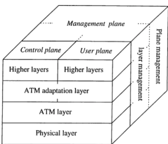
Figure 1.2: ATM protocol reference model (PRM ).
In modern communication systems, a layered ajDi^roach is used for the organization of all cornmuniccition functions. The functions of the layers and the relations of the hxyers with respect to each other are described in a protocol reference model (PRM ) [.56, 57]. Figure 1.2 shows the ATM PRM. It contains three planes: a user plane to transport user information, a control j^lane to maintain the network and perform opera.tional fonctions, and a ma.nagement plane responsible for the management of the diflVirent planes. No la.yered structure is used within the management plane while it is used in the others where three basic layers are defined: the physical layer, the ATM layer, and the ATM :.cition la.yer (AAL). Table 1.1 summarizes the lower three la.yers and their functions.
1.1
The Physical Layer:
The functions of the physical layer and the ATM layer are identical for the control plane and the user plane. Different functions may occur in the ATM adaptation layer as well as in higher layers which are still not well defined. The full descriptions are contained in CCITT Recommendation 1.321 [58] and 1.413 [59].
Chapter 1. Introduction
Layer Sublayer Function
A A L
c s Convergence
SAR Segmentation and reassembly
ATM
Generic flow control
Cell header generation/extrciction Cell VPI/VCI translation
Cell multiplex and demultiplex
PHY
TC
Cell rate decoupling
НЕС header sequence generation/veriflcation Cell delineation
Transmission frame adaptation
Transmission frame generation/recovery
PM Bit timing
Physical medium
Table 1.1: PRM sublayers and functions.
1.2
The A T M Layer:
ATM transfers data in fixed-length units called cells. An ATM cell is 53 bytes long; the first 5 bytes are header information and the remaining 48 contain data. If the payload in a cell is less than 48 bytes, the excessive bytes are fdled by (or padded by) the higher layer. The 48-byte size represents a compromise between the demand of voice trailic tor quick access to the network and the demand of data traffic for large data units. Figure 1.3 shows the layout of the ATM cell. The fields in the header have the following uses:
Chapter 1. Introduction Bit к 7 8 5 4 3 2 I GFC VPI VPI VCI VCI VCI PT RES CLP НЕС
Information field
48 octets
50 51 52 53F igu re 1.3: ATM cell structure.
• G F C Generic Flow Control. 4 bits. Used by the How control mechanism at the user-network interface (UNI). Mechanisms are yet to be determined.
• V P I
Virtucil Path Identifier. 8 bits. Used for directing cells within the ATM network.• V C I Virtual Channel Identifier. 16 bits. Used for directing cells within the ATM network (see discussion below).
• P T I
Payload Type indicator. 3 bits. Identifies the type of data being carried by the cell.• C L P Cell Loss Priority. 1 bit. If this bit is set, the cell has low priority and can be discarded when the network is under stress. If it is not set, the cell hcis higher priority cuid is less likely to be discarded.
• Н Е С Header Error Correction. 8 bits. Generated and inserted by the physical layer. Serves as a checksum for the first 4 bytes of the ATM header. It can correct single-bit errors and detect some multiple-bit errors.
ATM cells flow along entities known as virtual channels (VCs). A VC is identified by its
virtual channel identifier (VCI). All cells in a given VC follow the same route cicross the
network and are delivered in the order they ai’e transmitted. A VC between two users can carry data and signaling information. A VC between a user and the ATM network, on the other hand, can be used for signaling or for administrcitive purposes. Three VCs -numbered 0, 1, and 2- are reserved for special purposes: 0 is for unassigned cells; 1 indicates the rneta-signaling VC; 2 indicates the genercil broadcast signaling VC.
VCs are transported within virtual paths (VPs). A VP is identified by its virtual
path idcntifi,er (VPI). VPs are used for aggregating VCs together or lor providing an
unstructured data pipe. Depending on the requirements of the user and the network, it is possible that not all bits of the VPI and VCI will be significant. Bits tluit are not significcint are set to zero.
The VPI and VCI, taken together form a 24-bit protocol connection identifier (PCI). The PCI identifies a particular call or connection and is used for routing cells across the network iind demultiplexing cells at the destiiicition. Cells with PCI equal to zero are unassigned or unused. They carry no user data.
VPs and VCs are subject to switching within the ATM network. A VP switch can redirect a VP, perhaps reassigning the VPI, but keeps the VCs within the VP intact. A VC switch must terminate VPs and can switch the VCs within a VP independent of each other. All this switching means that the VPI and VCI at different ends of a connection may not be the same. That is, each end point of a connection may refer to the same connection with a different VPI or VCI.
Chcipter 1. Introduction
7
1.3
The A A L Layer:
'I'he ATM adaptation layer enhances the service provided by the ATM layer according to the requirements of specific services. The AAL maps the user’s control or management protocol data units into the information field of the ATM cell and vice versa. The
Chapter 1. Introduction
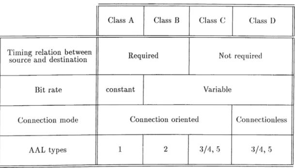
Table 1.2: Classes of traffic and associated AAL layers.
operation of the AAL protocol vary depending upon the type of traffic that is carried. In fact, there are 5 AAL protocol layers defined, each of which is designed to optimally carry one of 4 chisses of traffic as in Table 1.2. This does not imply, however, that only the classes of traffic with which each of the AAL layers are associcited can be supported by a particular AAL. The important distinction here is that between the service offered to the higher layers by the AAL layer, and the type of traffic carried by the AAL protocol across the network. While very often this will be synonymous (e.g. AAL 1 will typically offer Class A service and will carry Class A traffic), this does not always have to be tlie case. In other words, once a connection is established across the ATM network, the network will not care what kind of traffic is carried in the cells, or how that information might be packaged.
AAL 3 was originally meant for connection-oriented variable-bit-rate services without a. required timing relationship; it has been merged with AAL 4. In the following two subsections, we will describe AAL types 3/4 and 5 respectively as they are of interest for con nectionless traffic.
Chapter 1. Introduction
CPI BTag BASize Information Payload Pad AL ETag Length
Figure 1.4: AAL 3/4 CS PDU structure.
ST SN RES SAR-PDU payload LI CRC
j ^ 2 bytes header ^ 44 bytes information bytes trailer
Figure 1.5: AAL 3/4 SAR PDU structure.
1.3.1
A A L 3 /4
AAL 3/4, defined in ITU-TS recommendation 1.363 [60], is defined for services that require
bursty bandwidth such as data transfer. AAL 3/4 actually comprises two sublayers, the
convergence sublayer (CS) and the segmentation and reiissembly (SAR) sublayer. The CS protocol data unit (PDU) structure is shown in Fig. 1.4; the SAR PDU structure is shown in Fig. 1.5. The value of the pad field is binary zeroes. The fields in the CS-PDU are described below.
• Common Port Indicator (CPI): This 1 byte field is used to indicate the usage of the other fields in the CS-PDU, which vary depending upon the modes of operation.
• Beginning Tag (BTag): This 1 byte field is incremented modulo 256 with successive CS-PDUs, and the same value is also placed in the End Tag (ETage). It is used to associate the headers and trailers of a given CS-PDU to ensure that all SAR-PDUs have been received correctly. This detects ATM Layer errors which may cause the misordering of SAR-PDUs and the corruption of CS-PDUs. The AAL layer will check to ensure that the BTag and E lag of CS-PDUs will match, but it will not check the sequence of BTag and ETag values in successive CS-PDUs.
• Buffer Allocation Size Indication (BASize): This 2-byte field is used to indicate to the receiving AAL the maximum size of the buffer required for reassembly of incoming CS-PDU. In message mode, this will be the length of the CS-PDU. In
Cbcipter 1. Introduction
10
streaming mode, it may be some maximum value since the length of SDU being ti'cinsmitted may not be known to the transmitting AAL.
• Information Payload: The maximum size of the infornicition payload is the maximum value of the BASize field (65,535) times whatever the size of the counting unit is, as indicated by the CPI field.
• Pad: The pad field is used to ensure that the total length of the (JS-PDU is a rnultiiDle of 4 bytes, so that transfers at the end-nodes can be facilitated (most computer busses are aligned on 32 bit boundaries). The pad field is never interpreted, so niciy be filled typically with zeros, and its length will vary between 0 and 3 bytes. Note that the Length field in the CS-PDU trailer will indicate exactly how long the payload is, so that the size of the pad can then be calculated.
• Alignment (AL): The 1 byte AL field is used to ensure tlmt the C.S-PDU trailer field is a multiple of 4 bytes, it is set to zero and is not interpreted.
• End Tag (ETag): This 1 byte field is set to the same value as the BTag, ci.s ex]:)lained above.
• Length: This 2-byte field is set to the actual length of the information field, and, a.s explained above, may be less than or equal to the value of the BASize field.
The CS-PDU is passed from the CS sublayer to the SAR sublayer, where it is segmented into one or more SAR-PDU. The fields of the AAL3/4 SAR-PDU are described below.
• Segment Type (ST): This 2-bit field can tcike one of four values. It is used to indicate whether a particular SAR-PDU is carrying the first piece of a CS-PDU (Beginning of Message, BOM ), an intermediate piece (Continuation of Message, COM ), the final piece (End of Message, EOM) or whether the entire CS-PDU is in the single SAR-PDU (Single Segment Message, SSM).
Chcipter 1. Introduction
11
• Sequence Number (SN): This T bit field is incremented for each successive SAR- PDU for a given CS-PDU, and is used to detect the loss or misordering of a SAR- PDU.
• Multiplexing Identification (M ID): This 10-bit field is used to differentiate between multiple CS-PDUs which may be in transit at the same time over the scirne ATM connection. The same MID value must be used on all of the SAR-PDUs of a single CS-PDU. A source will typically cycle through the values of this field to ensure uniqueness, but, as yet, there is no algorithm to ensure global uniqueness over all sources that may be simultaneously transmitting to a given destination.
• Information Payload: The information payload of an AAL 3/4 SAR-PDU is only 44 bytes long, and contains the segmented pieces of a CS-PDU.
• Length Indicator (LI): The 6-bit length indicator is used to indicate how many of the 44 bytes of payload actually contain user data (i.e. apiece of a CS-PDU). An EOM or SSM SAR-PDU may not contain 44 bytes of data. The value of the LI must be a multiple of 4 bytes.
• Cyclic Redundancy Check Code (CRC): The 10-bit CRC covers the entire SAR-PDU and is used to detect bit errors.
Note that the operation of AAL 3/4 is by no means trivial, it is based, for the most part, on the IEEE 802.6 DQDB protocol, which itself is fairly complex. Furthermore, many aspects of its operation have yet to be fully specified. This is of great concern since, as noted. Class C operation is likely to be the most important mode of operation for ATM networks, cit least in the short term [27].
1.3.2
A A L 5
AAL 5, the Simple and Efficient Adaptation Layer (SEAL) [61], attempts to reduce the complexity and overhead of AAL 3/4. It eliminates most of the protocol overhead of
Chapter 1. Introduction 12
0-65535 bytes ^ 0-47 bytes^ j ^ 7 bytej^
Informayion Payload Pad Trailer
Control Length CRC
1 bytes 2 bytes 4 bytes
Figure 1.6; AAL 5 PDU structure.
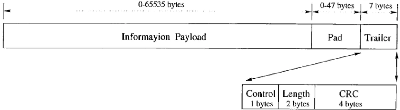
AAL 3/4. Like AAL 3/4, AAL 5 comprises a convergence subla.yer and a SAR subla.yer, cilthough the AAL 5 SAR sublayer is es.sentially null. The structure of the AAL 5 CS PDU is shown in Fig. 1.6.
The fields of the AAL 5 CS-PDU are described below.
• Information Payload: The AAL 5 information payload can vary from 0 to 65,535 bytes.
• Pad: The pad field in the CS-PDU ensures that the total length of the CS-PDU (including pad and trailer) is divisible by 48 and that the CS-PDU trailer resides in the la.st eight bytes of the last 48-byte chunk. This is required since there is no length indication in the SAR-PDU. The value of the pad held is binary zeroes and its length can vary between 0 and 47 bytes.
• Control: This 1-byte field is reserved to support future AAL functions; at present, it is coded all zeros.
• Length: The 2-byte length held indicates the length of the information pa.yload.
• Cyclic Redundancy Code-32: This 4-byte held contains a 32 bit CRC calculated over the CS-PDU, and is used to detect bit errors.
When a. network node has a datagram to transmit, it first converts it to a CS-PDU l)y adding the pad, if necessary, and trailer. Then it breaks the CS-PDU into 48-byte
Chapter 1. Introduction
Figure 1.7: Bearer services and teleservices.
SAR-PDUs and transmits each in an ATM cell on the same virtual channel. The last SAR-PDU is rricirked so that the receiver can recognize it. Since there is no AAL 5 SAR header, an end-of-frame indication in the ATM cell header is required. The proposed end-of-frcime indication is an SDU type of 1 (binary value ‘ 0X1’) in the Paylocid Type indicator (PTI) field.
The receiver simply concatenates cells as they are received, watching for the end-of- frame indication. When it is received, the receiver checks its length, the CRC, and passes the PDU up to the next higher layer. The higher layer is responsible lor ignoring PDUs with CRC errors. Some applications may discard PDUs with errors; others (e.g. voice or video, which can tolerate some errors) may choose to use them, or to do error correction.
1.4
Bearer Services and Teleservices
Services are categorized based upon their scope cind the source of the service a.s shown in Fig. 1.7. Dearer services cire offered by the ATM layer and involve lower layer functions. They act as simple carriers, carrying information unchanged from end to end. Teleservices are value-added services offered by higher layers, above and beyond the mere transport of bits.
Bearer services are offered, in a connection-oriented transfer mode, as a. point-to- point virtual connections each identified by a certain V CI/V PI. A virtual connection is chara.cterized by its capacity (bandwidth) as well as the quality of service ((JoS) that
Clmpter 1. Introduction
14
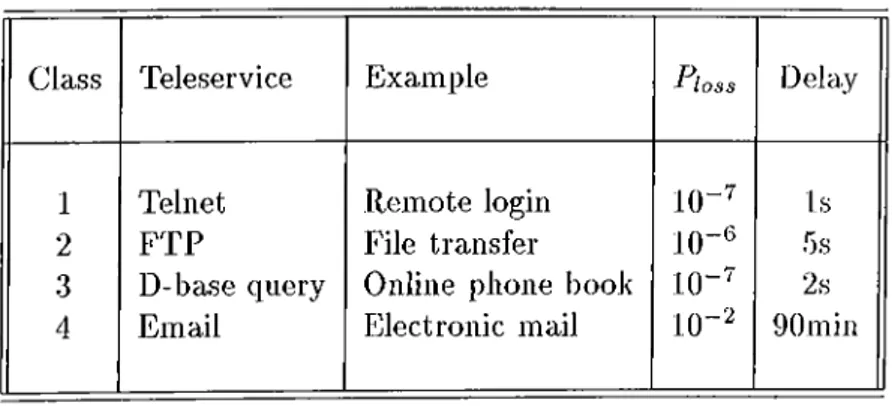
Class Teleservice Example loss Delay
1 Telnet Remote login 10-^ Is
2 FTP File transfer 1()-^ 5s
3 D-base query Online phone book 10-^ 2s
4 Email Electronic mail 10“ '^ 90min
Table 1.3: Teleservices classes and examples.
insures. The bandwidth (BW ) is function of the traffic statistics while the QoS may be characterized by the delay, delay jitter, and the cell loss probability.
Teleservices are often offered in connectionless transfer mode. They are designed to match the various user appliccitions. Applications are categorized according to delay and loss sensitivities as well as the associated traffic pattern. Widely used applications in LAN and MAN environments are summarized in Table 1.3.
Chapter 2
Provision of Connectionless Service
If connectionless service is to be provided in an efficient and effective manner in public ATM environments, a number of issues must be dealt with. These issues include: where to loccite connectionless servers, how to interconnect them, how to manage bcindwidth, how to forward packets, and how to resolve destination addresses.
2.1
Internetworking Methods
A number of methods have been studied and proposed for internetworking connectionless entities over a connection-oriented ATM network [7-37]. In this section we shall describe the important ones and discuss their merits.
2.1.1
The Direct Methods
An early approach to ATM connectionless support is mentioned in [10]. Basically, each cell carries the full destiricition address. The wastage of cell pciyload due to the full destination address is the major drawback of this method. Variants to this method [11, 12, 13] are sed on the observation that the number of addressable entities is considerably smaller
Chcipter 2. Provision of Connectionless Service
16
Switch 1 r Host UNI r ---1() vpi="d.·· ) [ ^ X Q
Switch N VPC between 1 and N @ = l .X VCl=N.y fDetermine VPC^ to Switch NJ
VCI=x.y I--- 1 UNIP | X [p () vpfa‘cis''i)
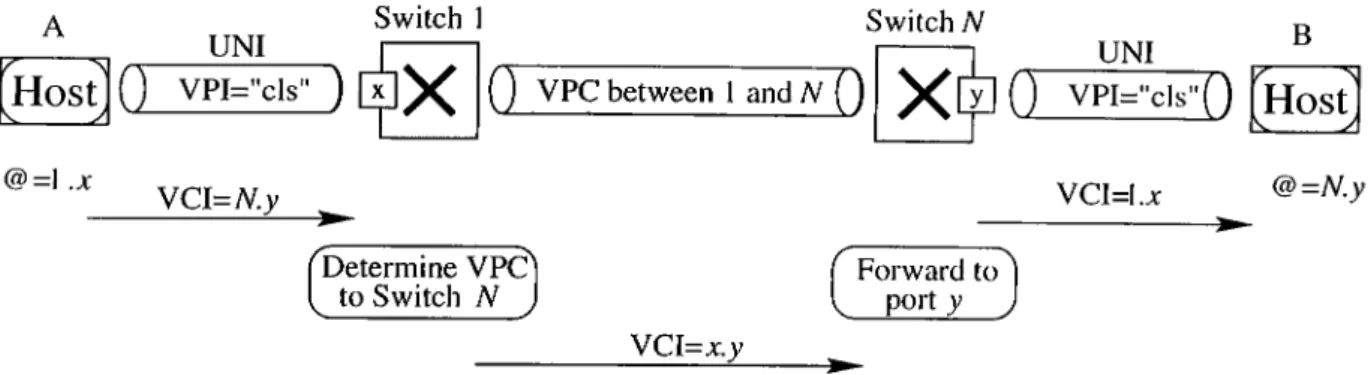
B Host VCI=I.a: @=N.y Forward port rd to^ I __ )Figure 2.1: Direct ATM connectionless data service.
in a local network than in public network. Therefore, it is possible to use very short addresses to identify the various equipment, and to carry such addresses in the V P I/V C I field of the ATM cell header.
The basic principles of the method are shown in Fig. 2.1. At the user-network interlace (UNI) a virtual path connection, identified by the VPI value ‘ els,’ is dedicated to the connectionless traffic. Furthermore, every station piirticipating in the connectionless service is assigned a two-byte short address @. Every cell to be sent to a certain destination carries in its VCT field the short address of that destination. To simplify the routing functions in the switches, the short addresses are structured into two subfields: switch identificcition (SI, 1 byte) and port identification (PI, 1 byte). Thus the short address assigned to ci station identifies its loccition in the network, or more precisely its network attachment point. In the example of Fig. 2.1, station A on the left is assigned the short address CS=l.a: because it is attached to Port x of Switch 1. Simihudy, station B on the right is assigned the short address @=N,?/ because it is attached to Port y of Switch N. All cells that station A sends to station B carry in their VCI field the short address of B, namely N.y.
Within the network, any pair of switches is interconnected by means of a VP connection. These inter-switch VPs are exclusively reserved tor the excluinge of connectionless traffic between the two switches. As the short address is structured in St and PI, a source switch can forwiird the cells either directly to one of its access ports (if SI matches with its own identification), or to the destination switch over the appropriate
Chciptev 2. Provision of Connectionless Service 17
VP. On the inter-switch VPs, the VCI field carries the identification Pis of both source and destination ports. At the destination switch, the cells are forwarded further to the destination jDort, but with the VCI field now containing the short address of the source station. In Fig. 2.1 the cells sent by Switch 1 to Switch N contain in their VCI field the Pis of both stations A cind B, namely VCI = x.y. Then the cells sent by Switch N to stcition B contain the short address l.x of the source station A. The destination switch has derived the source SI from the identification of the VPC over which the cells were received, cind the source PI was carried in the VCI field of the cells together with the destination PI. In this way, the destination can learn the short address of the source.
Because the cells sent to the destination station contain in their VCI field the short address of the source station, messages coming from different sources can l^e sent cell- interleaved to the destination over the access VP (with VPI = els). Thus an MID field is not needed for message reassembly and AAL 5 can be used. The only restriction is that a source cannot sent multiple messages in parallel to the scirne destiucition. That restriction is however aeceptable for most applications.
A special PI-value, e.g., all ones, is reserved for broadcast traffic. Cells sent with this PI-value are forwarded by the source switch to all switch BPs, on which the VCT field carries again the Pis of both source and destination ports. Finally, cells containing broadcast traffic are sent to the destinations with the VCI field containing the short addr ess of the source station.
The most attriictive feature of this method is that it offers a “network” connectionless service, that is a connectionless service at the user-network interface and not a high levod service. Indeed, it does not require the support of signaling control for setting up and releasing connections. It allows the transfer of the connectionless traffic directly in the ATM layer (hence the name “direct method” ). The switches forward the cells based solely on the values contained in their V P I/V C I field, as they also do for connection-oriented traffic. They do not have to analyze the information contained in the messages.
Chapter 2. Provision of Connectionless Service
18
V P I/V C I values. It requires the implementation of a special routing table in the ATM switches, and therefore cannot be supported by standard ATM switches. Also the two- byte short addresses and their structuring into switch and port identification constitute an architectural size limitation.
2.1.2
Connection-based Methods
With connection-based methods, a virtual channel connection must be established between every pciir of communication stations. In order to send a message to a certciin destination, a source station must check whether it has a connection to that destination. If so, the message is transmitted over the available connection. Otherwise, it must establish the connection first, and then transmit the message.
The most attractive feature of the connection-based method is its direct cuid efficient use of the ATM switching capability. It is also transparent to the ATM switches, i.e., it does not i^ut any specific requirements on the switches. But because of this efficient use of the ATM connections, one could argue whether it really provides an ATM connectionless service. From an ATM network standpoint, it clearly does not, because the ATM switches still ¡provide connection-oriented services only. The connectionless service itself is provided b^^ a. convergence function within the end stations. This convergence function receives connectionless messages from the higher layers and transmits them to their destination over the appropriate ATM connections. On one side, it hides its higher layer users from ail connection-oriented aspects of ATM and the related complexity, like signaling control a.nd connection management. On the other side, it hides the ATM network from tlie connectionless characteristics of the interface it provides to the higher layer users. From the standpoint of LAN emulation, however, it meets exactly its objective of providing a MAC connectionless interface.
If we were seeking a true network connectionless service, then the Partial Connection method described in [14] and [15] would be an attractive alternative. With this method, there are also ATM connections between the two communicating stations, but the end
Clmpter 2. Provision of Connectionless Service
19
stations are not aware of these connections and cire relieved from any siginding and connection management functions. Within the network a “Connectionless Access Agent” takes care of setting up connections when needed and releasing them when they are no longer required.
The following arguments have been raised against using the connection-based method. 'The xnajor issue is the overhead of sigiiciling control lor setting up and relecising connections. This signaling overhead is twofold: first the method would require stations to imiDlement the signaling and connection management functions (not required by the Partial Connection method described above), and secondly it would creci.te too much control traffic on the network. The delay caused by the connection setup phase is cdso a concern. Furthermore, the method is inefficient because not only a large number of connections would be required to interconnect all communiccition stafions, but network resources must also be reserved even when the connections are not used due to the l)Lirstiness of the data traffic. We shall now examine the validity of these arguments.
A close look at the ATM stations will reveal that they must in general implement the functions needed for setting up and releasing connections, because the driving force of ATM is its native support of multimedia services by means of connection with guaranteed qucility of service. Thus all ATM stations will ultimately support switched connections, and this functioiicility can also be used to set up connections needed by the LAN emulation service.
The load on the network due to the control traffic for connection setup and release could be minimized if the connections are established not only for the transfer of a single issage, but for the entire duration of the communication (which usually consists of the xchange of multiple messages). Also the impact of the connection setup delay will be reduced, beccuise it applies to the first message only, and not to the following ones. In the majority of focal networks, this delay is usually small because of the small number (e.g., two or three) of switches involved in a connection.
'riie concern about wasting network resources may be valid in a WAN environment. me
Chapter 2. Provision o f Connectionless Service
(a) Integrated approach
20
(b) Stand-alone approach
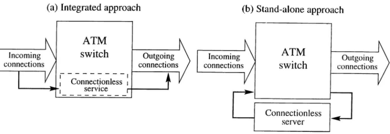
Figure 2.2: Stand-alone and integrated connectioidess seI'vers.
but certainly not in a LAN context, where the best-effort or cwailable bit rate (ABR) service is a requirement [16]. A best-effort connection only consumes network bandwidth and buffer space if it is currently carrying traffic. During idle periods, it does not occupy any network resource except the entries of the V P I/V C I mapping tables. If necessary, the large number of connections could also be reduced if stations would only maintain active connections, while those connections with long idle periods would be relecised by mecins of some cictivity monitoring. Moreover, there are some techniques proposed in the literature to maiicige the network bandwidth allocated to these connections (see Section 2.2).
2.1.3
Server-based Methods
The previous two approaches integrate the connectionless service function into the ATM switch as modeled in Fig. 2.2ci. On the other hand, the approach addressed in this subsection cippend a connectionless server unit externally to the ATM switch (Fig. 2.2b), therefore, it iriciy be referred to as the stand alone approach.
The stand alone approach rely on an additional network of packet switches (i.e., non-ATM switches), usually called connectionless servers (CLSs) [17, 18]. Every station participating in the connectionless service has a connection to ¿it least one connectionless server, and there are connections between the servers as well. The connections to and among the servers rruiy be switched or permanent. To transfer a message using the
Chcipter 2. Provision of Connectionless Service
21
O U T IN
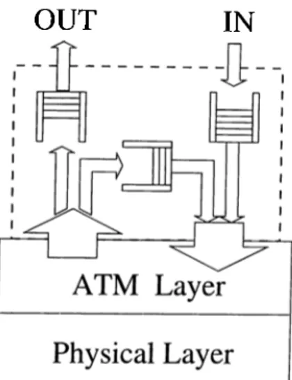
Figure 2.3: A CLS on top of an ATM node.
connectionless service, a source station appends the destination address (cuid eventually the source address as well) to the message and simply forwards it to the connectionless server to which it is attached. Upon receiving the message the connectionless server analyzes the destination address of the message to determine the outgoing ATM connection on which the message has to be forwarded. There are two possible methods for forwarding messciges: cell based forwarding, and frame based forwarding. I'liese methods will be described in Section 2.3. Fig 2.3 illustrates the basic structure of the connectionless server.
The server-based concept described above builds for example on the l)ci.se of the “ B- ISDN Connectionless Data Service” [9], defined by ITU-TS for public ATM networks, and the Switched Multimegabit Data Service (SMDS).
The most aj^pealing feature of the server-based architecture is its simplicity for the end stations. To transfer a connectionless message, a station simply gives it to the servers, which will then take care of forwarding it to the target. No routing decision has to be made by the stations. Furthermore, a close look at the functions to be performed by the servers reveals that they are similar to those performed by toda.y’s ¡'outers and Irridges, namely mapping destination addresses (which could be MAC, IP, E.164, or any other addresses) to outgoing ports.
Chapter 2. Provision of Connectionless Service 22
Another advantage of the method is that it does not put any specific requirements on the ATM switches. Connectionless switching is performed by the servers, which can be developed independently, and their services can be accessed by means of standard ATM connections. Thus any connectionless protocol needed between stations and servers cuid among servers themselves are transparent to the ATM switches. This transparency makes the server method attractive to public networks, because it allows a clear technical and cidministrative separation between the basic connection-oriented service of an ATM public network and the value-added connectionless service.
The server-based method has a weakness concerning throughput performance, which could be avoided by integrating the connectionless server functions into the switches. This integration, however, is not ti'cinsparent and therefore could not be supported by stanchird ATM switches. The same issue regarding transparency to the switches applies to the direct method. The connection-based method, on the other hcind, places no specific requirement on the ATM switches (the transparency feature).
It is not likely that connectionless servers will be placed at every switch in the ATM network. Therefore, the determination of where to phice them and how to interconnect them has important performance consequences. One recommendation is to phice connectionless servers cit each interworking unit’s first-hop switch [30]. This configuration eliminates switch-to switch connections between an interworking unit and the first-hop connectionless server, improving the bandwidth efficiency and subscriber cost of first-hop connections. It also makes management of connectionless service simpler, since address screening and tariff calculation will most likely occur at the local switch. However, placing connectionless servers more centrally may reduce the number of servers required.
In ciddition to the location of connectionless servers, their interconnection also deter mines the performance and flexibility of the offered connectionless service. The topology of a virtual connectionless network ultimately determines how quickly connectionless cells are routed from source to destination. Due to the connection-oriented nature of ATM, virtually any topology for the interconnection of connectionless servers is possible.
Chcipter 2. Provision of Connectionless Service
23
(a) Complete mesh
Ù
- t ·
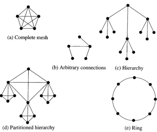
Figure 2.4: Connectionless server network topologies.
However, five basic topologies have been proposed as feasible alternatives: complete mesh, arbitrary connections, hierarchical tree topology, and ring topology [69, 70]. Figure 2.4 illustrates each of these alternatives.
I ’lie complete mesh is perhaps the most intuitive topology and entails the connection of each connectionless server to every other server. Бог relatively smaller public networks, this method may prevail since the number of servers required is small and end-to-end delay is minimal. Ilowever, for public wide area ATM offerings, the mesh is problematic for the same reason that the indirect approach is problematic. If n is the number of connectionless servers in the network, O(n^) connections, each of which may use a non-negligible amount of network bandwidth, become necessary to complete the mesh.
The arbitrary interconnection of connectionless servers reduces the numljer of con nections between servers required to support connectionless service. Each connectionless server is connected arbitrarily to one or more other connectionless servers in the network, and routing tables in each server are updated to reflect their interconnections. This
Chcipter 2. Provision of Connectionless Service
24
topology has the advantage that the routing tables in each server are smaller than those lor the mesh.
An alternative to the rather intuitive server interconnection schemes presented above is to connect connectionless servers hierarchically into a tree topology. Figure 2.4c illustrates such a virtual connectionless network. This topology may l)e useful for hierarchical addressing schemes like E.164. For instance, each level of the tree may perform its routing operation on a different chunk of the destination E.164 address. The problem with the strict hierarchical topology, however, is that servers near the root of the tree may become congested as communication across sub-trees increases.
One way to alleviate this congestion is to organize connectionless servers into a partitioned hiercirchical tree topology as shown in Fig. 2.4d. Ecich level of the hiei’circhy is partitioned into several groups of servers, each of which is capable of communicating directly with any other server in its group. If the number of servers in a partition is kept low, routing tables remain relatively small. This scheme hcis the advcintage that it reduces congestion through parent servers. The size of the routing table is slightly larger tlum it is in the case of non-partitioned hierarchy, but only by an amount proportional to size of the partition mesh.
Also possible for the interconnection of connectionless servers is the ring topology as shown in Fig. 2.4e. One of the primary benefits of the ring topology is that it reduces the complexity of routing algorithms otherwise required by mesh topologies. Cells are merely forwarded along fixed routes between connectionless servers and copied to destination interworking units when appropriate. Another advantage of a ring topology is that it sirnplihes broadcast and multicast transmission of connectionless data. Since data circuhites on a closed ring of connectionless servers, it can be copied and sent to any riurnber of interworking units in the network. However, one of the problems associated with this topology is that the ring may grow substantially in larger networks,, resulting in transmission and processing delays.
Chcipter 2. Provision of Connectionless Service
25
2.2
Bandwidth Management
'Phe problem of bandwidth allocation for the virtual connections used for connectionless trafiic has been addressed extensively in the literature. The allocation of peak l)andwidth is conservative and causes unacceptable wastage of the network capacity. Dynamic bandwidth renegotiation [19-22], fast reservation protocol [23, 24], and on-the-fly transmission [25, 26] are solutions proposed in the literature.
2.2.1
Dynamic Bandwidth Renegotiation
This scheme assumes that a small amount of bandwidth is initially allocated to the virtual connections. The allocated bandwidth is increased when the instantaneous traffic exceeds the limit, and decreased when the traffic subsides. In other words, if a burst exceeding the peak rate arrives at the internetworking unit (INU), it progressively fills the buffer. When the queue exceeds a given threshold (T2), bandwidth is renegotiated to increment the current cdlocation. Likewise, bandwidth is decremented a.s the queue size goes below a specified threshold (T l) which is smaller than T2 as shown in Fig. 2.5. The goal of this approach is to absorb a traffic burst in the INU buffer as much as is prcictically feasible (because of buffer size and delay), and to resort to renegotiation only when the burst is of sustained length. The problem is that to avoid bandwidth fragmentation and wastage, only a very small amount of bandwidth can be allocated to each virtual connection in idle conditions. Thus each new burst pra<:tically triggers a renegotiation which has a cost appears in a. delay (in the order of 70 ms) and a stress on the ATM network. Also this scheme suffers from the very large buffers required in the INUs.
2.2.2
Fast Reservation Protocol
In this scheme the virtual circuit is established when the connection is set up. 'I'tie l)andwidth, however, is allocated only when an activity period begin (i.c., a burst arrives). Namely, the source indicates the peak bit rate in a reservation message which is sent
Chciptev 2. Provision of Connectionless Service
26
T2
T1
Figure 2.5: Dyiuimic bandwidth renegotiation.
down the path. Switching elements along the path allocate the (peak) bandwidth . If bcindwidth is available all cdong the path a Positive Acknowledgment is returned, and the burst can be transmitted. Otherwise, a Negative Acknowledgment is returned, and the source is blocked and must retry later. The claim in [23] and [24] is that the Fast Reservation Protocol is fully hardware implementable cuid can be performed in one cell time per stage.
2.2.3
On-the-fly Transmission
'Phis scheme allows bursts to enter the ATM network on-the-fly (rather than filling the entry buffers) as long as there is enough free bandwidth on the ])a.th. A l)a.ndwidth advertising procedure is defined to report residual bandwidth information to the INUs. Abusive cells (i.e. cells exceeding the peak rate allocated to the VP) have a. good chance to get through because of the knowledge of the amount of residual bandwidth at the INU and the very conservative (¡Deak bandwidth) allocation policy generally used for VPs carrying connection-oriented traffic. As traffic builds rpi on a VP, more bandwidth will be requested by the INUs based on long-term traffic measurements on that VP. Likewise, bandwidth is deallocated when traffic subsides. Thus this scheme tries to track user requirements by dynamic VP bandwidth management like the renegotiation scheme did. Here, however, the traffic surge is not buffered in the INU waiting for more bandwidth to be alloccited rather it is allowed to overflow into the network at a rate compatible with the residual bandwidth advertised by the network. If the overflow condition persists beyond a given critical time (chosen to be at least one order of magnitude larger than tlie
Chapter 2. Provision of Connectionless Service 27
bandwidth renegotiation time) the INU can request an increment of bcuidwidth cidequate to accommodate the extra traffic observed during the overflow period. Thus a second difference with respect to the previous scheme is that bandwidth renegotiation is not triggered by queue length rather than by measured traffic rate. Furthermore, the INU knows in advance how much bandwidth is available on the path (bcca.use of ba.ndwidth advertising). Therefore, it can request the full bandwidth amount (provided that it is within the available limit) needed to satisfy the trciffic increase rather thcin stepping through a series of small increments. The bandwidth advertising ineclmnisms that is assumed to exist in the ATM network feeds the INUs with up-to-date inibrmation on available bcindwidth on their outgoing VPs (i.e. the minimum bandwidth which is not allocated in all trunks of the VPs) The bandwidth information must be timely and efficiently dispatched to the INUs to assist them in the handling of connectionless traffic.
The advcintages of the proposed bandwidth advertising policy are shorter queues and lower delays cilong with improved efficiency. The drawbacks appear in the bandwidth cidvertising overhead and the marking bit cost.
2.3
Forwarding Schemes
The servei’-based approach requires each CLS to make routing decisions and forward frames. There are two possible methods for forwarding frames: cell based forwarding, and frame based forwarding [18]. In connectionless servers based on cell based forwarding, incoming cells are transported in a streaming mode, where the arrival of the first cell of a frame creates an internal mapping from the incoming connection identifier (V P I/V C I) and frame identifiers (MID) to the appropriate outgoing connection and frame identifiers. All successive cells of the same frame then are forwarded bcised on the mapping created l^y the first cell in a stream without the need for frame rea.ssembly. Servers tha,t operate in this rncinner are referred to as streaming mode connectionless servers.
Chapter 2. Provision of Connectionless Service
28
the address of the next CLS is determined for the frame, and the frame is resegmented into cells that are delivered to the next CLS via the ap2Dropriate connection and frame identifiers. Connectionless servers that operate in this mode are referred to as reassernhly
mode connectionless servers.
For reassembly mode CLSs there are three options available lor transmission of multiple frames: frame, cell, or hybrid interleaving. In frame interleaving, all frames are transmitted contiguously. Only after the complete transmission of a frame can other frames be transmitted, in cell interleaving, the transmission of cells from multii^le Ifames are interleaved as the frames are ready for transmission. Streaming mode trcinsmissions are inherently cell interleaved. In hybrid interleaving separate Irame interleaved ti’cinsmission queues are maintained for each out going connection. The frames from each of these queues cire then cell interleaved for subsequent transmission on the physical medium. Tins hcis the effect of frame interleaving with resi^ect to a VC but cell interleaving with respect to the ATM switching fabric.
The use of cell or hybrid interleaving reduces cell loss at the ATM switch by decreasing the burstiness of cells destined for the same output port. However, due to the consecutive cell loss nature of ATM, frame interleaving will isolate cell loss periods to fewer frames, reducing the overall frame loss rate. Using frame interleciving, only a small number of frames may be affected during a loss period. Using cell or hybrid interleaving, many frcunes may be affected by a lossy period. Thus, for the same cell loss i-ate, cell or hybrid interleaving rmiy show a higher frame loss rate than frame interleaving.
The use of reassembly mode CLSs may introduce targe delays relative to that exy^erienced with streaming mode CLSs. This additional delay is the result of recei^tion delay, queuing delay, and jDrocessing delay. Since this delay is experienced at each CLS hop, routes with a greater number of hops will experience proportioncilly longer delays.
Reassembly mode CLSs must maintain buffer sj^ace lor the reassembly ol iraníes. Depending on the buffer management scheme, this limits the number of frames tliat can be in transit and possibly the maximum frame size. The buffer management scheme
Chapter 2. Provision of Connectionless Service
29
can either use variable sized or fixed sized bufFers. The use of variable sized buffers requires more sophisticated management schemes to find a buffer that the “ best fit” for a given frame. Additionally, the use of variable sized buffers can result in inelhcient buffer utilization due to fragmentation caused by “islands” of allocated buffers that split free regions of buffer space into multiple, smaller regions.
2.4
Address Resolution
One other issue complicating the provision of connectionless service for wide area ATM networks is address resolution. Suppose host a in LAN A wishes to trimsmit connectionless data through the wide area ATM network to host b in LAN B. Assume the interworking unit connecting LAN A to the ATM network knows that host h resides in LAN B. Communication should then take place according to the route { « , ... ,IWU^,...,IW U s,...,6}, where IWUx is the interworking unit connecting LAN X to the ATM network. In this simple example, complex address resolution is not required since LAN A is aware of host 6’s location. However, in most cases, interworking units are not initially aware of the LAN in which cinother host resides. Addi'ess resolution must therelbre take place in order to discover the address of the destination interworking unit so that communication with the destination host can occur.
There are essentially two classes of address resolution techniques that an interworking unit may utilize in order to discover a destination interworking unit address. One technique consists of broadcasting the destination host a.ddress to each interworking unit in the ATM network cind waiting for the appropricite interworking unit to respond with its ATM address. This technique is similar to the Address Resolution Protocol (A R P ) [72, 73] commonly used in LANs and requires the existence of ATM multicast service. The other technique consists of querying centralized or lightly distributed ciddress resolution databases, each of which is updated with a list of host addresses whenever a new interworking unit is added to the network. This is the approach that IETF IP over ATM working group has adopted.
Chapter 2. Provision of Connectionless Service
30
Although ARP was originally intended for use in networks using sluired media, it can be extended to ATM networks if they have broadcast or multicast capability. One possible approcich to using multicast ARP for ATM connectionless service is to model it after the multi-LAN address resolution technique. When an interworking unit wishes to transmit a. (X)nnectionless frame to a host in a LAN connected to the network at some unknown location, it broadcasts an address resolution request to every other interworking unit in the ATM network. As interworking units receive the request, they compare the requested destination addresses. If found, and the destination host exists in the interworking unit returns its own ATM ciddress to the source of the ARP request so that it may serve as a proxy for the destination host. If the address is not found in the Cciche, the interworking unit performs a local ARP request on each of its connected LANs and determines if the specified host is connected.
An alternative to multicast ARP is to use address resolution entities or ARP servers [16]. these ARP servers are placed in the ATM network and respond to address resolution requests from interworking units. Whenever an interworking unit joins the ATM network, it updates the nearest ARP server with a list of host addresses in its attached LAN(s). Address resolution proceeds by querying ARP servers with a. host address and receiving the destination interworking unit address in return. As in the case of the multicast address resolution protocol, interworking units serve as proxies for host data. Note that the functionality of this type of address resolution requites that each interworking unit know at least one ARP server’s address.
For even larger interconnected environments, where networks are interconnected to networks that are in turn interconnected to other networks, simihir server-based solutions have lieen proposed for address resolution. This has been the primary area of work lor the lE T F ’s Routing Over Large Clouds Working Group [71].
There are tradeoffs involved with these two address resolution techniques. The multicast ARP method requires the broadcast of ARP packets to a. large lumiber ol interworking units. This broadcasting may not be feasible in wide area. ATM networks where network resources are scarce. Although interworking units can reduce theii need to
Chapter 2. Provision of Connectionless Service
31
broadcast ARP requests by locally caching the results of previous requests, the broadcast of address resolution packets to a large set of interworking units of which only one contains the actual destination host is inefficient to say the least. The ARP server technique reduces the amount of traEic necessary to perform address resolution but trcinsfers complexity and storage requirements to one or more central servers. It is also much less fault tolerant than the multicast ARP method. If a single ARP server crashes, its entire dafal)ase may become uiicivailable unless there are multiple ARP servers.