2. B. Subbarao, V. Srinivasan, V.F. Fusco, and R. Cahill, Element suit-ability for circularly polarized phase agile reflectarray applications, Proc IEE Microwaves Antennas Propag 151 (2004), 287–292.
3. J.A. Encinar and J.A. Zornoza, Three-layer printed reflectarrays for contoured beam space applications, IEEE Trans Antennas Propag 52 (2004), 1138 –1148.
4. Y. Dunbao, G. Qiang, W. Chao, Z. Chang, and Y. Naichang, A novel polarization convert surface based on artificial magnetic conductor, in Proceedings of the Asia-Pacific Microwave Conference, APMC’05, 2005, Vol. 3, pp. 1, 2.
5. K. Karkkainen and M. Stuchly, Frequency selective surface as a polari-sation transformer, Proc IEE Microwaves Antennas Propag 149 (2002), 248 –252.
6. P.J. Ferrer, Study and numerical simulation of EBG surfaces and broadband antennas arrays, M.S. Dissertation, Universite´ Catholique de Louvain, 2005.
7. X. Dardenne and C. Craeye, Analysis of infinite and finite broadband low-profile arrays, In Proceedings of the 26th ESA Antenna Technology Workshop on Satellite Antenna Modelling and Design Tools, Noord-wijk, November 2003, pp. 167–174.
8. C. Craeye and F. Capolino, Accelerated computation of the free space Green’s function of semi-infinite phased arrays of dipoles, IEEE Trans Antennas Propag 54 (2006), 1037–1040.
© 2006 Wiley Periodicals, Inc.
DESIGNING MATERIALS WITH DESIRED
ELECTROMAGNETIC PROPERTIES
Irfan Bulu,1,2Humeyra Caglayan,1,2and Ekmel Ozbay1,2,3
1Nanotechnology Research Center
Bilkent University Bilkent Ankara 06800, Turkey 2Department of Physics Bilkent University Bilkent Ankara 06800, Turkey
3Department of Electrical and Electronics Engineering
Bilkent University Bilkent
Ankara 06800, Turkey
Received 15 June 2006
ABSTRACT: In this work, we suggest and demonstrate a robust
method to tune the plasma frequencies of wire mediums. The method we suggest involves the use of two or more wire arrangements in the unit cell. By incorporating the method we suggested it is possible to tune the plasma frequencies of wire mediums effectively by use of lower metal densities. In addition, we study the effective permittivities and perme-abilities of labyrinth based metamaterials. Our results show that the effective permeability of the labyrinth based metamaterial medium is negative above a certain frequency. The results of the effective permit-tivity calculations for the labyrinth based metamaterial medium reveal that the labyrinth structure exhibits a strong dielectric response near the magnetic resonance frequency. Finally, we design labyrinth based left-handed mediums that have several desired properties such as simulta-neous, ⫽ ⫺1 and , ⫽ 0. © 2006 Wiley Periodicals, Inc.
Microwave Opt Technol Lett 48: 2611–2615, 2006; Published online in Wiley InterScience (www.interscience.wiley.com). DOI 10.1002/mop. 21988
Key words: metamaterials; split ring; effective medium; negative index 1. INTRODUCTION
Metamaterials recently attracted great interest from the scientific community [1– 8]. One of the major reasons behind this enormous
interest is the possibility of engineering materials with desired properties in their response to electromagnetic waves. The re-sponse of a material to electromagnetic waves is described with its permeability and permittivity [9]. The spectrum of the values of permittivities of naturally occurring materials includes negative and positive values. On the other hand, the permeabilities of naturally occurring materials are known to be positive. The lack of materials with negative permeabilities restricts one’s freedom in designing materials with the desired properties. This issue was addressed by Pendry et al. [2]. Pendry suggested several structures that posses negative permeabilities over a certain frequency range [2]. Soon after, these structures were experimentally realized to exhibit negative permeabilities [3– 8]. The major idea behind all of these structures is to create a magnetic dipole that has some “inertia” by means of an RLC circuit. The “inertia” is introduced through the capacitance. The resemblance between the harmonic oscillator equation and the current-voltage equation for an RLC circuit is rather remarkable in this sense. The capacitance term in the RLC current-voltage equation is the equivalent of the mass term in the harmonic oscillator equation. Due to the finite “inertia”, the magnetic dipole oscillates completely out of phase within a certain frequency range with respect to the incident magnetic field. A regular collection of such magnetic dipoles lead to the realiza-tion of negative effective permeabilities. Materials that possess negative permeabilities open the door for diverse possibilities of physically interesting phenomenon and novel applications such as negative refraction [3–7], subwavelength focusing of light [10 – 12], reverse Doppler shift [13, 14], and lenses with resolutions well beyond the conventional lenses [15].
One most commonly used structure to achieve negative perme-ability is the split-ring resonator (SRR) [16 –22]. SRR structure has several undesired properties. Two of these undesired properties are electric coupling and bianisotropy [22–24]. Recently, we proposed a modified split-ring resonator structure, labyrinth structure, to overcome these two problems associated with the SRR structure [25]. We experimentally and theoretically showed that the laby-rinth structure posses negative permeability over a certain fre-quency range. We also showed that the labyrinth structure is not bianisotropic. In addition, we demonstrated that when combined with a periodic arrangement of wires, the labyrinth medium ex-hibits left-handed transmission. We were able to demonstrate the subwavelength focusing of light by use of a labyrinth based left-handed medium [11].
In this study, we theoretically studied the effective medium parameters of a labyrinth based left-handed medium by means of a retrieval procedure [26 –32]. We showed that one can tune the properties of the labyrinth based left-handed medium by using various arrangements of wires in the unit cell. In addition, we proposed and theoretically demonstrated two labyrinth based left-handed mediums that posses simultaneous, ⫽ ⫺1 and , ⫽ 0. It was suggested that a slab of material that has, ⫽ ⫺1 may focus the light beyond the diffraction limit [15]. On the other hand, a medium with, ⫽ 0 may be used to realize certain potential applications such as delay lines with no phase differences between their inputs and outputs, and beam shaping [33].
2. TUNING THE PLASMA FREQUENCY OF THE WIRE MEDIUM BY USING DIFFERENT ARRANGEMENTS OF WIRES IN THE UNIT CELL
The labyrinth structure consists of four rings. There are two cuts on each ring and the rings are rotated 90° with respect to the adjacent ring. The details of the structure can be found elsewhere [25]. The labyrinth structures are on the front side of FR-4 printed circuit boards and the wires are on the back side. We considered the various
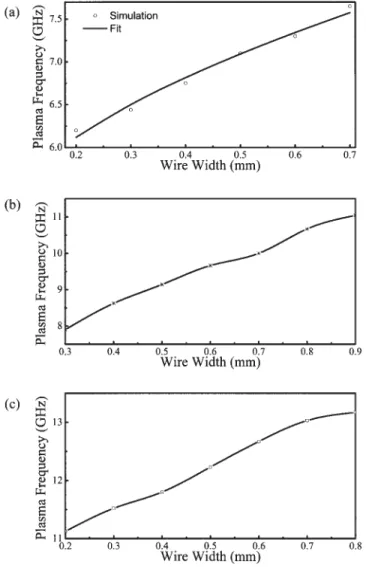
arrangements of wires in this study. These arrangements included one wire, two wires, and three wires in the unit cell. It is well-known that a periodic arrangement of wires has negative permittivity below a certain frequency, namely plasma frequency. We calculated the plasma frequencies of one wire, two wires, and three wires arrange-ments as a function of the width of the wires. We used CST micro-wave studio in our calculations. CST micromicro-wave studio employs the finite integration method in time domain calculations (User Manual Version 5.0, CST GmbH, 2005). The results for one, two, and three wires are plotted in Figures 1(a)–1(c), respectively. The plasma fre-quencies for one wire arrangements nicely fit the well-known relation p2 ⫽ 2c02/d2ln共d/a兲, where d is the period and a is the width of the wires. At this point, one wonders how the plasma frequency changes with one, two, and three wire arrangements if one uses the same amount of wire. The plasma frequency of one wire arrangement is 7.3 GHz when the wire width is 0.6 mm. On the other hand, if one achieves a total wire width of 0.6 mm by two (2⫻ 0.3 mm) and three (3⫻ 0.2 mm) wire arrangements the plasma frequencies turn out to be 7.9 and 11.12 GHz, respectively. These results suggest a robust method of tuning the plasma frequencies i.e., using two or more wire arrangements in the unit cell. Hence, by two or more wires arrange-ments one can achieve higher plasma frequencies compared to a one wire arrangement with less metal density. The use of less metal density may result in less ohmic losses. To understand the physical reason behind these results we need to consider the dependence of
plasma frequency on the effective electron density and effective mass of the electrons [1]. Plasma frequency is directly proportional to the square root of the effective electron density and inversely proportional to the square root of the effective electron mass. By increasing the wire width in the one wire arrangement, an increase in the effective electron density and the effective mass of the electron occurs. How-ever, using two or more wire arrangements to achieve the same wire width as of one wire arrangement only increases the effective electron density. As a result, one achieves higher plasma frequencies with two or more wire arrangements.
3. PROPERTIES OF THE LABYRINTH STRUCTURE WITH RESPECT TO DIFFERENT ORIENTATIONS
We would like to discuss the dependence of the properties of the labyrinth structure on the orientation before we present our results. Two particular orientations are of considerable interest. The prop-erties of the labyrinth structure with respect to these two orienta-tions is important, if one creates three dimensional left-handed mediums by use of labyrinth structures. These two orientations are depicted in Figures 2(a) and 2(b). We will refer to these orienta-tions as orientation 1 [Fig. 2(a)] and orientation 2 [Fig. 2(b)]. The calculated transmission spectrums of a single labyrinth structure (without the wires on the back of the PCB board) with respect to the orientations 1 and 2 are plotted in Figure 3(a). The resonance frequencies of labyrinth structures can be observed as dips in the transmission spectrum. The resonance frequencies of the single labyrinth structure with respect to the orientations 1 and 2 are 6.28 and 6.32 GHz, respectively. The difference between the resonance frequencies with respect to the orientations 1 and 2 is 0.04 GHz, which is a change of 0.7% with respect to the resonance frequency. We also calculated the transmission spectrums of two-ring laby-rinth structures with respect to orientations 1 and 2. The results are shown in Figure 3(b). For the two-ring labyrinth structure, the difference in the resonance frequency with respect to the two different orientations is 0.07 GHz, which is a change of 1.1% with respect to the resonance frequency. These results show that the resonance frequencies of four-ring labyrinth structure with respect to the orientations 1 and 2 are quite similar. In addition, we also conclude that the use of more rings reduces the difference in the response of the labyrinth structure with respect to the two different orientations. Next, we calculated the transmission spectrums of labyrinth based left-handed metamaterial (LHM) medium with respect to the orientations 1 and 2. The labyrinth based LHM structures includes a single wire with a width of 2.5 mm in the unit cell printed. The wire was located on the back of the PCB board. There were 5 layers along the propagation direction in our calcu-lations. We plotted the results in Figure 4. The transmission spectrums of the labyrinth based LHM structure with respect to both orientations are in good agreement. We believe that the small
Figure 2 (a) Orientation 1; (b) Orientation 2 Figure 1 Plasma frequencies of one wire (a), plasma frequencies two wires
difference in the transmission spectrums will be reduced in real experimental situations due to the fabrication imperfections.
4. EFFECTIVE PERMITTIVITY AND PERMEABILITY OF THE LABYRINTH STRUCTURE
We calculated the effective permittivities and permeabilities of various labyrinth based LHM mediums by use of a retrieval procedure. The details of the particular procedure used in this study are outlined in Refs. 31 and 32. This particular method has the advantage of identifying the correct branch of the effective permittivities and permeabilities. The ambiguity in the determina-tion of the correct branch is resolved by use of an analytic con-tinuation procedure. There was one layer of the labyrinth based
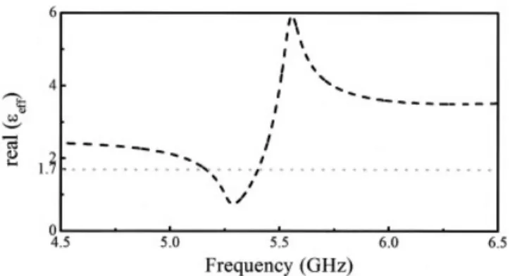
LHM structure along the direction of the propagation in our calculations. The orientation of the single layer LHM was that of Figure 2(a). We employed periodic boundary conditions along the directions other than the propagation direction. Hence, the simu-lation setup coincides with a slab of LHM that consists of a single layer. The dielectric constant of the PCB board was taken as 3.85. The PCB board has a thickness of 1.56 mm. The effective permit-tivities and permeabilities were derived from the transmission and reflection coefficients. We would like to comment that the results of such a calculation are directly related to the electric and mag-netic polarizabilities of a single feature because such a calculation does not involve the local field corrections due to other labyrinth features. The retrieval results for a single labyrinth structure with-out the wires on the back of the PCB board are plotted in Figures 5(a) and 5(b). First of all, the real part of the effective permeability attains negative values above a certain frequency. Both the real and imaginary parts of the permeability fit quite well to the relation eff ⫽ 1 ⫺ f2/2 ⫺ 02 ⫹ i. We used the following fitting parameters for both the real and imaginary parts of the effective permeability: f⫽ 0.1806 and ⫽ 0.0526. It is also interesting to observe that the imaginary part of the permeability attains quite high values in the close vicinity of the resonance frequency. This result indicates that the labyrinth structure shows a quite strong resonant behavior at the resonance frequency. We also calculated the real part of the effective permittivity. The results are shown in Figure 6. Notice that the permittivity is significantly increased just above the resonance frequency when compared to the effective permittivity of the host medium. The effective permittivity of the host medium was around 1.7 for our structure. This value was calculated by use of the relationeff ⫽ fi ⫹ 共1 ⫺ f 兲e. At 5.55
GHz, the permittivity of the labyrinth structure attains a value, 5.92, that is 3.5 times larger than the effective permittivity of the host medium. Hence, one should consider the dielectric response of the labyrinth structure around the resonance frequency when designing LHM mediums.
Figure 3 (a) Transmission spectrum of four-ring single labyrinth struc-ture with respect to orientations 1 and 2; (b) Transmission spectrum of two-ring single labyrinth structure with respect to orientations 1 and 2
Figure 4 Transmission spectrums of 5 layers of labyrinth based LHM medium with respect to orientations 1 and 2
Figure 5 (a) Real part of the effective permeability for a single layer of the labyrinth structure; (b) Imaginary part of the effective permeability for a single layer of the labyrinth structure
5. DESIGNING MEDIUMS WITH DESIRABLE PROPERTIES
We designed two labyrinth based LHM mediums (Figure 7), which are of particular interest, by the virtue of the above results. The first of these two mediums exhibits simultaneous , ⫽ 0 at a certain frequency. We will refer to this particular LHM medium as LHM 1. LHM 1 includes a single labyrinth and a single wire in the unit cell. The labyrinth structure is located at the front side and the wire is located at the back side of the PCB board. The width of the wire is 0.7 mm. The plasma frequency of wire only medium is 7.65 GHz [Fig. 1(a)]. Effective permeability and permittivity attains a value of 0 at 5.97 GHz. Moreover, LHM 1 is impedance matched at 5.97 GHz. The value of impedance at 5.97 GHz is 1. It is interesting to note that the Maxwell equations reduce to electro-static and magnetoelectro-static equations for a medium with simultaneous , ⫽ 0 [33]. As a result, such a medium does not support propagating waves. On the other hand, a medium with, ⫽ 0 is
impedance matched to free space. We believe that the experimen-tal realization of LHM 1 will lead to the exploration of several novel phenomena and applications such as the complete shielding of phase information, and beaming applications. The second LHM medium that we designed exhibits simultaneous, ⫽ ⫺1 at a certain frequency. We will refer to this second medium as LHM 2. There is a single labyrinth structure and two wires in the unit cell of the LHM 2. The labyrinth structure is located on the front and both wires are located on the back side of the PCB board. Both wires have a width of 0.3 mm. Total width of the wires is 0.6 mm. The plasma frequency of wires only medium is 9.66 GHz in this case [Fig. 1(b)]. The values of both the effective permittivity and permeability assume a value of⫺1 at 5.82 GHz. In addition, the value of impedance at 5.82 GHz is 1. We believe that LHM 2 is quite important for the realization of sub-wavelength imaging.
6. CONCLUSIONS
In summary, we proposed and demonstrated a robust method for tuning the plasma frequency of a wire medium. We studied the properties of the labyrinth structure with respect to different orienta-tions. Our results showed that the response of the labyrinth structure to various orientations is quite similar. We analyzed the effective medium parameters of the labyrinth structure by use of a retrieval procedure. The results of our calculations showed that the effective permeability of the labyrinth structure is negative above a certain frequency. Moreover, our calculations revealed that the labyrinth structure exhibits a rather strong dielectric response near the reso-nance frequency. Finally, we designed two particular left-handed mediums. One of the two mediums exhibits simultaneous, ⫽ ⫺1 and the other medium has simultaneous , ⫽ 0 at a certain frequency.
REFERENCES
1. J.B. Pendry, A.J. Holden, W.J. Stewart, and I. Youngs, Extremely low frequency plasmons in metallic mesostructures, Phys Rev Lett 76 (1996), 4773.
2. B. Pendry, A.J. Holden, D.J. Robins, and W.J. Stewart, Magnetism from conductors and enhanced nonlinear phenomena, IEEE Trans Microwave Theory Tech 47 (1999), 2075.
3. D.R. Smith, W.J. Padilla, D.C. Vier, S.C. Nemat-Nasser, and S. Schultz, Composite medium with simultaneously negative permeabil-ity and permittivpermeabil-ity, Phys Rev Lett 84 (2000), 4184.
4. A.A. Houck, J.B. Brock, and I.L. Chuang, Experimental observations of a left-handed material that obeys Snell’s law, Phys Rev Lett 90 (2003), 137401.
5. R.A. Shelby, D.R. Smith, and S. Schultz, Experimental verification of a negative index of refraction, Science 292 (2001), 77.
6. C.G. Parazzoli, R.B. Greegor, K. Li, B.E.C. Koltenbah, and M. Ta-nielian, experimental verification and simulation of negative index of refraction using Snell’s law, Phys Rev Lett 90 (2003), 107401. 7. K. Aydin, K. Guven, C.M. Soukoulis, and E. Ozbay, Observation of
negative refraction and negative phase velocity in left-handed meta-materials, Appl Phys Lett 86 (2005), 124102.
8. K. Aydin, K. Guven, M. Kafesaki, L. Zhang, C.M. Soukoulis, and E. Ozbay, Experimental observation of true left-handed transmission peaks in metamaterials, Opt Lett 29 (2004), 2623.
9. J.D. Jackson, Classical Electrodynamics
10. K. Aydin, I. Bulu, and E. Ozbay, Focusing of electromagnetic waves by a left-handed metamaterial flat lens, Opt Express 13 (2005), 7645–7652. 11. I. Bulu, H. Caglayan, and E. Ozbay, Experimental demonstration of subwavelength focusing of electromagnetic waves by labyrinth-based two-dimensional metamaterials, Opt Lett 31 (2006), 814 – 816. 12. A. Grbic and G.V. Eleftheriades, Growing evanescent waves in
neg-ative-refractive-index transmission-line media, Appl Phys Lett 82 (2003), 1815.
13. V.G. Veselago, The electrodynamics of substances with simulta-Figure 6 Real part of the effective permittivity for a single layer of the
labyrinth structure
Figure 7 (a) Real parts of the effective medium parameters for single layer of the labyrinth based LHM structure. LHM structure includes a single wire with a width of 0.7 mm in the unit cell; (b) Real parts of the effective medium parameters for single layer of the labyrinth based LHM structure. LHM structure includes two wires with a width of 0.6 mm in the unit cell
neously negative values of permittivity and permeability, Sov Phys Usp 10 (1968), 509.
14. A.M. Belyantsev and A.B. Kozyrev, Tech Phys 47 (2002), 1477. 15. B. Pendry, Negative refraction makes a perfect lens, Phys Rev Lett 85
(2000), 3966.
16. Y.-C. Huang, Y.-J. Hsu, J.-S. Lih, and J.-L. Chern, Transmission characteristics of deformed split-ring resonators, Jpn J Appl Phys, 43 (Part 2) (2004), L190.
17. P. Gay-Balmaz and O.J.F. Martin, Efficient isotropic magnetic reso-nators, Appl Phys Lett 81 (2002), 939.
18. C.R. Simovski and B. Sauviac, Role of wave interaction of wires and split-ring resonators for the losses in a left-handed composite, Phys Rev E 70 (2004), 046607.
19. B. Sauviac, C.R. Simovski, S.A. Tretyakov, Double split-ring resona-tors: Analytical modeling and numerical simulations, Electromagnet-ics 24 (2004), 317.
20. M. Shamonin, E. Shamonina, V. Kalinin, and L. Solymar, Properties of a metamaterial element: Analytical solutions and numerical simu-lations for a singly split double ring, J Appl Phys 95 (2004), 3778. 21. R. Marques, J. Martel, F. Mesa, and F. Medina, Left-handed-media
simulation and transmission of emwaves in subwavelength split-ring-resonator-loaded metallic waveguides, Phys Rev Lett 89 (2002), 183901.
22. R. Marques, F. Mesa, J. Martel, and F. Medina, Comparative analysis of edge-and broadside-coupled split ring resonators for metamaterial design—Theory and experiments, IEEE Trans Antennas Propag 51 (2003), 2572.
23. R. Marques, F. Medina, and R. Rafii-El-Idrissi, Role of bianisotropy in negative permeability and left-handed metamaterials, Phys Rev B 65 (2002), 144440.
24. N. Katsarakis, T. Koschny, M. Kafesaki, E.N. Economou, and C.M. Soukoulis, Electric coupling to the magnetic resonance of split ring resonators, Appl Phys Lett 84 (2004), 2943.
25. I. Bulu, H. Caglayan, and E. Ozbay, Experimental demonstration of labyrinth-based left-handed metamaterials, Opt Express 13 (2005), 10238 –10247.
26. D.R. Smith, S. Schultz, P. Markos, and C.M. Soukoulis, Determination of effective permittivity and permeability of metamaterials from re-flection and transmission coefficients, Phys Rev B 65 (2002), 195104. 27. T. Koschny, M. Kafesaki, E.N. Economou, and C.M. Soukoulis, Effective medium theory of left-handed materials, Phys Rev Lett 93 (2004), 107402.
28. T. Koschny, P. Markos, D.R. Smith, and C.M. Soukoulis, Resonant and antiresonant frequency dependence of the effective parameters of metamaterials, Phys Rev E 68 (2003), 065602.
29. T. Koschny, P. Markos, E.N. Economou, D.R. Smith, D.C. Vier, and C.M. Soukoulis, Impact of inherent periodic structure on effective medium description of left-handed and related metamaterials, Phys Rev B 71 (2005), 245105.
30. D.R. Smith, D.C. Vier, N. Kroll, and S. Schultz, Direct calculation of permeability and permittivity for a left-handed metamaterial, Appl Phys Lett 77 (2000), 2246.
31. X. Chen, T.M. Grzegorczyk, B.-I. Wu, J. Pacheco, Jr., and J.A. Kong, Robust method to retrieve the constitutive effective parameters of metamaterials, Phys Rev E 70 (2004), 016608.
32. X. Chen, B.-I. Wu, J.A. Kong, and T.M. Grzegorczyk, Retrieval of the effective constitutive parameters of bianisotropic metamaterials, Phys Rev E 71 (2005), 046610.
33. R.W. Ziolkowski, Propagation in and scattering from a matched metama-terial having a zero index of refraction, Phys Rev E 70 (2004), 046608.
© 2006 Wiley Periodicals, Inc.
HIGH-GAIN WIDEBAND LOW-PROFILE
ANTENNA
Rosa M. Mateos,1Christophe Craeye,1and Giovanni Toso2
1Universite´ Catholique de Louvain, Laboratoire TELE
Place du Levant, 2
1348 Louvain-la-Neuve, Belgium
2ESA/ESTEC
Antenna and Sub-Millimeter Wave Section Noordwijk, The Netherlands
Received 15 June 2006
ABSTRACT: When trying to increase the bandwidth of antennas based
on high-impedance surfaces, the radiation pattern tends to split near the resonance frequency of the artificial perfect magnetic conductor (PMC). This problem is solved here by reducing the size of the PMC in the E-plane and by making it nonperiodic in the H-E-plane. Using a dual-dipole as a radiating element, a 30% impedance bandwidth is achieved with directivity larger than 9 dB over the whole useful band. In view of the antenna’s horizontal dimensions, this is close to the maximum achiev-able directivity. The total antenna height is 0.15, where corresponds to the wavelength at the highest frequency. A study of the surface cur-rents on the patches supports the phenomena observed on the radiation patterns.© 2006 Wiley Periodicals, Inc. Microwave Opt Technol Lett
48: 2615–2619, 2006; Published online in Wiley InterScience (www. interscience.wiley.com). DOI 10.1002/mop.21987
Key words: wideband antennas; low-profile antennas; artificial
mag-netic conductors; metamaterials
1. INTRODUCTION
One of the most important applications of photonic band-gap materials in the field of antennas consists of providing perfect magnetic conducting (PMC) ground planes. PMCs allow horizon-tal antennas to be placed very close to the ground plane without being short-circuited by their image. The design parameters of PMC surfaces is under study in many different groups [1–5]. Given the relatively narrow bandwidth of artificial PMC surfaces, their application remains a challenge for broadband antennas. Good results for low profile antennas have recently been obtained for spiral antennas [6], with a limited bandwidth in terms of axial ratio. However, in this article we will focus on low profile broad-band antennas with a very good linear polarization at broadside. The profile of the antenna is defined from the ground plane backing the whole structure, and measured as a factor of min (min/x), wheremincorresponds to the wavelength at the highest operating frequency.
The radiation performances obtained over the whole useful band of an antenna placed above a PMC has not been analyzed in detail before. We have observed that for broadband designs the patterns at broadside tend to split near and beyond the PMC resonance. So, the direction of the maximum is no longer at broadside. This phenomenon is also visible in Best’s work [7], concerning the study on a bow–tie antenna above a mushroom-like EBG structure. In this article, special attention will be given to the regularity of the radiation pattern at broadside, over the whole useful frequency band. Finally, a design providing more than 9.2 dB of broadside directivity will be obtained with a reflection coefficient better than⫺10 dB over a 32.6% relative bandwidth, with amin/6.5 profile.
The work here presented is performed with the FEKO [8] software, a full-wave simulation tool based on the Method of Moments. Some validations have been carried out by comparing intermediate results with a homemade code (also based on the