PARTICLE SWARM OPTIMIZATION OF
DIPOLE ARRAYS FOR SUPERIOR
MIMO CAPACITY
Ugur Olgun, Celal Alp Tunc, Defne Aktas, Vakur B. Ertu¨rk, and Ayhan Altintas
Department of Electrical and Electronics Engineering, Bilkent University, Bilkent, Ankara 06800, Turkey; Corresponding author: [email protected]
Received 10 June 2008
ABSTRACT: The particle swarm optimization (PSO) technique is em-ployed to design MIMO arrays for superior capacity. A channel model based on the method of moments solution of the electric field integral equation is utilized with PSO for arrays of dipole elements. Freestand-ing and printed dipole arrays are analyzed and optimized. Their adap-tive performance in the MIMO channel is compared. Numerical results in the form of mean capacity, including comparisons with genetic algo-rithm results and measurements, are given. © 2008 Wiley Periodicals, Inc. Microwave Opt Technol Lett 51: 333–337, 2009; Published online in Wiley InterScience (www.interscience.wiley.com). DOI 10.1002/mop. 24027
Key words: MIMO; mutual coupling; planar printed arrays; method of moments (MoM); particle swarm optimization (PSO)
1. INTRODUCTION
Multiple input multiple output (MIMO) wireless communication systems refer to the technology where the system has higher spectral efficiency and link reliability due to smartly placed mul-tiple antennas both at transmitter and receiver [1, 2]. Owing to its ability of offering significant increase in data throughput and link range without additional bandwidth or transmit power, MIMO became one of the current themes of the wireless communications research.
Foreseeing that MIMO communication systems will be every-where in near future, it is envisioned that capability of designing these systems with optimum channel capacities will be handy. For a classic MIMO system in which the transmitter and/or receiver antennas are placed in a specified volume, it is important to determine the individual antenna lengths and locations together with number of elements used. Furthermore, for an adaptive MIMO system, deciding which elements to activate or how to terminate the parasitic elements such that the channel capacity is maximized is a significant issue.
Aforementioned optimization may be accomplished when a MIMO channel model, which has the ability of simulating real world cases, is armed with an optimization algorithm. Particle swarm optimization (PSO), a popular and yet evolving powerful optimization algorithm inspired by the swarm behavior [3], can be employed for this purpose. PSO is proven to be fast, efficient, and capable of solving a vast variety of complex computational elec-tromagnetics (EM) problems. For instance, recently in [4], PSO is utilized to design a broadband low-profile modified U-slot micro-strip antenna; whereas in [5], it is applied on linear antenna arrays used by broadcasting base stations. It should be stressed that an antenna optimization problem which aims to maximize the channel capacity provides a more natural approach for antenna synthesis, since it maximizes the quantity of true interest in any communi-cation system. The introduction of information theoretical cost functions in the design of antennas turns out to be a promising approach [6].
Simulating real world cases is a vital issue for the accuracy and reliability of the designs but this is hard to accomplish. The models
used to simulate the behavior of MIMO channels can yield accu-rate and reliable results only if they are well tested and experi-mentally verified. Hence, throughout this study a channel model with electric fields (MEF) [7] is utilized. MEF is a full-wave analysis technique based on the method of moments solution of the electric field integral equation for the evaluation of the MIMO channel matrix accurately. Furthermore, the technique is compu-tationally efficient that allows analyzing MIMO performance of arrays with large number of dipole elements. Finally, high perfor-mance arrays can be designed using a combination of MEF and optimization techniques.
In this article, MEF is combined with PSO, in order to design dipole arrays with superior MIMO capacity. First, the accuracy and numerical efficiency of PSO is demonstrated on a sample scenario. For this purpose, a predefined problem is solved first in a brute force manner and then with PSO. As PSO succeeds in solving the problem with great efficiency, MEF with PSO is benchmarked with genetic algorithm (GA)-based simulations and measurements of [6]. In [6], Migliore et al. designed an adaptive MIMO antenna system using GA and measured its channel capac-ity under various test conditions. MEF with PSO is employed to solve the same setup in [6], and it is observed that the results match with the simulations and measurements in [6] demonstrating the ability of both MEF and PSO in designing MIMO systems. Then examples of MIMO system designs of freestanding and printed dipoles are introduced. Uniform circular arrays (UCA) of free-standing dipoles are shown to be a reasonable choice for high MIMO capacity, though results for other array configurations outperforming UCAs are given. Adaptive MIMO array perfor-mance of printed dipole arrays with loaded parasitic elements is investigated and compared with that of freestanding dipole arrays. Organization of the article is as follows: The MIMO channel model is discussed and formulated in Section 2 and then a brief analysis of PSO outlining its working principle is provided in Section 3. Numerical results, testing details, and sample designs of MEF with PSO are given in Section 4. Finally, concluding remarks are presented. An ejttime convention is used and suppressed from
the expressions, where is the angular frequency.
2. MIMO CHANNEL MODEL WITH ELECTRIC FIELDS
As the scattering environment, we use a non-line-of-sight, three dimensional (3D), and single-bounce geometric model. It assumes a transmitter (TX) and a receiver (RX) array, and uniformly distributed scatterers. Assuming flat fading, the received signal vector, vrx, can be written in terms of the transmitted one, vtx, and
the additive white Gaussian noise vector, n , with zero mean independent identically distributed (i.i.d.) elements with unit vari-ance as
vrx
⫽ Hvtx
⫹ n. 共1兲 (1) In Eq. (1), H denotes the R ⫻ T channel matrix, where R and T are the number of antenna elements in receiver and transmitter arrays, respectively. Assuming channel knowledge only at the receiver side, an achievable data rate assuming a diagonal trans-mission covariance matrix Q ⫽ E关vtx
共vtx 兲h 兴 ⫽ PTI/T can be evaluated as C⫽ E
冋
log2冉
冏
I⫹ PT THH h冏
冊册
(2)where I is the identity matrix, . is the matrix determinant, PT
with (.)h
and E[.] denoting the conjugate transpose and expectation operations, respectively. Note that the information theoretic capac-ity of this channel under total power constraint PTis
C⫽ max{E(log2兩I ⫹ HQHh兩)}, (3)
Qⱖ 0
Tr共Q兲 ⱕ PT
which is very challenging to compute when H is not from an i.i.d. circularly symmetric Gaussian distribution, where Tr(.) is the trace operator. As a result, in the rest of the article, with a slight abuse of the terminology we will refer to the achievable data rate in (2) as the capacity of the system.
As mentioned before, for the accurate and efficient evaluation of channel matrix entries, a channel MEFs [7] is used. MEF evaluates the received voltages vector from the transmitted one, by successfully integrating full wave electromagnetic analysis of TX and RX arrays with any geometrical scenario. MEF algorithm is based on the superposition principle which utilizes the activation of TX elements one by one while others remain deactivated. Using the method of moments (MoM) solution of the electric field integral equation due to this activation vector of transmitted volt-ages, currents induced on TX elements are found.
The total radiated fields due to TX currents are calculated on the scatterers via the Green’s function of the environment (i.e., free space Green’s function for freestanding dipoles and grounded dielectric slab Green’s function for printed ones). Each scatterer is designated to be an isotropic radiator having a 2 ⫻ 2 dual polarized scattering coefficient matrix, entries of which are mod-eled as complex i.i.d. Gaussian random variables with zero mean and unit variance. Received voltage by each RX antenna is eval-uated via another MoM solution of system of linear equations, known side of which is formed by the total scattered fields im-pinging on RX elements.
As we now both have the received and transmitted signal vectors for one activation, we can evaluate one column of the channel matrix that we need in order to calculate the channel capacity. By activating the next element of TX array while keeping the rest deactivated and continuing this process until all elements are activated, the entries of channel matrix are obtained.
3. PARTICLE SWARM OPTIMIZATION
PSO is a population-based stochastic optimization technique in-spired by the social behavior of bee swarming, bird flocking, or fish schooling. In PSO, the swarm is initialized with a random population, namely particles. Particles search for optimum solution by flying through the problem space by following the current optimum particles. Each particle keeps track of its coordinates in the problem space and associates the position with the best solu-tion, pbest, it has achieved so far. Another best value that is tracked by the particle swarm optimizer is the best value obtained so far by any particle in the swarm and is called gbest.
In past several years, PSO has been successfully applied in many electromagnetic problems. It is demonstrated that PSO gets better results in an easier and faster way compared to other methods. The PSO concept requires, at each time step, accelerating each particle toward its pbest and gbest locations. Acceleration is
weighted by a random term, with separate random numbers being generated for acceleration toward pbestand gbestlocations.
xn,t⫹1⫽ xn,t⫹ vn,t⫻ ⌬t, (4)
vn,t⫹1⫽ K关vn,t⫹1⫻ U共0,1兲 ⫻ 共 pbestn,t⫺ xn,t兲 ⫹2⫻ U共0,1兲
⫻ 共gbestn,t⫺ xn,t兲兴, (5)
where xn,t and vn,t are the particle’s position and velocity in nth
dimension at instant t,⌬t is the time step which is chosen to be one, K is the constriction factor, U共0,1兲 denotes the uniformly distributed random numbers between zero and one, finally1and 2are the scaling factors that determine the relative pull of pbestand gbestof the particles, respectively. As stated and analyzed in [3], the optimal selection of constants mentioned above necessitates the choice of K to be 0.729, 1 to be 2.8 and 2 to be 1.3, thus removing the need for setting a maximum velocity limit.
Occasionally, particles pass beyond the boundaries of given solution space, hence adoption of a boundary policy to the algo-rithm is essential [8]. In order to enforce particles to search inside the solution space of interest, damping wall and invisible wall techniques suit our applications best and therefore are used in this study. In the damping wall technique, when a particle attempts to search outside the allowable solution space in one of the dimen-sions, it is relocated at the boundary of the solution space and the velocity component in that dimension is changed in the opposite direction and multiplied with a random factor between zero and one. In the invisible wall technique, particles are allowed to fly outside the allowable solution space in one of the dimensions, but assigned zero fitness values. Eventually, the particles are expected to return to the solution space since fitness values (i.e., the capacity values evaluated for cases represented by each particle) are larger inside the allowed space.
4. NUMERICAL RESULTS
We start by assessing the speed, accuracy, and computational cost of the PSO implementation. Next, we check the validity of the channel model that we used. Finally, results for sample MIMO wireless system designs with arrays of freestanding and printed dipoles are given.
We first solve a predefined problem in a brute force manner, i.e., without employing PSO. The mission is to obtain the highest possible channel capacity by using a two element fixed separation (i.e., 0.61) varying length (i.e., from 0.01 to 1 with 0.01 increments yielding 100 different lengths for each antenna) free-standing linear dipole array (FSLA) at the transmitter. The prob-lem is to find the optimum individual eprob-lement lengths of this transmitting FSLA. On the other hand, the receiver array is as-sumed to be fixed, i.e., an FSLA located 300 away from the transmitter in a broadside manner, formed by R ⫽ 10 uniform linear dipoles each of which is separated by a distance of /2. Elements of both TX and RX array have a radius of/200 and are matched to 50⍀ source and load impedances, respectively. Trans-mit SNR of the array is assumed to be fixed. The channel is modeled by locating S ⫽ 100 uniformly distributed scatterers around the transmitter within a spherical region (i.e., in the far zone of the transmitter) and the capacity results are obtained by simulating NR⫽ 1000 channel realizations. Result of the brute force solution is presented in Figure 1(a) which depicts that the highest capacity is achieved when lengths of two elements are equal to 0.46. Afterwards, PSO is applied to the abovementioned problem, and it is observed that the result of PSO coincides with that of brute force solution as depicted in Figure 1(b). Investigating Figures 1(a) and 1(b), it is noted that the brute force solution requires 1002⫽ 10,000 cost function evaluations (since the
ele-ment length for each antenna is quantized into 100 possible values) whereas PSO has completed it in less than 200 evaluations. This computational test proves the efficiency and accuracy of PSO in solving this sort of computational EM problems.
Second step of the validation of our implementation is to check how accurately MEF models the MIMO channel. This step utilizes
experimental measurements under real life conditions. For this purpose, the work done in [6] is used. In [6], Migliore et al. fabricated an Adaptive MIMO (AdaM) system of identical trans-mitter and receiver of freestanding (FS) dipole arrays with two active elements surrounded by six parasitic elements. The geom-etry of the AdaM system used is rather simple./2 length thin-wire dipole antennas were placed in a rectangular lattice of 2 ⫻ 4 square grids with edge length/4. Active elements were placed in the middle of the lattice and were/2 apart from each other. On the other hand, the parasitic elements were placed to surround the lattice. The details of the geometry are available in [6]. Active elements were terminated in 50 ⍀ dummy loads and parasitic elements were connected to microelectromechanical systems (MEMS) switches with impedances Zon ⫽ 76.6 ⫺ j426⍀ and Zoff ⫽ 5.2 ⫺ j8.8⍀ . Every antenna element was placed at a
height of 1 m from the floor. The measurements were made in a common office room of 8 m width and 3 m length. The measure-ment method was to measure each elemeasure-ment of the channel matrix
H separately by employing a vector network analyzer. The
trans-mitted SNR was selected so as to achieve a channel capacity of 4 bits/s/Hz solely with active antennas and the performance of AdaM system were evaluated with this transmitted SNR through-out the measurements.
In this work, MEF with PSO is configured to simulate the aforementioned measurement environment and employed to find the optimal channel capacity that can be achieved. When modeling the office room in which measurements were made, a scattering scenario of uniformly distributed 20 point scatterers is considered. The capacity results of AdaM are obtained by averaging the MIMO channel capacity over 1000 different channel realizations. Remaining parameters are set to be the same as those of measure-ments of [6]. Under these conditions, termination impedances of parasitic elements are altered to achieve the optimal channel
ca-pacity, i.e., simulate the experiment done in [6]. The results of MEF with PSO are depicted in Figure 2 [represented by MEF with PSO (FS)] along with the measurement and GA simulation results of [6], and they are all in very good agreement which proves the validity and accuracy of MEF in modeling MIMO channels. Figure 2 also shows that, for small number of cost function evaluations, PSO can reach higher capacity values than GA does; though after 80 evaluations, two optimization algorithms lead to approximately the same results.
At this point, both MEF and PSO are proven to be reliable, accurate, and efficient thus validating its use in MIMO system design. From now on, we may utilize them to design sample MIMO arrays for superior channel capacity.
UCA are among the most popular arrays that antenna engineers use in their designs. It is interesting to investigate whether other geometries can bring significant gains over them. For this purpose, we consider a volume of ⫻ ⫻ in which the varying number of antenna elements are going to be placed. In this volume, we employ MEF with PSO to find a better MIMO design than/2 length UCA. As a first step, we seek for an improvement over the circularity of uniform arrays, that is to say we look for optimum locations rather than playing with the individual lengths of anten-nas which are set to be the same as UCA (2D case). In the second step, we set PSO (3D case) completely free to change both the locations and the lengths of every individual element in the array. The geometry and environment that is used in this part of the work is exactly the same to the one used to prove the validity of PSO. Since UCA is known to be a good antenna engineering solution and an improvement over UCA is sought, one PSO particle is smartly initialized with a UCA design. This saved us from doing many fitness evaluations since with full random initialization PSO could first reach the UCA configuration and then try to improve that. Owing to all these smart tricks and the high speed of PSO, we manage to improve UCA by converging to configurations with optimal capacity within 700 evaluations.
Figure 3 shows that as the number of elements in the TX array increases while keeping the volume constant, the capacity in-creases until a point. It also suggests that UCA is still a good solution and even the best one when the volume is relatively small
Figure 1 Numerical validation of PSO. (a) Brute force solution with 10,000 cost function evaluations. (b) PSO solution yields the optimum configuration (L1⫽ 0.46, L2⫽ 0.46) with the maximum capacity (8.7
b/s/Hz) in 181 cost function evaluations. [Color figure can be viewed in the online issue, which is available at www.interscience.wiley.com]
Figure 2 Validation of MEF⫹PSO with both GA simulations and mea-surements of [6] for freestanding adaptive dipoles; and comparison of adaptive performance of printed dipoles obtained by MEF⫹PSO. [Color figure can be viewed in the online issue, which is available at www. interscience.wiley.com]
or the array gets larger. It should be noted that the capacity difference between the 2D and 3D case arises from the 3D’s ability to change the individual lengths of elements and to place them in nonstaggered, staggered, or collinear arrangements.
Up to this point, only FS dipoles have been taken into account in all of our MIMO array designs. Thus, as the next step MEF with PSO is used to investigate printed dipoles for superior channel capacity. An adaptive MIMO system of a printed TX array is optimized by expanding the work of [6] to printed dipoles. The scenario, geometry, and environment used in this new design are very similar to the ones in [6]. The main difference between them is, as expected, the geometry of the new TX, which is depicted in Figure 4. The dielectric slab on the ground plane is assumed to have a thickness of d⫽ 0.1 and a relative permittivity of r⫽ 3. The length of the dipoles is chosen as l ⫽ e/2, where e
⫽ /关0.5共r ⫹ 1兲兴1/ 2is the effective wavelength due to the
di-electric material; whereas their widths are considered to be/100. The other difference from [6] is about the termination impedances of the TX elements. For the sake of a fair comparison (i.e., to eliminate the effects of antenna impedance mismatch between printed and FS dipoles), the termination impedance of the printed dipole is matched to that of the FS one, and then connected to the MEMS switch mentioned before.
Figure 2 also depicts the MIMO channel capacity performance of printed adaptive TX array, represented by PSO with MEF (Printed). As the figure suggests, the performance of FS dipoles is slightly better than the printed case. For in depth investigation, solutions for all 4096 (212) possible terminations (since we have a
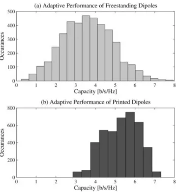
total of 12 parasitic elements and each of them can be either “on” or “off”) are obtained for both cases. The histograms of channel capacities for all possible solutions are given in Figure 5(a) for FS dipoles and 5(b) for printed ones. As can be seen from Figure 5, the maximum capacity for the FS adaptive array is larger than that of the printed adaptive array. The reason behind this result can be understood by inspecting the radiation patterns of single FS and printed dipoles in Figure 6 (note that both dipoles are x-directed). Figure 6(b) suggests that the radiation pattern of FS dipole on azimuth plane is isotropic whereas the one for printed dipole is curved due to the dielectric slab on the ground plane, leading to less radiated power under fixed transmit SNR. However, as Figure 5 suggests, the printed dipoles can be said to be less sensitive to the termination impedances based on the used MEMS switches in comparison with FS ones, since the minimum capacity of printed adaptive array is significantly larger than that of FS one; due to the fact that FS array elements are more mutually coupled than the printed ones for the configurations considered here. In the FS adaptive array, all elements are designed to be located at the maximum radiation direction of each other; and hence, FS array configuration given in [6] and this work suffers more from mutual coupling than the printed one does.
Figure 3 Capacity results obtained by PSO for freestanding dipoles in a 2area (2D), and a3volume (3D). Comparison with uniform circular
arrays (UCA). [Color figure can be viewed in the online issue, which is available at www.interscience.wiley.com]
Figure 4 Printed array geometry. [Color figure can be viewed in the online issue, which is available at www.interscience.wiley.com]
Figure 5 MIMO performance of adaptive arrays for all possible termi-nation impedances. (a) Freestanding dipoles. (b) Printed dipoles.
5. CONCLUSION
A channel model based on the method of moments solution of the electric field integral equation is combined with PSO to design MIMO arrays of dipole elements for superior capacity. Validation of both the channel model and PSO is done by comparing the results with measurements and GA simulations. Freestanding and printed dipole arrays are analyzed and optimized.
FS dipole arrays are designed for high MIMO performance by optimizing the number of antenna elements, their individual loca-tions, and lengths, in a physically limited volume. It is shown that, the use of UCA is a reasonable choice for high capacity, even though results for other array configurations outperforming UCA are given as well.
The work of [6] is expanded to printed dipole arrays, and their adaptive performance in the MIMO channel is investigated. Adap-tive printed dipoles are shown to be good alternaAdap-tives to FS ones, due to less mutual coupling; though their reduced radiated power under fixed transmit SNR leads to slightly decreased MIMO ca-pacity.
ACKNOWLEDGMENTS
This work has been supported by the Turkish Scientific and Tech-nical Research Agency (TU¨ BI˙TAK) under Grants EEEAG-106E081, EEEAG-104E044, and EEEAG-105E065; by Turkish Academy of Sciences (TU¨ BA)-GEBI˙P and also in part by the European Commission in the framework of the FP7 Network of Excellence in Wireless Communications NEWCOM⫹⫹ (contract no. 216715).
REFERENCES
1. I.E. Telatar, Capacity of multi-antenna Gaussian channels, Eur Trans Telecommun 10 (1999), 585–595.
2. G.J. Foschini and M.J. Gans, On limits of wireless communications in a fading environment when using multiple antennas, Wireless Pers Commun 6 (1998), 311–335.
3. J. Robinson and Y. Rahmat-Samii, Particle swarm optimization in electromagnetics, IEEE Trans Antennas Propag 52 (2004), 397– 407. 4. X.F. Liu, Y.C. Jiao, F.S. Zhang, and Y.B. Chen, Design of a low-profile
modified u-slot microstrip antenna using PSO based IE3D, Microwave Opt Technol Lett 49 (2007), 1111–1114.
5. Z.D. Zaharis, D.G. Kampitaki, P.I. Lazaridis, A.I. Papastergiou, A.T. Hatzigaidas, and P.B. Gallion, Improving the radiation characteristics of a base station antenna array using a particle swarm optimizer, Micro-wave Opt Technol Lett 49 (2007), 1690 –1698.
6. M.D. Migliore, D. Pinchera, and F. Schettino, Improving channel ca-pacity using adaptive MIMO, IEEE Trans Antennas Propag 54 (2006), 3481–3489.
7. C.A. Tunc, D. Aktas, V.B. Ertu¨rk, and A. Altintas, Capacity of printed dipole arrays in MIMO channel, IEEE Antennas Propag Mag, in press. 8. S. Xu and Y. Rahmat-Samii, Boundary conditions in particle swarm optimization revisited, IEEE Trans Antennas Propag 55 (2007), 760 – 765.
© 2008 Wiley Periodicals, Inc.
ELIMINATION OF THE
MULTIPLE-SOLUTIONS AMBIGUITY IN
PERMITTIVITY EXTRACTION FROM
TRANSMISSION-ONLY MEASUREMENTS
OF LOSSY MATERIALS
U. C. Hasar1,2
1Department of Electrical and Electronics Engineering, Ataturk
University, Erzurum 25240, Turkey; Corresponding author: [email protected]
2Department of Electrical and Computer Engineering, Binghamton
University, Binghamton 13902, NY Received 10 June 2008
ABSTRACT: A simple yet powerful method is proposed for removing the multiple solutions problem in the complex permittivity,, determina-tion from measured transmission scattering (S-) parameter measure-ments of lossy materials. The method uses amplitude-only measuremeasure-ments at two slightly separated frequencies to estimate an accurate initial guess. For this purpose, we derive a one-variable objective function for fast evaluation, which lends itself to measurement automation. The method provides an estimation for real and imaginary parts of the, which can be utilized as a measure for checking the correctness of initial estimate. The method is very useful for band-limited mea-surements. © 2008 Wiley Periodicals, Inc. Microwave Opt Technol Lett 51: 337–341, 2009; Published online in Wiley InterScience (www. interscience.wiley.com). DOI 10.1002/mop.24048
Key words: microwave measurement; permittivity measurement; scat-tering parameters
1. INTRODUCTION
Many applications in agriculture, biology, medicine, and civil engineering require the knowledge of complex permittivity,, of materials [1–3]. Physical, chemical, and mechanical properties of materials can be gathered from their interaction with electromag-netic waves by indirect methods via [4].
Measured reflection or transmission scattering (S-) parameters can be utilized for broadband extraction. However, measured transmission S-parameter (S21) has several advantages over mea-sured reflection S-parameter (S11) as: (a) it provides longitudinal averaging of variations in sample properties, which is particularly important for relatively high-loss heterogeneous materials such as moist coal and other powdered materials [5–7]; (b) it undergoes
Figure 6 Radiation patterns of x-directed freestanding and printed di-poles. [Color figure can be viewed in the online issue, which is available at www.interscience.wiley.com]