P l i l i § Л й Й ' І І Ш Ш І І І i ? й ^ KÎi P ]Ş Й; А ■rf(¿ vïv .d? 4 ’·< - »*■ a ^ ^ '_ A. я ^'"'ά \J t ùlÿ <*' M* ;^4 ; Tí ? í ' í % ÿi 7 ; Λ ‘ ! ji,ú. vf* Î 1 ,■· > '■> ■í*' Д:^X·. 'ЛЧ «·>* « · <^^1* w >¿ MiJ W '^4I( ■, Чи»‘ ^
1
л к (t ^ xwl«' ái ¡••f· ií >·\<, .sí •чУ «^'•«.■rfUV· ·*.■.> i« MhJİf Щ '■·:-.; .r» -·'.■■ i-Vv. '> ; . ; . ^7 ..'‘· ■ .·'..'■ 7.,'^· - . ■ '.·*·;.■ S! ^ '"í· ' í V“ ■■?: t.« *, ‘,1V.; J <,*'* «. -777: í-V^.···· '.. i. ·<■ .·ί<· .· ■' ■· ¿...;· ‘■•' .-■ ^ті> ^ ·■*: : :; 'O.PARALLELIZATION OF
HIERARCHICAL RADIOSITY ALGORITHMS
ON DISTRIBUTED MEMORY COMPUTERS
A T H E S I S S U B M I T T E D T O T H E D E P A R T M E N T O F C O M P U T E R E N G I N E E R I N G A N D I N F O R M A T I O N S C I E N C E A N D T H E I N S T I T U T E O F E N G I N E E R I N G A N D S C I E N C E O F B I L K E N T U N I V E R S I T Y IN P A R T I A L F U L F I L L M E N T O F T H E R E Q U I R E M E N T S F O R T H E D E G R E E O F M A S T E R O F S C I E N C E
By
Ahm et Reşat Şireli January, 1999
Ίιί)3?’ - Μ y «I /ή- > У. '■ 5 S f ,: ' Γ
Ö
11
I certify that I have read this thesis and that in my opin ion it is fully adequate, in scope and in quality, as a thesis for the degree of Master of Science.
S ^ J rh rL ·
Asst. Prof. Attil§ Giirsoy (supervisor)
I certify that I hcive read this thesis and that in my opin ion it is fully adequate, in scope and in quality, as a thesis for the degree of Master of Science.
Assoc, ^ ’of. Cevdet Ayktinat
I certify that I have read this thesis and that in my opin ion it is fully adequate, in scope and in quality, as a thesis for the degree of Master of Science.
gur Güdükbay
Approved for the Institute of Engineering and Science:
Prof. Mehmet ti^a.y
A B S T R A C T
PARALLELIZATION OF
HIERARCHICAL RADIOSITY ALGORITHMS ON DISTRIBUTED MEMORY COMPUTERS
Ahmet Reşat Şireli
M.S. in Computer Engineering and Information Science Supervisor: Asst. Prof. Attila Giirsoy
.lanuary 1999
Computing distribution of light in a given environment is an important prob lem in computer-aided photo-realistic image generation. Radiosity method has been proposed to address this problem which requires an enormous amount of calculation and memory. Hierarchical radiosity method is a recent cipproach that reduces these computational requirements by careful error analysis. It has its idea from the solution methods of N-body problems. Although hier archical approach has greatly reduced the amount of calculations, satisfactory results still cannot be obtained in terms of processing time. Exploiting paral lelism is a practical way to I'educe the computation time further. In this thesis, we have designed and implemented a parallel hierarchical radiosity algorithm for distributed memory computers. Due to its highly irregular computational structure, hierarchical radiosity algorithms do not yield easily to paralleliza tion on distributed memory machines. Dynamically changing computational patterns of the algorithm cause severe load imbcilances. Therefore, we have developed a dynamic load balancing technique for the parallel hierarchical ra diosity calculation.
Keywords: Realistic Image Genercition, Parallel Hiei'circhical Radiosity, Dy
namic Load Balancing.
ÖZET
DAĞITIK BELLEKLİ BİLGİSAYARLARDA SIRADÜZENSEL IŞIMA ALGORİTMALARININ
PARALELLEŞTİRİLMESİ
Ahmet Reşat Şireli
Bilgisayar ve Enformatik Mühendisliği, Yüksek Lisans Tez Yöneticisi: Yard. Doç. Dr. Attila Gürsoy
Ocak 1999
Işığın verilen ortam içerisinde dağılımını hesaplamak bilgisayar destekli gerçeğe uygun görüntü üretiminde önemli bir problemdir. Işıma metodu, bu aşırı bir miktarda hesap ve hafıza gerektiren problemin çözümü için önerilmiştir. Sıradüzensel ışıma metodu, bu işlemsel gereksinimleri dikkatli hata analizi sonucu azciltan nihai yaklaşımlardan biridir. Fikrini N-gövde probleminin çözüm metodlarmdan almıştır. Sıradüzensel yaklaşım izlemlerin miktarını büyük ölçüde azaltmış olmasına rağmen, zaman bakımından tatminkar sonuçlar hala elde edilememektedir. Paralellikten faydalanmak işlemsel sürenin daha da azaltılması için pratik bir metoddur. Bu tezde, dağıtık bellekli bilgisayarlar için bir paralel sıradüzensel ışıma algoritması tasarladık ve uyguladık. Aşırı düzensiz işlemsel yapısı yüzünden sıradüzensel ışıma algoritmaları dağıtık bellekli bilgisayarlar üzerinde paralelleştirilmesi kolay olmamaktadır. Algoritmanın dinamik olarak değişen işlemsel örüntüleri birçok yük dengesizliklerine sebej) olmaktadır. Bu yüzden paralel sıradüzensel ışıma algoritmamız için bir dinamik yük dengeleme tekniği de geliştirdik.
Anahtar sözcükler: Gerçeğe Uygun Görüntü Üretimi, Paralel Sıradüzensel
Işıma, Dinamik Yük Dengeleme.
A C K N O W L E D G M E N T S
First and foremost, I would like to express my deejDest thanks and gratitude to my advisor Asst. Prof. Attila Giirsoy for his patient supervision of this thesis.
I am grateful to Assoc. Prof. Cevdet Aykanat and Asst. Prof. Uğur Güdükbay for reading the thesis and for their instructive comments. I would like to acknowledge the financial support of TÜBİTAK under the grant EEEAG- 247.
Special thanks go also to Asst. Prof. Uğur Güdükbay for providing the substance of this research work and to Assoc. Prof. Cevdet Aykanat for permitting us to use the machine Parsytec CC (through ITDC 204-82166 and TÜBİTAK EEEAG-160).
I would also like to thank my family for their encouragement; my sister Filiz, my friends Önder, Seher and Yücel for their moral support; and finally all other friends who contributed this study.
To my family, to infinity and beyond
Contents
1 Introduction 1
2 Asynchronous Message Handling 4
2.1 Asynchronous Message Handling... 4
2.2 Converse and Its Machine In te rfa c e ... 6
2.3 The Underlying System, Parsytec C C ... 7
2.4 Im plem entation... 8
2.4.1 A-.sender 1-receiver Version... 10
2.4.2 A-sender A-receiver V e r s io n ... 12
2.5 Performance Evaluation 12 2.5.1 Communication via R i n g ... 13
2.5.2 K-to-all Broadcast C om m u n ica tion ... 13
2.6 C onclusion... 14
3 Hierarchical Radiosity 16 3.1 Radiosity 16 3.1.1 Form Factor C a lcu la tio n ... 19
3.1.2 Visibility C alcu lation ... 21
3.1.3 The Ambient T e r m ... 23
3.2 Hierarchical Radiosity 24 3.2.1 Hierarchical Radiosity vs. O t h e r s ... 25
3.3 Design of An Object-Oriented Hierarchical Radiosity Program . 27 3.3.1 Algorithm of Hierarchical R a d io sity ... 29
3.4 Further Improvements on Radiosity Process 36 4 Parallelization of Hierarchical Radiosity 37 4.1 In trodu ction ... 37
4.2 Characteristics of Radiosity D a t a ... 37
4.3 Previous Work 38 4.4 The Underlying System ... 40
4.5 Design ... 41
4.5.1 Dynamic Load Balancing and Patch Migration . . . 47
4.5.2 Subdivision Depth L i m i t ... 48
4.5.3 Visibility C alcu lation ... 48
4.5.4 Message-Driven E x e c u tio n ... 49
4.5.5 A lg o r ith m ... 49
4.5.6 Object Oriented Design 50 4.5.7 Flow of the A lg o r it h m ... 54
4.6 Performance C on sid era tion s... 60
4.6.1 Load B a la n cin g ... 61 4.6.2 Load Estimation 62 4.6.3 Initial D is tr ib u tio n ... 64 4.6.4 Patch M igration... 66 5 Performance Evaluation 75 5.1 The Input S c e n e s ... 75 5.2 Impact of Load Estimation Methods 77 5.3 Impact of Initial Patch D istribution... 77 5.4 Impact of Dynamic Load B alan cin g ... 81 5.5 Impact of Patch Subdivision Depth L im it... 81
6 Conclusions and Future Work 89
List of Figures
2.1 Port environment... 8 2.2 Communication model of Al-sender 1-receiver version... 10
.3.1 Surface types... 18 3.2 Form factor geometry. 20 3.3 Sample hierarchical interactions... 2-5 3.4 Sample interactions of progressive radiosity. 26 3..5 Rays fired from a quadrilateral to a triangle to detect occlusion. 32 3.6 Subdivision of a quadrilateral and a triangle... 3.5
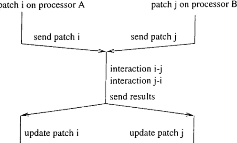
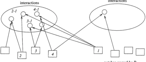
4.1 Evaluating an interaction on a processor which does not own any of the interacting patches... 42 4.2 Evaluating an interaction on both of the processors which own
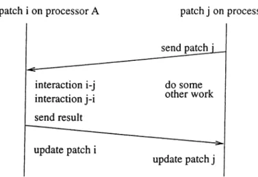
the interacting patches... 43 4.3 Evaluating an interaction on one of the processor which owns
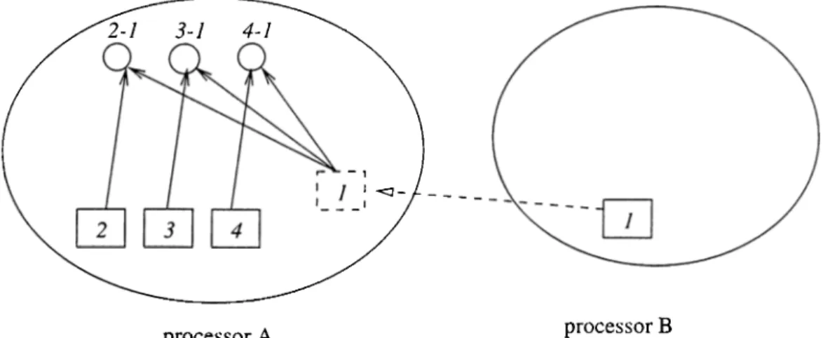
any of the interacting patches... 43 4.4 Interactions across processors... 44 4.5 Interactions using proxy patches. 45
4.6 Interactions using proxy manager... 47
4.7 Base and inherited classes for patches and proxies... 50
4.8 Parts of a global id. consisted of 4 bytes... 51
4.9 Indexing strategy of all of the existing patches... 52
4.10 Work flow in an iteration (without migration)... 55
4.11 Patch migration. 66 4.12 Subpatch migration. 67 4.13 Moving interactions of a migrated patch... 69
4.14 Subpatch migration problem. 73 5.1 Scene 1, wireframe picture... 85
5.2 Scene 2, wireframe picture... 86
5.3 Scene 3, wireframe picture... 86
5.4 Scene 4, wireframe picture... 87
5.5 Scene 1, shaded image... 87
5.6 Scene 4, shaded image... 88
List of Tables
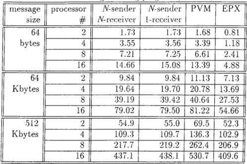
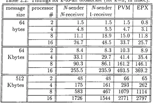
2.1 Timings for ring program (in m sec)... 14 2.2 Timings for k-to-all broadcast (for k==n, in m.sec)... 15
4.1 Sample execution results for one of the processors. 62
5.1 Scenes used in performance studies (results are for one processor). 77 5.2 Comparison of load estimation methods (input order patch di,s-
tributing method) (p; according to patch number, i: according to interaction number, f: according to the presented formula). 78 5.3 Comparison of load estimation methods (octree-based patch dis
tribution) (p: according to patch number, i: according to inter action number, f: according to the presented formula). 78 5.4 Timings for sample runs of different patch distribution methods. 79 5.5 Communication volumes for sample runs for different patch se
lection methods... 80 5.6 Statistics for runs including migration with random patch
dis-tribution( *: no migration required, **: migration failed within
given limits). 82
5.7 Statistics for runs including migration with input order patch distribution (*: no migration req u ired .)... 83
LIST OF TABLES xni
5.8 Statistics for runs including migration with octree-based patch distribution (*: no migration required)... 84 5.9 Statistics for sample runs with different subdivision depth limits
Chapter 1
Introduction
Photo-realistic image generation is a difficult and time-consuming problem of computer graphics. Difficulty arises because of the necessity of sirtiulating the real-world lighting events with considering all the possible physical effects. For mulation may not be enough to express events completely. Time-consuming property is due to its enormous amount of calculation requirement which is reversely proportional with the quality of image. While wishing to develop a real-time interactive image generator, we still have to wait for minutes even for simple scenes. Despite of all these negative factors, it still preserves its attractiveness for the researchers. Combined with animation, image genera tion is a very promising subject that has too many application cxreas such as simulating, training, design and manufacturing, telecommunications, medicine, information visualization. Although it may seem as a very difficult problem today, technological improvements will never stop and one day we will be able to use it in our daily life.
An important problem in achieving realistic image generation is computing the distribution of light in an environment. Radiosity approach has been pro posed to solve this problem [GTGB84] whose principles are based on a research area of thermodynamics, heat transfer. Instead of heat transfer, we consider energy transfer between surfaces, in radiosity method. The method requires all of the surfaces in scene to exchange light energy according to some configu ration factors. Calculation of these configuration factors is the most important
and time-consuming part of racliosity method.
Hierarchical radiosity is a recent approacli that reduces computational re- cjuirements by careful error analysis. It has its idea from the solution methods of N-body problems. N-body solution methods appro.xirnate the interactions between well separated groups of objects by a single interaction. Consecpiently many expensive calculations that have little effect on the accurcicy of the solu tion can be avoided. Hierarchical radiosity applies this approach by eliminating the interactions of surfaces that do not effect the accuracy of the overall solu tion. Criterion of efficiency of an interaction is the radiant flux carried by it. As stated in [CW9.3], hierarchical technicjues reduce the complexity of radiosity computations from O(n^) to 0{n-\-k^), where k is the number of input surfaces, and n is the total number of resultant elements in an environment (n k).
Although hierarchical approach has greatly reduced the amount of calcu lations, satisfactory results still cannot be obtained in terms of time. As we mentioned in the beginning, none of the methods can achieve image production in a reasonable time with a reasonable accuracy yet. Parallel processing is one of the most practical ways to reduce the computation time further. Due to its highly irregular computational structure, hierarchical radiosity algorithms do not yield easily to parallelization on distributed memory machines. In this the sis, we investigate the feasibility of parallel processing for hierarchical radiosity. This work consists of three main parts:
• design of a parallel algorithm and dynamic load balancing mechanisms for radiosity,
• design and implementation of a parallel object-oriented program, and • performance study and impact of various design decisions.
CHAPTER 1. INTRODUCTION 2
The parallel algorithm is based on the sequential hierarchical radiosity algo rithm presented in [HSA91]. The algorithm we proposed can also be extended to the recent improvements on this field, such as clustering, lazy linking etc. The object-oriented implementation has been done using Charm-f-(- program ming environment. Charm T+ is a parallel object-oriented language developed
at UIUC [KK93]. As part of this thesis work, we also ported Charm ++ to the Parsytec CC^ distributed memory machine to conduct the performance studies.
The thesis is organized as follows. Section 2 presents a study on asyn chronous message handling strategies. First, we make cin overview of asyn chronous rnessage handling strategies, and then present a study about porting Charm-t--|-/Converse to Parsytec multicomputer [ACSG98]. The objective of this study is to investigate performance of the system that we are going to use for the rest of the study.
Section 3 gives a description of the radiosity problem and the hierarchical model. Concepts of the problem and solution methods are discussed briefly. We also present a design of sequential version of the hierarchical radiosity algorithm including some implementation issues. This study is performed in order to separate the issues related with parallelization as much as possible.
Section 4 discusses parallelization of the hierarchical radiosity algorithm in detail. After an overview of related work, we explain and discuss our design and implementation issues. We also discuss performance issues such as load balancing, at the end of the section.
In Section 5, this work is evaluated with performance results. Timings are presented for sample scenes and impacts of some design decisions on perfor mance are analyzed.
The thesis finishes by concluding the studies in the last section. Including the critique of our implementation, future work is also provided. The goals met are stated, those unmet are discussed.
CHAPTER 1. INTRODUCTION 3
Chapter 2
Asynchronous Message
Handling
In this chapter, we make an overview of asynchronous message handling strate gies and present a study about porting Charm-f-j-, which is a parallel object- oriented language, to Parsytec multicomputer. Porting Charm-|--f- to a new machine requires reimplementation of some parts of its machine dependent layer. This machine layer in Charm-t--)- belongs to a component called Con verse (an interoperable framework for parallel programming). Therefore, we have implemented machine dependent layer of Converse for the Parsytec com puter.
The motivation behind this work is to use advantages of Charm-|--j- pro gramming environment not only for the parallel implementation of hierarchical radiosity, but also for other applications that might be developed later. The details of this port and the advantages of Charm-b-f environment is discussed in the following sections.
2.1
Asynchronous Message Handling
The major source of performance degradation in message passing parallel com puters is the delays due to communication which is an inevitable requirement.
CHAPTER 2. ASYNCHRONOUS MESSAGE HANDLING
These delays are not only due to latencies in the communication network. A significant portion of it is due to software overhead to handle sending and re ceiving messages from user level to the hardware level. Due to its unavoidable and unnegligible impact on performance, parallel system designers spend great efforts to build systems which minimize rnesscige processing overhead, in ad dition to hardware improvements. Asynchronous message handling is such a study which aims to reduce this delay by handling messages efficiently at the receiving side. This is achieved by overlapping communication with computa tion and providing an efficient mechanism to handle the incoming message.
Asynchronous message handling is useful in irregular applications in which sending and receiving of messages are performed in a non-deterministic order. This is frequently the case in applications of parallel object-oriented systems. Processes in such systems do not operate in a synchronized manner and there fore cannot know when to expect incoming messages. It is possible to receive messages synchronously by regularly polling the network, however achieving good performance with a polling-based approach is not easy [LBB97]. Another way is using interrupts to deliver the incoming message. However, as discussed in [LBB97], polling network is much cheaper than using interrupts.
In contrast to message passing, in asynchronous message handling model message reception results in invocation of a function, which is called mes sage handler. Expressiveness of the message handler is an important factor in achieving good performance. There are several asynchronous message handling systems developed (e.g. [ECGS92], [PLC95]) and they vary in the way the han dlers are executed, the expressiveness of the model etc. Less expressive models restrict functions of a message handler in order to be more efficient, whereas more expressive models do not put restrictions on message handlers in order to be more expressive. The less the expressiveness, the more the efficiency is.
Active messages model [ECGS92] is an example of restrictive model. It restricts blocking of message handlers. Also, message handlers cannot allo cate memory or initiate communications to other processors. Because message handlers do not have their own execution context. Thei'efore, there is no a different stack, no thread definition and no thread switching. Although these
features make the model very effective, they significantly cornpliccite program ming. Other mechanisms include single-tlireaded upcall and pop-up threads, which disallow all blocking by letting message handlers use locks to synchronize their shared-data accesses.
Asynchronous message handling deals with only reducing the software over head of sending and receiving a messcige. However, the physical reality dictates that accessing a remote information will always be slower than accessing the lo cal one. Hence, in addition to reducing the delays, overlapping these delays due to remote data access with useful computation is also important for improving performance of parallel systems. Message driven execution is a promising model in this sense [KG95]. In message driven execution, there are many objects per processor. When a message arrives for an object, the object is eventually ac tivated with the message. Although message driven execution sounds similar to asynchronous message handling, it requires a scheduler. In asynchronous message handling the invocation of handlers is not under the control of user and they lack user level scheduler. Converse [KB.JK96] is one of the early im plementations of a parallel programming system that combines scheduler with asynchronous message handling. A brief information about Converse is given in the next section.
In the rest of the chapter, we will discuss porting Converse to Parsytec CC parallel computer.
CHAPTER 2. ASYNCHRONOUS MESSAGE HANDLING 6
2.2
Converse and Its Machine Interface
Generally speaking, Converse is a library of subroutines for parallel processing. In contrast to traditional receive based message passing. Converse [KBJK96] is a message-driven parallel programming language which combines user level scheduler with asynchronous message handling.
Converse is a portable language which has been implemented on various machines such as Origin 2000, IBM SP3, CM5, Cray T3E etc. Converse Ma chine Interface (CMI) contiiins functions which must be implemented to port
Converse to a parallel computer. The CMI module is responsible for process creation and coordination cit the communication and some other utilities such as timers required for portability. TIk; functions contained in CMI ciin be grouped under the following headers:
• Message sending functions: CmiSyncSendO, CmiAsyncSendO and
their variants.
• Message broadcasting functions: CmiSyncBroadcast (), CmiAsyncBroadcast 0 and their variants.
• Initialization/termination functions: Converselnit (), ConverseExit () • Neighbor determination functions: CmiMyModeO, CmiMumNodesO,
CmiMyRankO, CmiRankOf () and a few more.
• M em ory allocation/free functions: CmiAllocO, CmiFreeO, CmiSizeO • Handler related functions: CmiSetHandlerO, CmiGetHandlerO,
CmiGetHandlerFunctionO
In this work, we consider minimal interface of the message sending functions. Complete information about the CMI functions is available in [CON96].
CHAPTER 2. ASYNCHRONOUS MESSAGE HANDLING 7
2.3
The Underlying System, Parsytec CC
The Parsytec CC system is a parallel computer manufactured by Parsytec GbmH in Aachen, Germany. It is based on distributed memory MIMD archi tecture. All nodes of Parsytec CC system run the AIX operating system with EPX, Embedded Parix on top. EPX provides set of functions to build and to use a communication network and to define suitable routines managing data operations.
There are three types of communication available in EPX. These are namely synchronous virtual link bound communication, synchronous random commu nication cuid asynchronous link bound communication. PVM is also available in the system.
CHAPTER 2. ASYNCHRONOUS MESSAGE HANDLING
Figure 2.1: Port environment.
2.4
Implementation
Porting Converse to Parsytec was a study of bridging the gap between CMI and EPX (see Figure 2.1). We implemented the CMI machine interface on top of EPX, which is the native message passing library of Parsytec CC machine. However, the functionality of EPX message passing primitives is not sufficient to express all the CMI primitives directly. One of the problems is that syn chronous message passing functions of EPX blocks the caller until the tail of message enters the network. In Converse, however, the control must return to the caller just after the send function call. Asynchronous primitives of EPX are not compatible with CMI asynchronous functions either. The problem is that in EPX a sender processor cannot detect whether a particular message is reached the destination or not, during cisynchronous communication. Rather, it can only check if there exists any message on the link that the message is sent through. Another problem is about the size of messages that are to be transmitted. EPX receive primitives require size of messages in advance. But EPX does not support functions to evaluate the size of the incoming message, rather it is maintained by the programmer. On the other hand Converse does not know which message is going to be received next. Therefore we developed an efficient mechanism to receive arbitrary size messages.
To overcome problems related with asynchronous message sending and re ceiving, we have designed-a layer containing threads and message queues. That is on each processor, the main thread (the process) executes the scheduler of
Converse. The messages are sent and received by separate threads which are responsible for communication, within the process. These threads perform message passing by calling EPX functions. So there are sender and recei\er threads. A receiver thread checks the incoming transmission links with which it’s associated, and as it detects a message on any of those links, it receives the message using RecvLinkO primitive and appends it into the receive queue of its owner processor. When a messcige is detected in receive queue, it is picked up rapidly by the scheduler using CmiGetNonLocalO function and associated hcindler function is invoked with necessary parameter that is with the message itself. Sender threads are responsible for sending messages which are picked up from send queues, to related processors. Respectively when a message is detected in any send queue, it is transmitted into the network using EPX
SendLinkO primitive.
We had some alternatives for the number of sender and receiver threads. These were:
• 1-sender 1-receiver • A-sender 1-receiver • 1-sender A-receiver • A-sender A-receiver
CHAPTER 2. ASYNCHRONOUS MESSAGE HANDLING 9
where A is number o f nodes - 1 . We found it better to use A send queues and A sender threads, which each thread associated with a separate message queue and a processor, in order to avoid contention on queues on concurrent send requests to different target processors. For the receiving threads, however, we needed to maintain a single queue for incoming messages to keep the First- In-First-Out (FIFO) order. Using one receive thread results better than using A number of receive threads, since in the latter case the threads will waste CPU time sharing the single receive queue. The one-and-only receive thread uses the S e le c tL istO function of EPX in order to wait messages from all transmission links. In order to make comparison, we also implemented the A receiver version. The versions are discussed in the next sections.
CHAPTER 2. ASYNCHRONOUS MESSACE HANDLINC 10
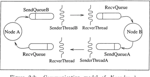
Figure 2.2: Communication model of A'^sender 1- receiver version.
For message size problem, we developed an efficient mechanism to receive arbitrary size messages by defining a standard message size SIZE. The mech anism works as follows: The messages that are less than SIZE bytes are sent directly without an extra work. Longer messages are sliced into 2 -parts. Size information is appended to the last 10 bytes of the first part and totally SIZE-(-l bytes are sent in the first communication. The rest of the message is sent in the second communication as a whole. When the receiver receives a message with size of 1 to SIZE bytes, it understands that the whole message has been received. If the message is SIZE+1 bytes, it reads the size information from the last of 10 bytes of the message, allocates that much buffer, copies the first part of the message to this buffer and receives the rest of the message to be placed next to the first part in the buffer.
2.4.1
iV-sender 1-receiver Version
The first step to implement an EPX program is to select an appropriate topol ogy. Converse is a system which requires direct communication between any two nodes. E P X ’s virtual topology library supports clique topology which satis fies this requirement. However, we observed that creating completely connected topology explicitly with C reateL in kO function, gives better performance in terms of communication speed. And also the function S e l e c t L i s t O we used requires links to be created explicitly.
CFIAPTER 2. ASYNCHRONOUS MESSAGE HANDLING
The communication model is seen on F'iguro 2.2. The model is valid ior every pair of nodes. Each node hcis N sender tlireads and N send queues each associated with a particular processor. The receive thread and the receive queue is only one in each node.
In order to prevent the sender threads to be active and using CPU while there is no message to be sent, we used semaphore mechanism. The idle threads wait in a lock to acquire a semaphore which will be released when there is a message to be sent. Also, exclusive usage of message queues are provided by semaphores.
The function we used to decrease the number of I’eceiver threads is the
S e le c tL istO call, which provides receiving message from any node. It returns
the identifier of the node which tries to send a message to that node. A receiver thread waits for new messages to be received fi’om any processor by calling this function. As soon as the arrival of a message, the thread appends the message to the tail of message queue.
A sender thread waits for the messages to be sent in a blocked position. It tries to acquire a semaphore which will be released when a new message is appended to its message queue. When it acquires the semaphore, it takes the appended message from the queue and send it. The sender threads are used only for asynchronous send requests. To speed up the communication, synchronous send requests are performed by directly calling SendLinkO func tion of EPX. These two different approaches may lead a change in the order of messages. In order to preserve the order, the synchronous send requests are performed only after providing that there are no messages to be sent waiting in the queues.
Let’s see how a send request is performed, on the nodes presented in the Figure 2.2. Node A wants to send a message to node B using asynchronous communication. It appends the message to the message queue, sendQueueB
and releases semaphoreB to activate senderThreadB which waits as having been blocked. The call returns immediately with the pointer of queue element where the message is kept. By the help of this pointer, it can be checked whether the communication is done or not. SenderThreadB picks up the message from its
CHAPTER 2. ASYNCHRONOUS MESSAGE HANDLING 12
queue immediately and invokes a send call to node JJ. Receiver Thread receives the message rapidly and appends it to the recvQueue. As soon as the com munication is completed, the message is retnoved from the message queue. At the end, the scheduler of node B calls CmiGetMonLocal( ) , picks up a message from the received message queue recvQueue and processes it.
Broadcast operation is also realized by threads. The message is appended to all of the message queues of the sender threads one by one. For synchronous broadcast operation, we wait for the end of all sending operations. However, for asynchronous type, we return the control to the caller procedure immediately. Sender threads pick up the message rapidly and try to send them to all other nodes of the system. In asynchronous broadcast operation, we have a chance to overlap computation and communication, since there is no a blocking type operation.
2.4.2 iV^sender iV-receiver Version
Different from the 1-receiver version, there are receiver threads in each node. This version is implemented to compare the overhead of using more receiver threads with using S electL istO call. In this version no S electL istO is called since there are already N receiver threads instead of that call. Since all the receiver threads uses only one message queue, accesses to this queue is restricted. Mutual exclusion is provided by semaphore mechanism.
2.5
Performance Evaluation
In order to measure and compare performances of the asynchronous message handling (Converse) and the message passing libraries which are available on Parsytec CC system, namely EPX [EPX95] and PVM [GBD+94], we conducted a performance study. The study included a simple ring communication algo rithm for measuring message latency as observed by the programmer, and the k-to-all broadcast algorithm. Message-driven execution has advantages if mul tiple messages arrive in an unpredictable order and if they can be processed
CHAPTER 2. ASYNCHRONOUS MESSAGE HANDLING i;}
not in a strict order. K-to-all broadccist wlierc! multiple messages arrive in an unpredictable order demonstrates this advantage. The algorithms have been implemented using EPX, PVM, and Converse systems as efficient as possible for each case.
2.5.1
Communication via Ring
In the ring program, the processors are connected such that they form a ring topology, and they pass messages from their predecessors to their successors. When the processor that has sent the message first, receives the rnesscxge from its predecessor, the ring computation finishes. The communication is regular in the sense that there is only one message and each processor knows from where to receive and to where to send the message. Table 2.1 shows the round-trip time for messages of different length for Converse, PVM and EPX versions of ring. The EPX version is slightly faster than PVM and Converse ones because Converse and PVM runtime systems are built on EPX and the difference is the software overhead introduced by Converse and PVM systems. However, as the messages get larger. Converse results start becoming better than PVM and get closer to EPX results. So, Converse incurs negligible overhead for having the capability of asynchronous message handling. The next example, k-to-all broadcast shows a significant performance improvement in case of handling multiple messages.
2.5.2
K -to-all Broadcast Communication
In k-to-all broadcast, k processors simultaneously perform a one-to-all broad cast of m-word messages. The broadcast operation is implemented by forming a spanning tree covering all the processors where the root node is the initiator of the broadcast. Table 2.2 shows the completion time of k-to-cxll broadcast. In this case, there are multiple broadcast operations going on concurrently. There fore, in the EPX and PVM version, these messages are handled in a fixed order however in Converse version the messages trigger the appropriate operations as they arrive. As shown in the figure, the Converse version is significantly
CHAPTER 2. ASYNCHRONOUS MESSAGE HANDLING 14
Table 2.1; Timings for ring program (in msec). message size processor # A^-sender ^receiver A^-sender {-receiver PVM EPX 64 bytes 2 16 1.73 3.55 7.21 14.66 1.73
1.68
3.56 3.39 7.25 6.61 15.08 13.39 0.81 1.18 2.41 4.88 64 Kbytes 16 9.84 19.64 39.19 79.02 9.84 11.13 19.70 20.78 39.42 40.64 79.50 81.22 7.13 13.69 27.53 54.66 512 Kbytes 16 54.9 109.3 217.7 437.1 55.0 69.5 109.7 136.3 219.2 262.4 438.1 530.7 52.3 102.9 206.9 409.6faster than the corresponding message passing implementations.
Another point that can be observed easily is the difference in the timings of the two Converse versions. The difference observed in 64 byte message is due to the overhead of S e l e c t L i s t O command used in the 1-receiver version. However for larger messages, this overhead decreases relatively and 1-receiver version becomes the fastest.
2.6
Conclusion
In this chapter, we discussed asynchronous message handling approach and described an efficient layer for porting Converse to Parsytec CC distributed memory machine. Although, we ported Converse on top of Parsytec’s native message passing layer, the performance results show that Converse performs equally with native message passing on simple (synchronous communication) algorithms and outperforms on algorithms that involve asynchronous commu nication. Note that no computational task is included in the test programs between communications, which can obviously increase the efficiency of Con verse.
CHAPTER 2. ASYNCHRONOUS MESSAGE HANDLING 15
Table 2.2; Timings for k-to-all broadcast (for k=n, in msec). message size processor # A^-sender A^-receiver A'^ .sender 1-receiver PVM EPX 64 bytes 2 1.5 1.5 1.5 0.8 4 4.8 5.5 4.7 3.1 8 11.1 18.9 15.0 11.8 16 24.7 48.5 .33.7 25.7 64 Kbytes 2 8.4 8.3 10.3 8.9 4 33.1 29.7 41.4 35.4 8 90.3 86.1 161.2 146.1 16 255.5 2.35.9 403.5 369.2 512 Kbytes 2 48 48 66 65 4 175 161 293 262 8 583 467 1079 1114 16 1726 1544 2771 2797
Implementing CMI using a high level message passing library prohibited us to achieve better performance. If the Converse could be implemented on top of hardware using machine primitives and assembler, it would surely perform better.
Chapter 3
Hierarchical Radiosity
This section introduces the radiosity approach and hierarchical radiosity algo rithm. We present the concept of the approach and discuss existing solutions and algorithms. We also present a sample design for an implementation of a hierarchical radiosity algorithm. While writing this section, we preferred not to deal with details of the problem and implementation since plenty of them can be found in the literature.
3.1
Radiosity
Radiosity is a method to produce realistic computer generated images via sim ulating the distribution of light in an environment. It was introduced to the field of computer graphics by Goral et al. [GTGB84].
The method is mainly based on the idea of heat transfer which is a research area of thermal engineers. Instead of heat transfer, we consider energy transfer between surfaces in the radiosity method. Each surface in a scene absorbs and radiates energy. The energy, which was emitted by the light sources at the beginning, is distributed throughout the scene by energy transfers of surfaces and an equilibrium point is reached. Till reaching the equilibrium point, all surfaces interact with each other and transfer energy. The radiosity method formulates these interactions, builds an equation system simulating balancing
CHAPTER 3. HIERARCHICAL RADIOSITY 17
of the energy and finds resultant energies for each surlace.
Assuming all surfaces have a constant radiosity and reflectance over their own surfcice, the radiosity equation is formulated as follows tor a. surface i
[GTGB84]:
Bi — Ei + Pi ^ Fij Bj
i=i (
1
)where Bi is the radiosity, Ei is the emissivity and pi is the reflectivity of surface f, Fij is the form fcictor between surfaces i and j, and n is the number of elements in the scene. This formulation tells us that radiosity of a surface is its self emission plus the radiosity due to all other surfaces’ emissions. Since this equation exists for all elements in the scene, they can be combined to obtain a linear system of equations.
l - p x F u - p i F u —P2F21
1
— P2F22 P n F P n F n2r —P\Fin —p2F2n 1 P n F n r ' Bx ' ■ Ex ' B2 E2 Br^ _ . . (2
)The values of pi and Ei terms are constant and known in advance. The
Fij values are calculated via some techniques explained in the next sections, independent of this equation. The remaining Bi terms are the only unknowns of this equation system.
This equation system may be solved in 0{N ^) time with Gaussian elim ination method. It is clear that this cannot be an acceptable solution even for simple scenes. Fortunately, the system is diagonally dominant [CW93] and iterative methods such as the Gauss-Seidel or the Jacobi method can be used to solve the system faster. As a property of iterative methods, intermediate solutions can be obtained in early stages of the solution process.
Another major approach to the physical modeling of illumination is ray tracing which is based on the idea of tracing the light rays from eyes of the observer through the scene. In ray tracing, for each pixel on the image plane.
CHAPTER 3. HIERARCHICAL RADIOSITY 18
light ray
\
light ray
ideal diffuse reflector
Figure 3.1: Surface type,s.
a ray is shot and traversed by reflections cind refractions among the objects in the scene. It inherently provides point-sampled infornicition which rnfikes it high quality but an expensive method.
All surfaces are assumed to be idecil diffuse reflectors (Lambertian surfaces) in the radiosity method (see Figure 3.1). This restricts its usability, because not all of the real world entities have this type of surfaces. On the other hand, the ray tracing method works solely with mirror-like surfaces. Fortunately, hybrid algorithms ([She94], [SP89]) have been developed which combine these two methods to make it available to process scenes composed of both surface types.
In contrast to view-dependent characteristic of ray-tracing, radiosity is a view-independent technique. Intensities of each surface in the scene are cal culated for once at first, and can be used further with any position of camera or viewpoint. This is a very important feature of radiosity which makes pre processing of radiosities possible. That is, radiosity computations can be done off-line and the results can be used further to render the image using the graph ics pipeline.
All parts of the radiosity solution process deal with polygonal surfaces. Therefore, data of the scene to be rendered must be formatted as 3-dimensional coordinates of polygonal surfaces. A surface which is not planar such as sphere must be expressed with smaller polygons. At this point, shading algorithms help us to render non-planar surfaces realistically.
In the next sections, we discuss two fundamental issues of radiosity method, namely form factor and visibility factor calculations. In order to solve the Equation 1 we have to calculate these configuration factors in an efficient way.
CHAPTER 3. HIERARCHICAL RADIOSITY 19
Overall perforriiance of racliosity solution [)rocess liighly depends on the meth ods we choose for calculation of these factors.
3.1.1
Form Factor Calculation
The form factor is the fraction of the energy leaving one patch which lands onto another patch, to the energy leaving the first patch. From a differential area dAi to a differential area clAj it is formulated as;
^ cosdiC osO i , ,
F d i d j = ---_ „ 2
7T7,2 (3)
where 6i is the angle between the surface normal at dAi and the vector from
dAi to vector dAj^ and r is the distance between the tv/o areas. The terms are illustrated in Pdgure 3.2. Integrating Equation 3, we get form factor from a finite area dAi to a differential area dAj\
“ Ja
cosOiCOsOj ,
,
--- 5— -dAjA, 'Krf· (4)
We get the form factor from Ai to Aj by averaging the form factor from Ai
to Aj at each point of Aj^ i.e. we integrate Equation 4 and divide by the area of Aj:
^'■ = W a.
C O S $ { C O s 0 j
Trr; dAjdAi (5)
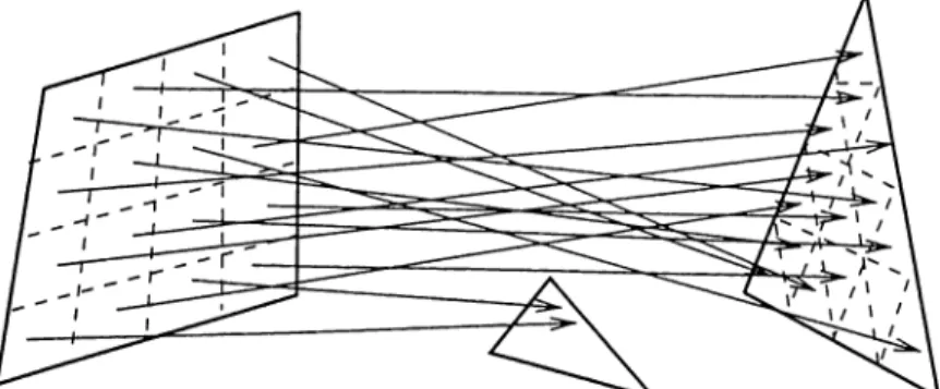
Solving this double area integral analytically is a complex and costly oper ation [She94]. In the next two sections two numerical methods for computing form factors will be discussed. The hemicube method [SH89] computes the form factors from a differential area to a finite area, whereas the ray-tracing method [WEH89] computes form factors from a finite area to a differential area.
CHAPTER 3. HIERARCHICAL RADIOSITY 20
• Due to energy conservation rule, sum of the form factors from a patch is equal to unity in an enclosed environment. Ei^ = 1
• Reciprocity principle Fij = Fji * Aj/Ai
• If the surface is convex, Fa = 0, i.e. a surface cannot absorb the light it emits, directly.
• Occlusion reduces the form factor of patches. For example, the form factor of invisible patches is 0. The effect of occlusion on form factor is shown in the formula ( Hij is the visibility factor).
coseiCos^ ^ ^ ^ d A ^ c iA ·
irr- (6)
Hem icube M ethod
In an attempt to calculate form factor, the hemicube method was introduced by Nusselt [SH89]. In this method, a half cube is placed onto the center of the source patch and all other patches are projected onto the faces of this cube. Each pixel is associated with one patch. If two patches are both projected onto the same pixel, the nearest one is associated with the pixel. This operation requires implementation of visibility tests, clipping, projection and z-buffering algorithms.
The form factor associated with a patch projected onto the hemicube is the sum of the form factors at all of the pixels associated with that patch. The
CHAPTER 3. HIERARCHICAL RADIOSITY 21
resulting form factors calculated with n hernicube give us a row ot the racliosity matrix.
Speed of the hemicube computation nuiy be dramatically accelerated if hard ware z-bufFering is available and scene is completely polygonal. In addition, due to functional similarity of rendering process and hemicube method, exist ing rendering code can be used for hemicube computation. A disadvantage of this method is that, it suffers from aliasing problems [She94].
Ray-tracing M ethods
These methods are based on firing sample rays between the two patches and av eraging their individual results. Two of them are disc approximation [WEH89] and Monte Carlo integration [CW93] methods. Disc approximation method as sumes the source patch as a disc and sufficiently far away from the destination patch. Only one ray is fired, and form factor is calculated. It is a cheap method but fails when the patches are near especially in corners. Analytical extensions are used for these cases. Monte Carlo integration method uses more I’ays and selects the points of these rays randomly. The result is an approximated value of form factor.
Curved surfaces can also be handled in ray-tracing methods. However the hemicube method is restricted to polygonal objects. Another advantage is that accuracy and speed can be controlled by changing the number of sample points.
3.1.2
Visibility Calculation
Visibility factor calculation is one of the most time consuming phases of ra- diosity process. Whatever the method we choose for the radiosity problem, we cannot avoid calculation of the visibility factor between all surfaces in a scene. This factor has an impact on the form factor value. Elimination of invisible parts of two patches decreases the form factor between them.
CHAPTER 3. HIERARCHICAL RADIOSiTY ·)■)
term. We obtain cin estimation of the term l)y firing a number of rays between two patches and counting the rays which do not intersect with another patcli. Clearly, accuracy can be adjusted by changing number of the sample rays. We can use common rays with form factor calculation. Note that hemicube method already includes visibility factor calculation inherently and does not need to recalcuhite this factor.
Some acceleration techniques have been suggested in order to speed up the ray tracing process ([Sam90b], [Sam90a]). These techniques are based on spatial subdivision of environment into cells. Spatial subdivision structures reduce the number of ray-surface intersection tests. The approach which must be followed during subdivision highly depends on the distribution of patches in the environment.
Although it is costly to detect occlusion, it decreases the number of interac tions which must be computed. Moreover, by exploiting visibility and spatial coherences, the cost of visibility factor computations can be significantly de creased.
Uniform subdivision
This method uniformly subdivides the space containing the environment into a grid of cells. These cells are equal sized and each keeps the list of objects contained in it. The main advantage of this type subdivision is that it lets fast traversal algorithms to be constructed to trace the path of a ray through the grid. Although it is very easy to built and maintain, it is inefficient for most cases. The distribution of objects in the environment must also be uniform to balance the object load of cells. Otherwise, due to unnecessary or insufficient divisions, performance loss can be observed.
Octree
Different from uniformly subdivision, this method aims to balance the object load of cells by adaptively subdividing. The whole environment is the root cell
CHAPTER 3. HIERARCHICAL RADIOSiTY ■2.·}
of the octree. Each cell is permitted to be subdivided uniformly into 8 cells if it contains more than some number of objects. Subdivision is performed re cursively. The resultant structure is a hierarchical tree of octree cells. Pointers to the objects can be kept at the relevant cell or only at the leaf cells.
During constructing octree, it is possible to have large cells that contain only a few small objects. Many rays may enter this region, which do not intersect the object. Although this increases the cost of trcicing path of ci. ray inside the octree, it is still an efficient model. It is easy to build and rmiintain an octree. Also fast traversal algorithms can be developed to trace path of rays.
The depth of octree is an important parameter for the performance. By changing the maximum number of objects that a cell can contain, the depth can be adjusted to get the highest performcince.
BSP tree
BSP tree (Binary Space Partitioning tree) method is the most efficient one among the listed methods, which aims to subdivide the space in the most economical way. Each cell is subdivided into 2 subparts by a separator plane each time. The decision of subdivision of a cell is given after finding the correct separator plane. The correctness criterion is leaving same amount of objects at each subparts. The resultant structure is non-uniformly sized cells, each with more or less same number of objects.
Although BSP tree is an efficient method, it tends to be more complicated to build and maintain, in contrast to the other methods. The traversal algorithms are also not as efficient as others. Another disadvantage of BSP tree is dividing the space into 2 parts. The depth of BSP tree may be three times bigger than the octree depth for the same scene.
CHAPTER 3. HIERARCHICAL RADIOSITY 24
3.1.3 The Ambient Term
In order to avoid getting ci dark eiiviroiiiuent at the early stages ol radiosity computation, an ambient term is added to the radiosity of cdl surfaces. Thus viewing initially dark environments becomes possible. As the radiosity solution converges, this term decreases. Ambient term has no effect on the solution process. It is used only for disphiying purposes.
3.2
Hierarchical Radiosity
Hierarchical radiosity is a method proposed to solve the radiosity problem [HSA91]. The idea used in hierarchical radiosity is borrowed from the N-body problem. In the N-body problem, each of the n particles in an environment exerts a force on all the other n - 1 particles in that environment, implying pairs of interactions. The fast algorithms which can compute all the forces in less than quadratic time are based on two key ideas;
• Numerical calculations are subject to error. Hence, results need only be calculated to within the given precision. •
• A group of bodies can be approximated by a single particle if they are positioned sufficiently far away from the body at which their force is being evaluated.
Radiosity and N-body problems share many similarities;
• There are lAlLAl pairs of interactions in both problems (without occlu sion).
• The fall off factor is ^ for both gravitational or electromagnetic forces and the magnitude of The form factor (/' is the distance between parti- cles/patches).
CHAPTER 3. HIERARCHICAL RADIOSITY 25
• According to the Newton’s third law, gravitational forces are equal and opposite, and, according to the reciprocity principle, form factors between two polygons are related.
• Polygons/bodies can have interaction with each other at different hierar chy levels.
However, certain differences do exist between the two algorithms. One of them is that the force of gravity is not effected by occlusion whereas for vis ibility calculations of radiosity problem occlusion is an important problem. Another difference exists during the process of hierarchy construction. N-body algorithms group particles together, whereas the radiosity algorithm subdivides initial polygons.
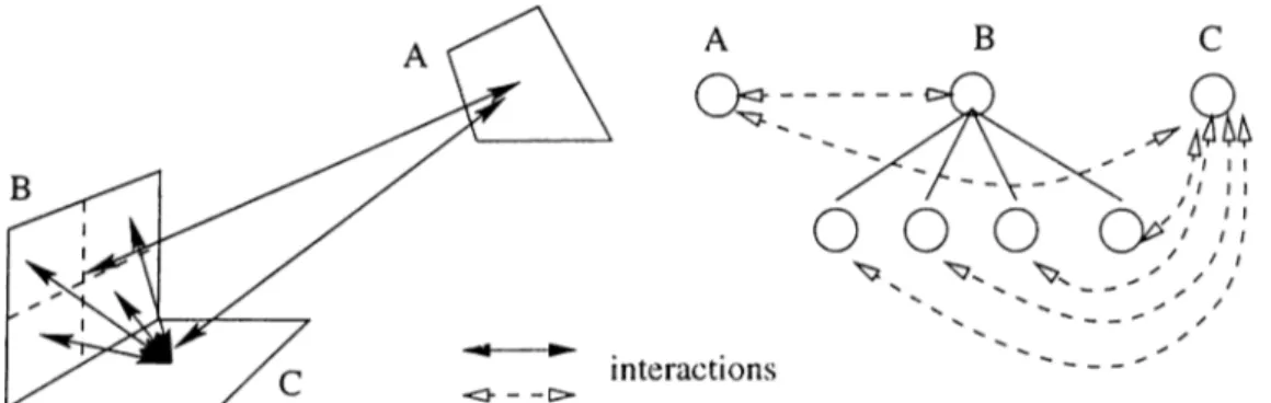
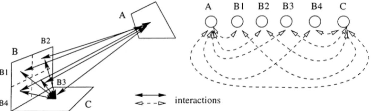
Figure 3.3 represents sample interactions at different hierarchy levels. Patch A is relatively far from patches B and C and so the radiant flux between itself and the other patches is low. Therefore, the error factor in evaluating the radiant flux will be negligible and the patch A is permitted interact with the patches B and C at the coarsest level.
However the patches B and C are near and the radiant flux among them is more than some threshold value. This makes the error factor in evaluating the flux considerably high enough to effect the accuracy of the flux value. In order to decrease the error factor, patch B is divided into subpatches and patch C is permitted to interact with the subpatches instead of B. As the surface area of patch B ’s subpatches is 1/4 of patch B, the flux will be lower. However, the flux may still be bigger than the threshold. In such cases, we should subdivide
CHAPTER 3. HIERARCHICAL RADIOSITY 26
the patches till the error factor becomes trivial.
3.2.1
Hierarchical Radiosity vs. Others
As mentioned before, radiosity method has costly operations which make it un usable even for simple scenes. To overcome this problem, different approaches have been proposed. Progressive radiosity and hierarchical radiosity is two of these methods which greatly speed up the computation of I'cidiosity.
Progressive radiosity is based on shooting light from the brightest surface to the environment, iteratively. Shooting is the process of distributing the light energy of a patch out to the rest of the environment. One iteration of progressive radiosity includes choosing the patch with the highest ‘ unshot’ light energy and shooting this energy to the other patches. Since most of the important energy transfers takes place within the first few iterations, useful results can be generated at the early stages of solution process. Also the matrix system converges faster than the conventional solution. Its another advantage is that storage is only 0 {N ) since configuration factors are discarded after they are used.
Figure 3.4 represents patch interactions in the same environment presented in Figure 3.3, which are created according to the progressive radiosity approach. The major drawback of progressive radiosity algorithm is its need of pre-meshed initial geometry. As a rule,_patches cannot be subdivided during the solution process. However, the rendering program recjuires small sized patches which do not carry important amount of energy so as not to cause visual artifacts in the
CHAPTER 3. HIERARCHICAL RADIOSITY 27
final image. This requires the patches forming the scene to be sufficiently sub divided into subpatches to a very fine resolution in cixlvance. Obviously this will cause too many initial patches and the algoritlim will waste time for handling trivial interactions of these trivial patcluis. Hierarchical rcidiosity algorithm has been developed just to overcome this problem. A hierarchical algorithm starts with undivided patches and subdivides them dynamically only when necessary. Therefore, hierarchical radiosity does not create or waste time with those trivial interactions. This can be observed in Figure 3.3 and Figure 3.4. Hierarchical radiosity creates 6 interactions whereas progressive radiosity cre ates 9 interactions. Time and space is saved by ignoring trivial interactions since the accuracy gained by computing them is negligible. As a result of this approach, we can say that hierarchical radiosity works most efficiently for the cases that initial patches are refined into large number of subpatches and less efficiently for the environments with complex initial geometry.
On the other hand, the hierarchical approach has storage problem. Each patch in the scene has to keep its own interaction list including pointers to other patches and configuration factors. This totally makes O(N^) cost. This is a very prohibitive factor for its usability, because even simple scenes can in clude more than a thousand patches after subdivisions. Fortunately clustering techniques ([SAG94], [Sil94], [SDS95]) overcome this problem by reducing the number of elements in interaction lists.
Due to its relative simplicity, progressive radiosity is probably the most implemented radiosity algorithm. Hierarchical radiosity is complex and still improving. Studies exist which combine the best sides of these techniques to get better results [HSD94].
CHAPTER 3. HIERARCHICAL RADIOSITY 2S
3.3
Design of An Object-Oriented Hierarchi
cal Radiosity Program
We designed and implemented an object-oriented sequential hierarchical ra diosity program in C-t--b language, and a simple polygon renderer program us ing OpenGL^ library. Some details of radiosity implementation are described below.
The program is mainly ba.sed on the algorithm presented in the paper [HSA91]. We used Gauss-Seidel iterative approach to solve the radiosity ec[uation (Ecjua- tion 1). Form factor and visibility factors are calculated using ray-tracing techniques. Different from our reference algorithm, we preferred to implement octree structure to speed up visibility calculations, instead of BSP -tree. It is easier and cheaper to implement an octree structure. In addition, hierarchi cal radiosity deals with relatively small amount of initial data and there is no memory problem for the tree structure. Also the overhead of BSP tree’s more complex traversal algorithms might bring extra costs.
This design has been implemented to ease our parallelization study. We tried to develop reusable and independent components as much as possible so as to be able to integrate them to our parallel model without a problem.
The model consists of the following objects and the main program:
• V ertex is a point in 3-dimensional space. REALTYPE x , y , z ;
Polygon is a convex planar geometric shape with 3 or 4 vertices. V ertex v e r t e x [ 4 ] ;
V ertex norm al; REALTYPE a rea ;
Patch is a Polygon associated with radiosity functions
CHAPTER 3. HIERARCHICAL· RADIOSITY 2!)
Polygon* p o ly g o n ;
P a tc h L is t* i n t e r a c t i o n L i s t ; REALTYPE B, E, rho;
Patch* p a re n t, * c h i l d [ 4 ] ;
• O ctree is a voxel expressed with only 2 vertices. V ertex v e r t e x [ 2 ] ;
O ctree* p a re n t, * c h i l d [ 8 ] ; P o ly g o n L ist* p o ly g o n L is t ;
• A lgorithm is the main program tiuit manages the objects and radiosity functions.
The V ertex, Polygon and O ctree objects are general purpose pbjects in dependent of the radiosity process. Polygons are surfaces of the objects in the environment. The Patch object is a Polygon associated with attributes and functions related with the radiosity process. These attributes are emissivity, reflectivity, and radiosity values, pointer to interaction list and quadtree point ers. Interaction list is a linked list to keep the pointers to the patches those are fully or partially visible by the list owner patch. Also, relevant information such as configuration factors is stored in this list. Quadtree pointers are used to maintain the hierarchy of patches. Root is always one of the initial patches and the rest of the tree is composed of subpatches of the root patch.
3.3.1
Algorithm of Hierarchical Radiosity
The program we built is based on the algorithm given in the paper [HSA91]. Basic steps of a hierarchical radiosity program;
1. B u ild in g e n v iro n m e n t read p oly g on s
in s e r t p o ly g o n s t o o c t r e e f o r a l l p o ly g o n s , p
f o r a l l o th e r p o ly g o n s , q i f p and q fa c e each oth e r
CHAPTER 3. HIERARCHICAL RADIOSITY 30
add both p olygon s to th e s e t o f in t e r a c t in g elem ents o f each o th e r
2. S o lv in g ra d io sity eq u a tion
w h ile r a d i o s i t y i s not converged f o r each p o ly g o n , p
g a th er ra d ia n ce o f p from i t s in t e r a c t in g p olygon s 3. R e n d e rin g p o ly g o n s
g a th e rin g ra d ia n ce, p
f o r a l l p oly gon s in p 's in t e r a c t io n l i s t , q
compute form f a c t o r and v i s i b i l i t y f a c t o r o f p and q i f refin em en t re q u ir e d
r e f i n e th e polygon w ith b ig g e r area update in t e r a c t io n l i s t s
e l s e add th e c o n t r ib u t io n o f polygon q t o r a d i o s i t y o f p (/*push and pull the radiosity*/)
i f p i s l e a f
add p 's em ittan ce t o r a d i o s i t y e ls e
g a th er ra d ia n ce from a l l c h ild r e n o f p , r e c u r s iv e ly
add t h e i r r a d i o s i t i e s to p 's r a d i o s i t y , w ith r e s p e c t t o t h e i r areas
Solving Radiosity Equation
As mentioned before, the radiosity equation (Equation 2) can be solved ef ficiently using iterative methods. In our program, vve selected Gauss-Seidel method to implement. An algorithm has been given in the previous section. It is physically equivalent to successively gathering incoming light. In each iteration of the algorithm, radiosity is gathered at each element and pushed down to its children. Once the leaves of the tree are reached, the element’s emittance is added, and the radiosities with respect to their areas are passed to upwards. An iteration for an element results by calculating its total radiosity