i Sı {to S' 'Iw'-iwîüi· '«■ · ■^•■^■¿■‘Ä 4K»f Ç; ÿ i ti 4 » .іЦіІ ^ ·ϊ*«. л ¡^шт 5'·$ Ş: tE’^Ş^a fíí .ÎÏÂ . ÿî; “ llŞk ,τ :ιρ>ί Μ '■« » ¡ ' w î іі 4«;-Ci? '*H|J·'· ib *Ä ii'r -î i ^ i i « i t 11·!?'?· д^*; :f*Ü**Í’ί'"ν· | : :ϊ. ■X ·*! -Mİ ·%ψ' ífcwí 1« Í ? ‘Ht ·(*!«* •"lir Яі 3¡; i:,-*- «í**·.,:
Л1 î î f » î ·: ^ ;v.i;:; „•T" .*іНг.-й îi Г?“-Лі Sîqî'i   l - İ Â i l ІІЦ:^''; ö''Wi№Â--Â4
. «íT^úiUí-.V Li ¿ С* W Âh· « ,ι'.ν V'"
‘t\/;iK :Â ÎÎx ÎiÎ~
REFLECTIONS O N ENVIRONMENTAL CONTROL:
LUMINOUS A N D SONIC ENVIRONMENTS
INSIDE THE DESIGN STUDIO
A THESIS
SUBMIHED TO THE DEPARTMENT OF
INTERIOR ARCHITECTURE A N D ENVIRONMENTAL DESIGN A N D THE INSTITUTE OF FINE ARTS
OF BİLKENT UNIVERSITY
IN PARTIAL FULFILLMENT OF THE REQUIREMENTS
FOR THE DEGREE OF
MASTER OF FINE ARTS
By
Ömer Önen
September, 1995
/ѴД 2?-Γ0
I certify that I have read this thesis and that in my opinion it is fully adequate, in scope and in quality, as a thesis for the degree of Master of Fine Arts.
Assoc. Prof. Dr. Cengjz Yeher (Supervisor)
I certify that I have read this thesis and that in my opinion it is fully adequate, in scope and in quality, as a thesis for the degree of Master of Fine Arts.
Prof. Dr. Mustafa Pultar
1 certify that I have read this thesis and that in my opinion it is fully adequate, in scope and in quality, as a thesis for the degree of Master of Fine Arts.
Asst. Prof. Dr. Nur Demirbilek
Approved by the Institute of Fine Arts
ABSTRACT
REFLECTIONS O N ENVIRONMENTAL CONTROL:
LUMINOUS A N D SONIC ENVIRONMENTS
INSIDE THE STUDIO
Ömer Önen
M.F.A in Interior Architecture and Environmental Design Supervisor: Assoc. Prof. Dr. Cengiz Yener
September, 1995
In this thesis, two environmental control parameters -lighting and acoustics- are studied. Since one of architecture's primary concerns is to provide human being's with comfort, emphasis is put on the approach that design decisions pertaining to lighting and acoustics should be considered in the earlier phases of the designing process. The design studio has been chosen since it houses many different functions simultaneously, with its significance as the place where design education actually begins. Accordingly, norms, numeric standards and common designing principles are compiled for design studios. Then, the lighting (luminance, illuminance) and acoustics (sound pressure level) performances of the design studios of the Dept, of Interior Architecture and Environmental Design, Faculty of Art, Design and Architecture of Bilkent University are measured. The results are, finally, evaluated and concluded with general technical advises for the amelioration of the measured studios.
Keywords: Environmental Control, Lighting, Luminance, Illuminance, Acoustics, Sound Pressure Level, Design Studio.
ÖZET
ÇEVRE DENETİMİ ÜZERİNE DÜŞÜNCELER:
TASARİM STÜDYOLARINDA
AYDİNLATAAA VE SES ORTAMLARİ
Ömer Önen
îç M im ari ve Çevre Tasarımı Bölümü Yüksek Lisans
Tez Danışmanı: Doç. Dr. Cengiz Yener Eylül, 1995
Bu tezde, çevre denetimi değişkenlerinden ikisi -aydınlatma ve akustik- çalışılmıştır. M imarinin öncelikli ilgi alanlarından birinin insanlara konfor sağlamak olduğu düşünülerek, aydınlatma ve akustiği ilgilendiren tasarım kararlarının, tasarım sürecinin erken aşamalarında ele akmasının gerekliliği vurgulanmıştır. Tasarım stüdyosu, bir çok farklı işlevi eşzamanlı olarak barındırdığı ve tasarım eğitiminin başladığı yer olduğu için seçilmiştir. Bunlara bağlı olarak, tasarım stüdyosunu ilgilendiren standartlar ve genel tasarım ilkeleri derlenmiştir. Bir sonraki aşamada, Bilkent U., G.S.T.M.F., İç M im ari ve Çevre Tasarımı Bölümü stüdyolarının aydınlatma (parlaklık, aydınlık) ve akustik (ses düzeyi) performansları ölçülmüştür. Sonuçta, ölçümlerden elde edilen bulgular değerlendirilmiş, performansları ölçülen stüdyoların iyileştirilmesi için önerilerde bulunulmuştur.
A nah tar Sözcükler: Çevre Denetimi, Aydınlatma, Parlaklık, Aydınlık, Akustik, Ses Düzeyi, Tasarım Stüdyosu.
M y deepest gratitude goes to M r. Cengiz Yener. W ithout his endless support and care, this thesis could have never been realized. His wisdom and knowledge in his field of studies is exceptional, as is his patience and assistance. I owe much of thesis to his unending patronage in all areas of education and his dedication to science.
In addition, I would like to thank Ayşıl Yavuz and Yıldırım Yavuz for their consistent interest and help throughout the development of the thesis. Their close attention played an important role in the finalization of the thesis.
ACKNOWLEDGMENTS
Finally, I would like to thank Mr. Mustafa Pultar, Mr. Türel Saranli, Mr. Önder Seren for their aid in the progress of the thesis; Miss Ebru Şahin and my family for their unforgettable collaboration during the two years of the Master's program at Bilkent.
TABLE OF CONTENTS
1 IN T R O D U C T IO N
1
1.1 Two Parameters of Environm ental C o n tro l... 4
1.2 M e th o d o lo g y ... 7
1.3 Form ... 1 2 2 O N LIGHT, SOUND A N D STUDIO 14 2.1 The Design Studio... 14
2.2 Design Studio Lighting... 17
2.3 Design Studio Acoustics... 26
3 THE MEASUREMENTS 31 3.1 D escription of the Studios... 31
3 .2 The Measurements ... 35
3 .2 .1 Luminance M easurem ents... 35
3 .2 .2 Illum inance M easurem ents... 5 0 3 .2 .3 Sound Pressure Level M easurem ents... 6 4 4 EVALU ATIO N 83 4.1 Luminous Environm ent... 83
4 .1 .1 Luminance M easurem ents... 83
4 .1 .2 Illum inance M easurem ents... 92
5 C O N C L U S IO N
no
5.1 G eneral C om m entary... 110 5 .2 Lighting C on clu sio n ... 115 5 .3 Acoustics C on clu sion... 120LIST OF REFERENCES
APPENDICES
123
LIST OF TABLES
T able 3 .2 .1 The Luminance Data ol· FCZ 23 (4th class) on M a y 2 9 th , 1 9 9 5 ... 38 T able 3 .2 .2 The Luminance Data of FA 2 1 4 -2 1 5 (1st class) on M a y 26 th, 1 9 9 5 ... 41 T able 3 .2 .3 The Luminance Data of FC 111 (3rd class) on M a y 2 5 th , 1 9 9 5 ... 4 4 T able 3 .2 .4 The Luminance Data of FA 3 1 7 -3 1 8 (2nd class)
on M a y 2 4 th , 19 95 4 7
T able 3 .2 .5 The Illum inance Data of FCZ 23 (4th class) on M a y 29 th, 1 9 9 5 ...5 4 Table 3 .2 .6 The Illum inance Data of FA 2 1 4 -2 1 5 (1st class)
on M a y 26 th, 1 9 9 5 5 6
Table 3 .2 .7 The Illum inance Data of FC 111 (3rd class) on M a y 2 5 th , 1 9 9 5 ... 5 9 Table 3 .2 .8 The Illum inance Data o f FA 3 1 7 -3 1 8 (2nd class)
on M a y 2 4 th , 19 95 62
Table 3 .2 .9 The Sound Pressure Level Data of FA 2 1 7 -2 1 8 (3rd class) on June 5th, 1 9 9 5 ... 6 7 T able 3 .2 .1 0 The Sound Pressure Level Data o f FCZ 23
(4th class) on June 1st, 1 9 9 5 ... 7 0 Table 3 .2 .1 1 The Sound Pressure Level Data of FCZ 23
(4th class) on M a y 29th, 1 9 9 5 ... 71
Table 3 .2 .1 2 The Sound Pressure Level Data o f FA 2 1 4 -2 1 5 (1st class) on M a y 26 th, 1 9 9 5 ... 75 T able 3 .2 .1 3 The Sound Pressure Level Data o f FC 111
(3rd class) on M a y 25 th, 1 9 9 5 ... 77 Table 3 .2 .1 4 The Sound Pressure Level Data o f FA 3 1 7 -3 1 8
(2nd class) on M a y 24 th, 1 9 9 5 ...80 T able 4 .1 .1 Recommended Luminances and C orresponding
Levels of H o rizo n ta l Illum inance...85 Table 4 .1 .2 Summary of the Luminance M easurem ents...87 Table 4 .1 .3 Illum inance C ategories and Ranges fo r Interior
Lighting D esign... 93 T able 4 . 1 . 4 Summary o f the Illum inance M easurem ents... 9 7 T able 4 .2 .2 N oise C rite ria fo r Rooms... 102 Table 4 .2 .3 Summary of the Sound Pressure Level
M easurem ents... 1 05 Table 4 . 2 . 4 Time vs. Background Sound Pressure Level... 106
LIST OF FIGURES
F igure 2 .2 .1 Luminance Relations between the Visual Task and S urrounding Surfaces... 20 F ig ure 2 .2 .2 Recommended Reflectances fo r Surfaces and
Furnishings in the Design S tu d io ...22 Figure 2 .2 .3 The A n g u la r Relationship of the W o rk Surface and the O ffe n d in g Z o ne... 23 Figure 3 .2 .1 The Luminance Data o f FCZ 23 (4th class) on M a y 2 9 th , 1 9 9 5 ... 39 Figure 3 .2 .2 The Luminance M easurem ents in FCZ 23
(4th class) on M a y 29th, 1 9 9 5 ...4 0 F igure 3 .2 .3 The Luminance Data of FA 2 1 4 -2 1 5 (1st class) on M a y 2 6 th , 1 9 9 5 ...42 F igure 3 .2 .4 The Luminance M easurem ents in FA 2 1 4 -2 1 5
(1st class) on M a y 26th, 1 9 9 5 ... 43 Figure 3 .2 .5 The Luminance Data of FC 111 (3rd class) on M a y 2 5 th , 1 9 9 5 ... 45 Figure 3 .2 .6 The Luminance M easurem ents in FC 111 (3rd class) on M a y 25th, 1 9 9 5 ...46 Figure 3 .2 .7 The Luminance Data of FA 3 1 7 -3 1 8 (2nd class) on M a y 2 4 th , 1 9 9 5 ... 48 F igure 3 .2 .8 The Luminance M easurem ents in FA 3 1 7 -3 1 8
Figure 3 .2 .9 The Illum inance Data of FCZ 2 3 (4th class) on M a y 2 9 th , 1 9 9 5 ... 5 4 F igure 3 .2 . 1 0 The Illum inance M easurem ents in FCZ 23
(4th class) on M a y 29th, 1 9 9 5 ... 55 Figure 3 .2 .1 1 The Illum inance Data o f FA 2 1 4 -2 1 5 (1st
class) on M a y 26 th, 1 9 9 5 ... 5 7 F igure 3 .2 .1 2 The Illum inance M easurem ents in FA 2 1 4 -2 1 5 (1st class) on M a y 26 th, 1 9 9 5 ... 58 Figure 3 .2 .1 3 The Illum inance Data of FC 111 (3rd class) on M a y 2 5 th , 1 9 9 5 ...59 Figure 3 .2 .1 4 The Illum inance M easurements in FC 111
(3rd class) on M a y 25th, 1 9 9 5 ... 6 0 Figure 3 .2 .1 5 The Illum inance Data of FA 3 1 7 -3 1 8 (2nd
class) on M a y 2 4 th , 1 9 9 5 ... 62 Figure 3 .2 .1 6 The Illum inance M easurements in FA 3 1 7 -3 1 8 (2nd class) on M a y 24 th, 1 9 9 5 ... 63 Figure 3 .2 . 1 7 The Sound Pressure Level Data o f FA 2 1 7 -2 1 8 (3rd class) on June 5th, 1 9 9 5 ... 68 Figure 3 .2 .1 8 The Sound Pressure Level M easurem ents in FA 2 1 7 -2 1 8 (3rd class) on June 5th, 1 9 9 5 ... 69 Figure 3 .2 .1 9 The Sound Pressure Level Data o f FCZ 23
(4th class) on June 1st, 1 9 9 5 ... 71 Figure 3 .2 .2 0 The Sound Pressure Level M easurements in FCZ 23 (4th class) on June 1st, 1 9 9 5 ... 72 Figure 3 .2 .2 1 The Sound Pressure Level Data of FCZ 23
(4th class) on M a y 29th, 1 9 9 5 ...73 F igure 3 .2 .2 2 The Sound Pressure Level M easurements in FCZ 23 (4th class) on M a y 29th, 1 9 9 5 ... 74
F igure 3 .2 .2 3 The Sound Pressure Level Data o f FA 2 1 4 -2 1 5 (1st class) on M a y 26th, 1 9 9 5 ... 76 F igure 3 .2 . 2 4 The Sound Pressure Level M easurements in FA 2 1 4 -2 1 5 (1st class) on M a y 26 th, 1 9 9 5 ... 78 Figure 3 .2 .2 5 The Sound Pressure Level Data of FC 111
(3rd class) on M a y 25th, 1 9 9 5 ... 7 7 F igure 3 .2 .2 6 The Sound Pressure Level Measurements in
FC 111 (3rd class) on M a y 25th, 1 9 9 5 ... 79 Figure 3 .2 .2 7 The Sound Pressure Level Data o f FA
3 1 7 -3 1 8 (2nd class) on M a y 24th, 1 9 9 5 ... 81 Figure 3 .2 .2 8 The Sound Pressure Level M easurements in
FA 3 1 7 -3 1 8 (2nd class) on M a y 24th, 1 9 9 5 ... 82 Figure 4 .1 .1 Recommended Scale of Luminance fo r Interiors... 86 Figure 4 .1 .2 A d d itio n a l Lighting fo r presentation b o a rd ... 86 Figure 4 .1 .3 M ean Luminance Values o f the Four Studios...91 Figure 4 . 1 . 4 M ean Illum inance Values o f the Four Studios... 9 9 Figure 4 .2 .1 N oise C rite ria C urves... 103 F igure 4 .2 .2 Time vs. Background Sound Pressure Level... 107 Figure 4 .2 .3 M ean Sound Pressure Level Values o f the Four S tudios... 1 09 Figure 5 .2 .1 Luminance - Illum inance Values o f FA 2 1 4 -2 1 5 (B ilkentl st)...115 Figure 5 .2 .2 Luminance - Illum inance Values of FCZ 23
(Bilkent4th)... 1 16 Figure 5 .2 .3 Luminance - Illum inance Values o f FC 111
(B ilke n t3 rd )...1 1 6 Figure 5 . 2 . 4 Luminance - Illum inance Values o f FA 3 1 7 -3 1 8 (Bilkent 2 n d )...1 17
1. INTRODUCTION
' On the error of those who practice without science. Those who fall in love with practice without science are like pilots who board a ship without rudder or compass, who are never certain where they are going.
Practice ought always to be built on sound theory.'
Leonardo da Vinci
The natural environment of the earth rarely provides its occupants
with satisfactory conditions for optimum development and well-being.
To overcome this obstacle, humans have built shelter; simply to
protect themselves, to alter the conditions of nature and satisfy their
psychological and physiological requirements at optimal levels.
Throughout history, building makers have developed various solutions
to the limitations introduced by local environmental conditions on
human comfort. In a slow pace of trial and error, indigenous
building types, with traditional solutions embodying the most suitable
material and form combinations, have emerged. The major concern
of architecture, accordingly, is to remove the gross environmental 1
load of nature from the shoulders of humans by forming man-made
environments Nvhere their sensory and behavioral conditions are
optimally comfortable. This is only possible if man-made shelters
function with environmental control mechanisms for protection from the
hostile or disruptive external environmental conditions, such as aiir
motion, noise, humidity, rain, electromagnetic radiation. O nly then
can humans maximize their capacities and focus their limited energy
upon performing those tasks and activities which are the essence of
the human experience.
Today, through rapid progress in building sciences, w ide ranges of
materials, products, forms, and solutions have become available.
During the twentieth century, great achievements have been
accomplished in the evolution of energy-consuming devices and
comfort-oriented environmental control mechanisms. However, as a
natural consequence of industrial and technological developments, more
complex environmental problems have arisen. These new
environmental problems -together with new environmental possibilities-
are to be dealt in accordance with new demands from building
As a result of this rapid growth, the role of the designer has
evolved. It is crucial for designers to understand the primary nature
of the relationship between the building and the natural environment,
since a building is the most important instrument used to modify it.
The topics a designer has to undertake have increased both iin
number and magnitude. For example, considerations of human
sensory response and behavior to the surrounding environmental
conditions have entered the domain of the designer. The breadth of
knowledge applicable to architecture has grown tremendously,
redefining architecture strictly as the group w ork of specialized
professionals. Progress has accelerated research. Fundamental
principles underlying new environmental phenomena are defined.
Guiding standards are set for the designers by governmental and
multinational research and development institutions. Methodology
patterns are established for solving common environmental design
problems inside the building.
At the outset of the thesis, it will be of good practice to clarify the
intended meaning of the word 'environment', as this will ease
understanding of the scope of the work. In the broadest sense,
the earth, on which all life forms exist. This definition, however, is
far too general for the projected extent of the study. Rather, the
environment and its relationship to humans is of particular interest.
In order to enhance understanding, the definition of the environment
should be limited to a ' momentary environment of one person in a
defined position or state, where he responds in some w ay to the
surrounding stimulus field ' (Szokolay 1). As the senses are
concerned, the physical limits of man's environment can hardly be
defined in exact terms, since stimuli arrive from a great range of
distances. However, in order to set the basis on which this study
w ill prosper, it is vital that certain limitations to the definition of
environment are stated. The following sections w ill seek to explain
the path on which the thesis w ill proceed.
1.1 Two Parameters of Environmental Control
It is necessary to consider two parameters of environmental control iin
the design process of buildings: Light and sound.
' Lighting design is considered to be the creative process to produce
of the built environment, utilizing available illumination engineering
technology' (Illumination Engineering Society, Application 1-1). It is
much more than just a building system; it is both an art and a
science. Lighting directly appeals to the senses, making it available
for humans to perceive the surroundings through the interaction of
light and shade. Bad lighting, alone, would be enough to mask
the aesthetic beauty of any architectural building or artwork.
Appearances of forms, colors, details, surfaces, textures and materials
would be unrecognized in the absence of designed lighting. As
again, the design decisions pertaining to natural and artificial lighting
should be considered in the earliest phases of the course of design.
Even though alterations can be made to the artificial lighting system
of a building after it has been completed, the decisions concerning
natural lighting should be dealt with in the beginning; for judgments
of w indow sizes, permanent shading devices, and building orientation
can hardly be modified after the construction of the building.
Moreover, ' without good lighting, we would waste billions of dollars
a year on salaries and benefits and ultimately on energy, spinning
our wheels' (Steffy x). This leaves the designer with the theoretical
and professional challenge of achieving high-quality environmental
and reasonable building and equipment costs. Again, it is the
concern of the responsible designer to conceptualize or visualize
lighted space and program his/her design accordingly. The sections
on lighting of this thesis will seek to address the programming issues
in lighting design applicable to design studios. Primary rule of
thumbs w ill be pointed out within an outline as to help the designer
to achieve successful lighting solutions. Numeric standards will be
indicated enabling the designer to realize basic calculations.
The foremost principle of architectural acoustics is to ' design for
good hearing and freedom from noise in and around buildings '
(Egan xv). This basic rule of acoustics have become an important
new tool for shaping the built environment. It is important for the
designer to realize the fact that diffusing the knowledge of acoustics
and to promote its creative applications in design is of utmost
significance for the success of his/her creation. ' Hopefully, not
only better acoustical environments, but also better buildings should
result ' (Egan xv). Acoustic requirements of a building should be
taken into consideration during the earliest stages of the designing
process. Although modifications can be made on the design later
usually demand radical changes in the shapes of spaces. Once the
building is constructed, it is very difficult to change shapes of
spaces, room heights, and other related design decisions such as
adjacencies to other spaces and buildings. Corrections in completed
spaces are very laborious and expensive. To avoid this, the
designer should understand the basic principles of acoustics. Thus, it
is the responsibility of the designer to arrange for flawless
relationships between spaces, shapes, volumes, adjacencies such that
their buildings behave acoustically efficient while effectively serving the
intended purpose for which they were constructed. It should be
remembered that the ' correct application of the principles of
architectural acoustics can considerably improve the quality of life at
work, during leisure time and in the home' (Ginn 8). The objective
of this argument is, therefore, to provide the designer with an
extensive background on classroom - design studio- acoustics through
compiling a set of fundamental concepts and definitions necessary for
understanding architectural acoustics.
1.2 M ethodology
study stands. Decisions which determine the path of research will
be explained in detail.
The bodies of knowledge of acoustics and illumination are very
principal to environmental control. Through years of research and
application, they have rightfully entered the realm of architectural
practice and constitute an inseparable portion of the framework of
intelligence which define architecture.
Architectural design, from a theoretical point of view, is a scenario.
The designing of any structure depends upon a conceptualization of
the events which are expected to take place within the structure.
The architect, as the scenarist, conceives of the spaces where these
events will occur, and through complex interactions of technical,
aesthetically, and cultural reflections, forms a setting for the intended
play. M any of the outcomes of architectural design are
straightforward or unconscious representations of these scenarios.
Among the many variables of architecture, there is one constant;
man. The whole architectural profession has one overruling motive;
From the point of interest of this research, the physical satisfaction
of man steps forward as the most determinant factor of
environmental control. In abstract terms, humans act as a meter of
satisfaction through their responses and judgments. W hat conditions
are suitable for or preferred by man can be established through
well-planned and executed studies. However, man as the experimental
subject, cannot provide the experimenter with precise measurements,
for he/she can only make comparative judgments. Moreover, ' if a
group of people is subject to the same environment, it will not be
possible, due to biological variance, to satisfy everyone at the same
time' (Fänger 13). Then, the aim of the designer should be to
create an optimally comfortable environment for the group; a
condition in which the highest possible percentage of the group is
in comfort.
Despite the subjectivity of man, it should be realized that one of
the purposes of this study is to understand the basic physical
needs of man, in terms of sound and light, in a functionally
predefined setting. The drive for limiting the research environment
has several justifications. As a result of the surplus of information on
driven to seek ways to apply the mass compilations of information
on a specific area, where there was a need for focusing. Due to
its rich functional definition, which w ill be outlined in the next
chapter, and its significance as the place where future designers are
to be educated, the design studio appeared to be the perfect choice to consider.
One might argue the isolation of a classroom from its surroundings,
as every system is a part of a larger system and that all systems
are, to some degree, connected to each other. The classroom is
surrounded by corridors and other classrooms; the faculty building is
adjacent to roads and other school buildings; the university is an
integral part of the texture of the city, with roads and building
complexes neighboring it. Thus, the activities taking place within a
classroom are, to a certain degree, a part of the universe, the
ultimate system. However, such a strict abstraction is arbitrary. For
research purposes, the isolation of a classroom from the rest of the
system can be justified as it can be said that the classroom has
measurable and controllable physical boundaries. This study,
therefore, carefully assesses the activities taking place within a
acoustical conditions.
The Faculty of Art, Design, and Architecture of Bilkent University is
formed of three adjoining buildings (see Appendix A) which forms a
monoblock structure, housing the departments of Interior Architecture
and Environmental Design, Graphic Design, Fine Arts, and Urban
Planning and Landscape Architecture. The faculty accommodates over 8 0 0 students in more than 3 0 design studios. W ithin this context,
the selection of the Faculty of Art, Design and Architecture as the
place for the measurements of design studios appeared as a correct
decision, since the buildings concerned are supposedly constructed
with the most up-to-date construction techniques and material choices
reflecting present-day design developments and contemporary
environmental concerns. W ithin the Faculty, the design studios of the
Department of Interior Architecture and Environmental Design are
selected. Ideally, one might think, that it would be more
appropriate to measure all the studios of the Faculty. However,
from a systematic standpoint, one will realize that limiting the number
of studios is a requirement of the scope of the intended study.
Moreover, one w ill discover in the following chapters of the thesis
of Interior Architecture and Environmental Design Building is carried
out, due to the fact that the floor plans of the building are
identical, with studios on top of each other, having similar physical
and social characteristics. Studios with unique characteristics are
also included in the study. Meanwhile, attention was shown to
include one studio from all four classes of the department program.
1.3 Form
The form of the thesis is analytical. The thesis starts out with an
introduction which, basically, aims to explain the principles on which
the study develops. The second chapter aims to decorate the
reader with in-depth explanations on the subjects pertaining to light
and sound inside the design studio, setting a general outline for the
technical scope of the parameters involved. The third chapter is
constituted of the light and sound measurements, descriptions of the
spaces from where and under which conditions they were taken, and
further comments on the outcomes of the measurements. The
conclusion chapter investigates the parameters of environmental control
both separately and as a total, while suggesting improvements where
the form of numeric data and charts, in order to enhance cognition
of the conditions of the studios measured. The appendices include
the 1 /2 0 0 plans of the three adjoining buildings of the Faculty of
Art, Design and Architecture, specifications of the apparatus used in
the measurements, and a glossary of definitions necessary for the understanding of the technical terminology used in the thesis.
2. O N LIGHT, SOUND A N D STUDIO
This chapter focuses on the functional analysis of a design studio,
the outlines of design studio lighting and design studio acoustics.
The primary concern of this chapter is to prepare the grounds on
which the measurements will follow and to set the basis for the
systematic evaluation of the conclusion chapter.
2.1 The Design Studio
The design studio in the school of architecture has an importance
far beyond that of simply learning course material. It is perhaps the
most intense and multidimensional 'classroom' experience in all of
higher education. In a very short time, 'the studio becomes the
matrix within which a student develops the habit of thinking and
talking both as a design professional and as a member of a team'
(Pressman 2). However, the philosophical significance of the design
studio is far too broad for the interests of this study. W hat is more
important is the definition of a design studio in terms of the
activities taking place in it. The recommended numerical quantities
for the environmental parameters involved in the vision of the thesis
can then be made.
The activities taking place in the studio can be classified in two
main categories: individual work and group work. The individual
tasks a design student accomplishes basically takes place on the
work surface assigned for each student. Namely, these tasks are
sketching, drafting, model making, reading and writing. Private
design critiques between a student and a teacher can also be
considered as an individual activity. Group w ork is very much alike
individual work. Although the work surface required demands more
space, this can be obtained through the effective arrangement of
individual w ork surfaces. (However, it should be mentioned that
and basic design considerations concerning the design studio
are not within the scope of this thesis.) Group works, in addition,
include activities such as inter-group meetings, class presentations,
design juries, lectures and exhibitions. As one might notice right
away, the activities inside the studio are diverse, which suggest a
challenge for the designer such that all the activities listed above
should find a place for themselves within the studio in harmony so interior
that both group and individual work can take place simultaneously,
without interrupting each other. Another point to consider in the
design studio is the duration of the working hours. M any
architectural education programs are similar in the sense that studios
occupy the longest weekly class hours. Accordingly, due to the
nature of architectural education and working habits, students are
expected to and do spend long hours in the design studio.
W herever administrations permit, the design studios are open twenty-
four hours a day - as is the case with many schools of
architecture. In this perspective, the use of the design studio day
and night requires a thorough investigation of the requirements of
lighting and acoustics.
Therefore, it is the purpose of this study to highlight the need for
different light and sound levels for the different activities, at different
times of the day taking place inside the studio. The following
sections aim at forming a general outline for the luminous and sonic
2 .2 Design Studio Lighting
Providing adequate lighting systems for design studio facilities will
require systematic planning from the outsets of the design process.
Actually, in all educational facilities lighting, the best results may be
expected when there is cooperation among designers, engineers and
administrators in the initial planning stage.
According to the Illumination Engineering Society of North America
(lESNA, Guide, 4), the project considerations for designing lighting
are summarized as economic considerations, energy, color,
reflectances, architecture, operation hours, use of the space, acoustics,
physical factors, dust and dirt, safety and emergency lighting ,
maintenance and codes. To begin with, the initial and life cycle
cost of the system constitute the economic considerations of lighting
design while the amount of energy consumed by and released from
the system -as heat- form the energy factor. Color temperature of
the light should coordinate with the color of the space. Color
rendering properties of lamps are important since colors should be
distinguished accurately in the design studio. High reflectances of
installation and vice versa. Size, shape, style, texture, and
orientation of the space -v/hich altogether belong to architecture-
effect the selection and placement of the luminaries together with the
hours of operation. Use of the space is the functional definition of
the studio, of the activities which w ill occur inside, their locations,
frequency and importance. In acoustical terms, it is expected that
the lighting system of the design studio should perform quiet
operation. This factor is determinant in the selection of the
luminaries. Physical factors such as vibrations, temperature, shock
and voltage variations affect the choice of the luminaries. Dust and
dirt, together with maintenance, are important in conserving the
efficiency of the luminaries installed. Safety of the occupants will
also be determined by the lighting levels mentioned in the codes.
Finally, the codes pertaining to lighting, which are to be specified iin
this and the fourth chapters, should be followed.
From the above listed project considerations for lighting design derive
general lighting criteria. These are illuminance levels, visibility, visual
comfort, luminances, color rendering and color temperature of the
lamps. The headings on illuminance and luminance levels are the
In determining the quantity of illumination necessary for any interior,
there are certain questions which need to be surveyed. lESNA
(G uide, 9) puts forward a set of questions to be considered, which
focus on the future occupants and activities of that particular space.
These questions are: ' W hat are the tasks; how much time and
what percentage of this time is spent on each task; how important
is each task, speed, accuracy; which tasks are visually most difficult,
most fatiguing; what are the occupants' ages ?'. The logic behind
surveying the teaching and administrative staffs as well as the
students is to obtain complete information for developing lighting
criteria.
After a careful consideration of the tasks involved, the need for
speed and accuracy, the ages of the observers, as well as other
factors, required illuminances can be determined. Since it is
uncommon for the design studio to contain only one visual task, a
thorough evaluation of the visual needs of each task should be
realized. Accordingly, a level of illumination should be defined for
each task and through a flexible lighting system with multilevel
controls, the user should be enabled to adjust the luminance level
It should be mentioned that providing the required quantity of
illuminance is of little value if the proper illumination quality is not
achieved. W hat is meant by the quality of illuminance is the ease
at which a visual task is performed - quickly and accurately-, while the visual environment is perceived as pleasing and comfortable.
The quality aspects of lighting embraces the considerations of
luminance, luminance ratios, light distribution, task specularity and
diffusion, surface reflectances, location of lighting equipment, color
and shadows. According to the IES JJgfiíing__ Handbook 1987
A p plication Volume (6-3), ' quality of illumination implies that all
luminances contribute favorably to visual performance, visual comfort,
ease of seeing, safety and aesthetics in relation of the visual tasks
involved'. Figure 2.2.1 below demonstrates the relationship between
the luminances of significant surfaces and the visual task.
-IIÍ4 L E S S T H A N 5 x T A S K L U M I N A N C E N O T L E S S T H A N 1 / 3 X ' Í M ^ T A S K L U M I N A N C E | N O T L E S S T H A N 1 / 3 x T A S K L U M I N A N C E T A S K L U M I N A N C E
Therefore, the luminance relationships of the various surfaces in the
studio should be designed within acceptable limits. As the eye
wanders from surface to surface, i.e. from the colored collage work
to the glossy whiteboard, it adapts from one luminance to another.
The luminances should be arranged so that the differences in
between surfaces do not create discomfort in the eye, due to the
elongation of adaptation time. Illumination Engineering Society (lES)
summarizes the rule of thumbs to be taken into consideration while
calculating luminance ratios within a space:
- In general, for good visual performance the luminance of any significant surface normally viewed directly should not be greater than five times the luminance of the task.
- No large area, regardless of its position in the room, should be less than one- third the luminance of the task.
- Surfaces immediately adjacent to the visual task should not exceed the
luminance of the task, but should be at least one-third the luminance of the task. - The difference in luminance between adjacent surfaces in the visual surround should be kept as low as possible (lES, ApplLcalion, 6-3).
Reflectances of the surfaces and finishings inside the design studio
play a significant role in the effectiveness of the designed lighting
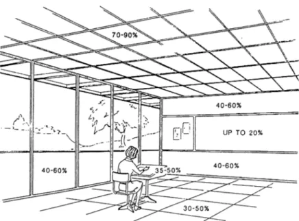
system. As can be seen, below, in Figure 2 .2 .2, the recommended
reflectances for surfaces and furnishings should be arranged together
interior and exterior luminances.
Figure 2.2.2 Recommended Reflectances for Surfaces and Furnishings in the Design Studio
Illuminances and luminances inside the design studio are very difficult
to obtain and require complex calculations and extensive study. The
balances reached as a result are very vulnerable to glare, as it will
produce excessively high luminances within the space. Glare can be
an end product of uncontrolled daylight and sunlight from windows,
high-luminance luminaries and specular surfaces and other sources.
The dimensions of all the parameters effecting the lighting design of
Numerous areas in schools need different lighting design solutions
due to their unique nature. The design studio, being the most
unique and complicated of all, demand high quality illumination since
discrimination of fine detail is frequently required for extended
periods of time. In addition, the instruments used for drafting, such
as hands, T-squares and triangles, obstruct the task and reduce
efficiency and visibility. Shadow's can be eliminated through the
selection of large luminous areas and overall ceiling lighting systems.
W hen these systems are not applicable, side illumination of the v/ork
surface should be considered. ' In such a system, the absence of
any luminaire in the offending zone also minimizes veiling reflections
and reflected glare' (lESNA, Guide, 21). Figure 2.2 .3 belov/ shows
the relationship of the offending zone to the angle of motion of the
w ork surface and the eye movements relative to the task surface.
A movable supplementary lighting equipment attached to the side of
the w ork surface w ill enable the student to position for critical task
requirements and to overcome shadows and reflections. Since the
appearance of colors in the studio become significant at times, the
selection of the color rendering properties of the light source
becomes important. ' Lamps with high color rendering capability
provide a more natural appearance of colors over a wide range -
even though they may be lower in efficacy. Light from the north
sky is often considered for such facilities' (lESNA , Guide, 20).
Displays and models will require directional concentrating sources for
improved visibility at a distance. Supplementary lighting from
adjustable luminaries can provide the model or display with a
definite directional light, at times emphasizing texture and glaze.
'An independent portable lighting system, separate from the general
lighting system and with some degree of flexibility with respect to
aiming and interchangeability of light sources, is often useful for
exhibitions' (lESNA, Q_uide, 21).
There are many possibilities concerning the decisions of design studio
lighting. Generally, the considerations are the determination of the
placement of luminaire(s), special area lighting decisions, lighting
controls, lighting for special activities and task/am bient lighting.
W ithin this general outline, the goal of educational facility lighting is
to provide an optimum visual environment for both the student and
2 .3 Design Studio Acoustics
W ithin the design studio, the basic expectations are short
reverberation time, low background noise, minimum flutter echo, ease
of conversation between individuals, groups and the whole class, high
intelligibility of words, low input noise from the surroundings and
flexibility in acoustical arrangements due to the functional adaptability
of the design studios.
Due to the nature of the designing process, a quiet ambiance free
from annoying sounds is usually expected. It should be mentioned
that ' noise heard in the form of unexpected loud sounds can
cause pronounced physiological effects- increase in heart rate, change
in breathing, even an increase in digestive activities' (Templeton and
Saunders 6). In this sense, according to Templeton and Saunders,
'the important factors which would appear to influence the subjective
disturbance due to sound are sound pressure level, duration of
exposure, evolution of sound event, frequency spectrum, sound
character, individual susceptibility, personal attitude to noise or sound
generator, mood of listener, state of health, and activity engaged
Egan lists the important criteria for room acoustics design as ' low
level of background noise, evenly distribution of sound energy
throughout the listening space, avoiding echoes and focusing effects,
sufficiently loud desired sounds and proper reverberation time characteristics' (170).
There are two main categories to be considered: The effective
absorption of sound within the studio and the effective isolation of
sound generated at the outside of the studio.
The intelligibility of speech plays a crucial role inside the design
studio. During individual, group, or class discussions, it is of utmost
importance that the intelligibility of words are at least satisfactory.
A disadvantage of the design studio from regular classrooms is that
it does not have a particular order of sitting, as in an auditorium.
Rather, the layout of the individual work surfaces are arranged as a
result of the social interactions between the students of the design
studio. Therefore, the source, path, receiver relationship can not be
constructed, making it difficult for the designer to conceptualize an
order for the walls of the design studio. W hen considering the
discussion, the reverberation time should be controlled around 0.75
seconds (Templeton and Saunders 134). The reverberation time
appears as 0 .8 seconds in Egan (88), with the indication that
longer reverberation times reduce the intelligibility of speech the same
w ay noise masks speech signals. The ceiling should be kept low
with sound-absorbing materials for controlling the buildup of noise
within the studio and made to act as a surface reflecting sound toward the other side, unless supplementary carpeted floors and
sound absorptive wall finishes are not provided. ' It is preferable
to place absorption on the side walls rather than on the ceilings'
(Egan 88), as this w ill prevent flutter echo. However, sound
absorbing materials should not be used on surfaces which should
provide useful sound reflections. When the design studio is used in
the classroom order and function, it is generally advised that ' the
distance between speaker and the rear of the classroom (design
studio) should be short so that loudness w ill be sufficient throughout
the room and the audience should have the ability to see the
person talking' (Egan 88) and in places where the distance from the
speaker to the farthest listener exceeds 10m. a speech reinforcement
sound system may be used. In addition to the reverberation time,
working areas should be aimed for, and that the background noise
level should not exceed the 38 dB limit' (68), for a higher
background noise level would mask speech intelligibility. Egan
indicates this number to be 34 dB (88). In open plans such as
the design studio, local screening and absorption play a particularly
important role in reduction of noise.
Another factor to be dealt with is the large w indow panes and
door openings particular to design studios. These huge openings
mean the intrusion of external noises, which should be controlled
through well-insulated window and door systems and building
orientation. Moreover, ' site features such as hills or slopes, earth
berms, thin-wall barriers, and nearby buildings to reduce intruding
environmental noise by interrupting the direct sound path (Egan 2 7 3)'
can be considered as an effective method of the isolation of sound.
Egan has prepared a checklist for the designer to consider for the
effective isolation of sound in any enclosed space. The headings of
the checklist are as follows:
- Select noise criteria for all activity spaces in buildings. Lay out rooms so sources of noise v/ill be located away from spaces requiring quiet or provide Insensitive buffer zones between to reduce transmitted airborne noise.
- Use sound-absorbing materials to reduce the buildup of noise levels in rooms and to muffle sound transmission through wall, plenum, or other cavities where sound absorption can contribute somewhat to sound isolation.
- Use heavy or double-layer constructions to achieve effective isolation, especially at low frequencies.
- Balance wall and ceiling constructions so that they will have nearly the same transmission losses.
- Seal all openings or cracks in building constructions because sound will travel through any opening regardless of its size. Sound leaks can greatly diminish the effectiveness of any sound-isolating construction (Egan, 273).
In the following chapters, among these outlines, the measurements on
acoustics will seek ways to come up with conclusions for the current
conditions of the design studios at the Department of Interior
Architecture and Environmental Design, at the Faculty of Art, Design;
3. THE MEASUREMENTS
3.1 Description o f the Studios
Before proceeding with the measurements on luminance, illuminance,
and sound pressure level, it appears to be necessary to give
explanatory physical information on the spatial characteristics of the
studios, since these w ill be of importance for the understanding of
the results.
The FA 2 1 4 -2 1 5 studio, as shown in the 1 /1 0 0 building plans
(Appendix B), is built facing south, overlooking the academic parking
lot of the Faculty, the new Architecture building site on the right ,
towards the continuation of the steep campus road, the dormitory
buildings of the University and in far distance, the construction of
the Bilkent-3 towers of Emiak Bank. On the north is a secondary
building. The west wall is adjacent to a computer laboratory, and
the east wall forms the corner of the east wall of the building, with
no openings on it. The FA 214-215 studio is also one of the
larger studios of the Faculty, crowded by the large number of
freshman students in the interior and a vast number of passerbys on
the outside.
The FA 2 1 7 -2 1 8 studio, as shown in the 1 /1 0 0 building plans
(Appendix B), is oriented to the east, facing a frequently used
high-steep campus road, the Emiak Bank III and Bilkent, Faculty of
Architecture construction sites nearby and a west sectional view of
Ankara. On the west of the studio is a main corridor of the FA
building, very frequently used by noisy passerbys, especially on June
5, 1995. On the north and south are two less frequently-used
corridors of secondary importance.
The FA 3 1 7 -3 1 8 studio, as shown in the 1 /1 0 0 building plans
(Appendix B), is looking to the east, right above the FA 217-218
studio. Therefore, since two studios are of exactly the same size,
shape and orientation, their physical characteristics are almost the
studio is, compared with the FA 217-218 studio, more distant to the
steep campus road, due to its elevation. Moreover, since this studilO
is on the top floor of the building, the traffic of the main corridor
on the west, and the two secondary corridors on the north and
south is much less crowded than the FA 217-218 studio.
The FCZ 23 studio, as shown in the 1 /1 0 0 building plans (Appendix B), is constructed looking north, to the Social Sciences
Building and a downhill garden through three self-standing, U-shaped
screen wails, ornamented by window openings. On the south, the
studio faces the entrance hall of the FC Building, a non-crowded,
moderately quiet area, occasionally occupied by groups on particular
events, such as exhibitions. On the west, behind the thick walls of
the building lies a garden, facing the campus' main pedestrian
w alkway axis. Finally, on the east, the building is elevated above
a garden adjacent to the steep campus road mentioned above. It
should be mentioned that the FCZ 23 studio is the largest studio of
the three faculty buildings.
The FC 111 studio, as shown in the Appendix B, 1 /1 0 0 building
of the Faculty buildings, below the construction site of the new
Architecture building, to the Food Center, Bookstore, and Gymnasium
on the far right, across the main pedestrian w alkway axis of the
University. On the north is a secondary corridor connecting to the
main corridor of the first floor of the FC building. However, since
this secondary corridor is also linking the FC and FB buildings, it is occasionally exposed to more frequent traffic. The west wall of the
studio is adjacent to another design studio, while the east wall is
shared with a very seldom used laboratory. The FC 111 is
3 .2 The Measurements
3 .2 .1 Luminance M easurements
The luminance measurements were recorded between M a y 23- M ay
29. The measuring process took place at the Department of
Interior Architecture and Environmental Design; Faculty of Art,
Design, and Architecture of Bilkent University, Ankara, in the 1st, 2nd, 3rd, and 4th class design studios' final juries of the
academ ic year 1 9 9 4 -1 9 9 5 . Detailed information on the process
are given on the recorded data tables (3.2.1 to 3.2 .4 ), figures
(3.2.1 to 3 .2 .8 ) and related paragraphs.
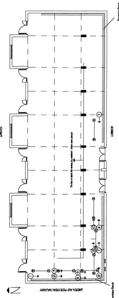
The measurements were taken in the FCZ 2 3 , FA 21 4 -2 1 5 , FC
111, and FA 3 1 7 -3 1 8 studios. Plans of these studios and the
exact locations of where the measurements were taken are given
Equipm ent Used
The equipm ent used for obtaining luminance data was the M inolta
Luminance M eter LS-lOO and necessary accessories. Further
information regarding the specifications of the apparatus is given
in A ppe nd ix A. Settings Unit; C .C .F./LU M L: PEAK/C O N T.; C alibration: Measuring M ode; Response; cd /m ^ none Continuous Preset ABS. Fast M e th o d o lo g y
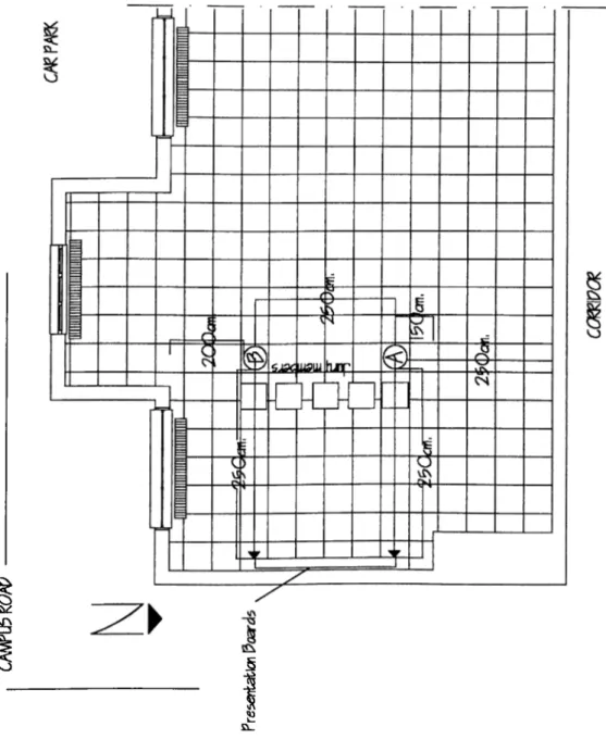
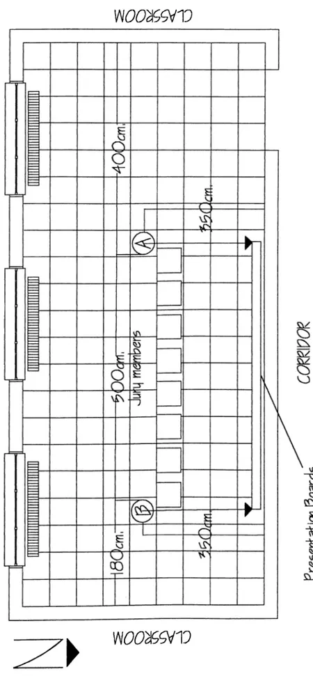
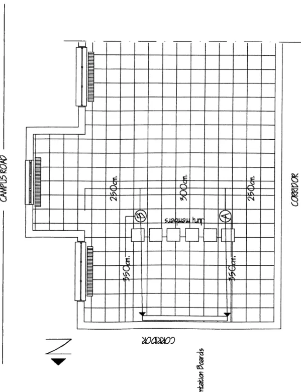
The luminance measurements aimed at recording the amount of
light that reflected from the surfaces of the presentation boards ,
The objective behind this experiment was to observe how the jury
members, the student presenting h is/h e r work, and the students
w atching the jury were affected by the amount of light reflected
from the presentation boards. As shown on the corresponding
figures 3 .2 .2 , 3 .2 .4 , 3 .2 .6 , 3 .2 .8 , the luminance meter was
placed in two adjacent points, equally distant from the w all,
facing the presentation board. The first point was chosen on the
far left part of the board while the other being placed on the
far right section, in order to have a broader information on the
distribution of the reflecting light. Thus, the instrument was
capable of recording, in 30-minute intervals, the luminance value
(in cd/m ^) at the exact location where the jury was being held. A ccordingly, it was possible to infer, from the recorded luminance
values, whether the occupants mentioned were able to see the visual task w ith ease and accuracy or not.
Notes on the Recorded Data
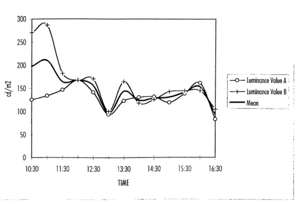
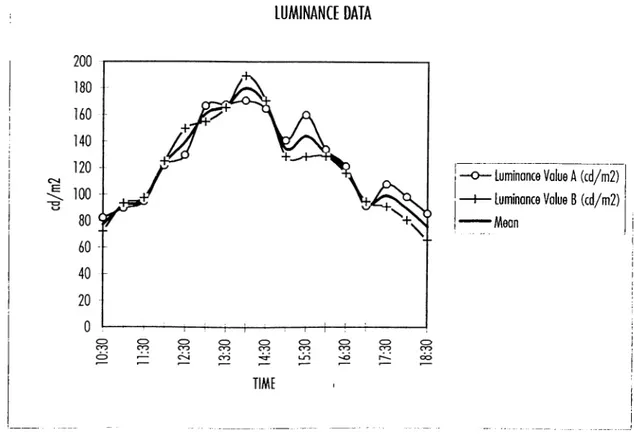
M a y 2 9 , 1 9 9 5 (FCZ 23): On this pa rtia lly cloudy day, eleven
measurements were taken between 1 1 :0 0 and 1 6 :3 0 hours, at 30
3 .2 .1 . The lowest A and B luminance measurements were taken
at 1 2 :3 0 , respectively as 3 1 .9 cd /m ^ and 2 8 .7 cd/m ^.
S am ple Num ber Time Luminance Value A ( c d /m 2 ) Luminance V alue B ( c d /m 2 ) Mean
1 11:20 66.79 137.4 102.1 2 11:50 80.80 47.74 64.27 3 12:20 73.30 60.87 67.09 4 12:50 78.97 74.70 76.84 5 13:20 73.53 74.51 74.02 6 13:50 71.62 77.84 74.73 7 14:20 100.9 74.71 87.81 8 14:50 118.2 94.33 106.3 9 15:20 83.60 82.29 82.95 10 15:50 76.47 77.60 77.04 11 16:20 80.8 79.83 80.32
Table 3.2.1 The Luminance Data of FCZ 23 (4th class) on M ay 29th, 1995
However, these values do not appear in table 3 .2 .1 , due to the
fact that at that exact moment, as a result of a steady decline
in the luminance, the jury members felt the need to turn on the
florescent lights. From this time on, the values are recorded
under da ylig ht as well as supplementary artificia l lighting.
Actually, the highest A value of the day was reached under this
com bination, as 118.2 cd /m ^ at 1 4 :5 0 and the peak B value as
1 3 7 .4 c d /m ^ at 1 1 :10 , recorded at the far north-west end of the
studio, under partial morning sunlight exposure. Finally, the daily
only, a long façade looking north, with three projections towards
the garden, with no openings on the west, east or south.
LUMINANCE DATA 140 1 0 4 E 60 -□ Luminance Value Д (cd/m2) Б1 Luminance Value В (cd/m2) □ Mean TIME
Figure 3.2.1 The Luminance Data of FCZ 23 (4th class) on M ay 29th, 1995
M a y 2 6 , 1 9 9 5 (FA 2 1 4 -2 1 5 ): On this dom inantly shiny -but
sometimes p a rtia lly cloudy- day, thirteen measurements were
recorded between 1 0 :3 0 and 1 6 :3 0 hours, at 3 0 min. intervals.
During the whole time, no lights were turned on by the jury
members in this studio facing south. The jury was held on the
far south-east corner of the studio; making clear the relatively high
morning values of B. The lowest values were 8 3 .6 cd /m ^ for A
at 1 6 :3 0 and 100.8 cd /m ^ for В at 1 3 :0 0 hours. The
J
T h e h ig h e s t v a lu e s , o n th e o t h e r h a n d , w e r e r e c o r d e d a t 1 1 ; 0 0
a . m . f o r B a s 2 8 6 . 8 c d / m ^ , a n d 1 6 7 . 6 c d / m ^ a t 1 2 : 0 0 n o o n
f o r B ; b o t h in th e m o r n in g w h e n th e s u n e n t e r e d th e s t u d io
t h r o u g h th e la r g e w i n d o w p a n e s o n th e f a r s o u th - e a s t w a ll.
Sample Number Time Luminance Value A (cd/m2) Luminance Value B (cd/m2) Mean
1 10:30 125.5 270.3 197.90 2 11:00 133.7 286.8 210.25 3 11:30 146.7 182.4 164.55 4 12:00 167.8 167.6 167.70 5 12:30 141.7 171.0 156.35 6 13:00 93.77 100.8 97.29 7 13:30 123.5 165.3 144.40 8 14:00 130.9 118.3 124.60 9 14:30 132.7 126.0 129.35 10 15:00 119.9 143.4 131.65 11 15:30 139.3 145.3 142.30 12 16:00 162.6 145.7 154.15 13 16:30 83.62 105.1 94.36
LUMINANCE DATA
г···
• Luminance Value A i i ■ Luminance Value B ‘ ■
■Mean , I
Figure 3 .2.3 The Luminance Data of FA 214-215 (Is t ciass) on M ay 26th, 1995
M a y 2 5 , 1 9 9 5 (FC 111): On a completely open and sunny
sky, seventeen measurements were recorded between 1 0 :30 and
1 8 :3 0 at 3 0 min. intervals. This studio is also looking only to
the south, with the jury located on the north w all, explaining why
the В values were higher in the morning w hile the A values took
control in the afternoon, starting at 1 5 :0 0 hours. The highest
values of the day were 170.6 cd /m ^ for A and 1 8 9 .4 cd/m ^
for B, both at 1 4 :0 0 noon. The lowest value for A, which was
on the western side of the studio, was 82.1 c d /m ^ at 10:30
I
s
£ Si_
In this studio, 6 6 .3 c d /m ^ had been the lowest B value at
1 8 :3 0 , for B which was located on the eastern part of the
studio. However, since the FB building's western w all was
blocking the eastern morning sun of the studio, the morning luminance was lower than expected for B. W hen the sun rose
rays into the studio at 1 4 :0 0 , the val
enough to send its ues
reached their clim ax for the day. Finally, the d a ily averages for A and B were 125.2 and 120.8 c d /m ^ respectively. N o lights
were turned on in this studio throughout the day.
S am ple Num ber Time Luminance Value A ( c d /m 2 ) Luminance V alue B ( c d /m 2 ) Mean
1 10:30 82.13 72.16 77.15 2 11:00 89.16 93.11 91.14 3 11:30 94.45 97.04 95.75 4 12:00 121.6 124.9 123.3 5 12:30 129.6 149.5 139.6 6 13:00 166.5 154.7 160.6 7 13:30 167.6 165.4 166.5 8 14:00 170.6 189.4 180.0 9 14:30 164.5 170.5 167.5 10 15:00 140.8 128.9 134.9 11 15:30 160.0 128.7 144.4 12 16:00 134.3 129.1 131.7 13 16:30 121.8 116.5 119.2 14 17:00 91.68 95.31 93.50 15 17:30 108.2 91.32 99.76 16 18:00 98.87 81.36 90.12 17 18:30 86.20 66.34 76.27
LUMINANCE DATA
■ Luminance Volue A (cd/m2) ■ Luminance Value B (cd/m2) •Mean
Figure 3 .2 .5 The Luminance Data of FC 111 (3rd class) on M ay 25th, 1995
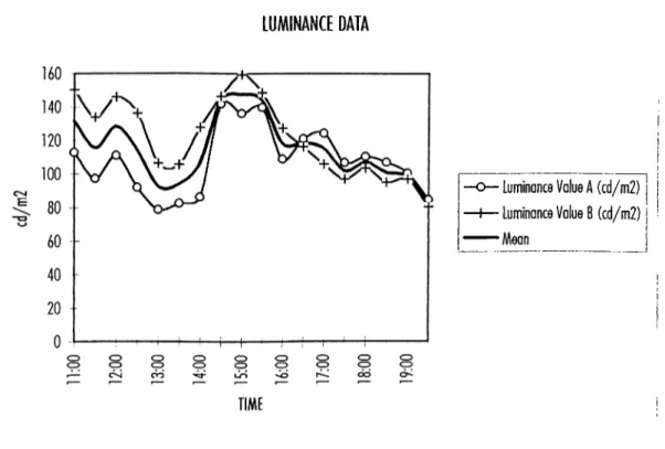
M a y 2 4 , 1 9 9 5 (FA 3 1 7 -3 1 8 ); On a partly cloudy, otherwise
sunny day, eighteen measurements were recorded between 1 1:00
and 1 9 :30 , at 3 0 min. intervals. It should be remembered that
this studio was facing east, the jury being held on the far north
western section of the studio, with the A measurement point
located on the western side of the studio and the B placed
nearer to the eastern part. As the sun rose to the top of the
building, a constant decline in the luminance values could be
observed. As a result, at 14:30, the jury members decided to
I
o o
W 0^9iV
T h is a c t io n c a u s e d a r e c o g n i z a b l e s h ift in th e lu m in a n c e le v e l, w h ic h a lm o s t im m e d ia t e ly e n t e r e d a n o t h e r d e c l in in g p h a s e a s th e s u n m o v e d f r o m e a s t to w e s t. T h e m in im u m v a lu e s f o r A a n d B w e r e 7 8 . 7 c d / m ^ a n d 8 0 . 8 c d / m ^ r e s p e c t iv e ly . T h e a v e r a g e s w e r e c a lc u la t e d a s 1 0 8 . 0 6 c d / m ^ f o r A a n d 1 2 1 . 4 c d / m ^ f o r B. F in a lly , th e m a x im u m s r e a c h e d 1 3 9 . 8 c d / m ^ f o r A a n d 1 5 0 . 3 c d / m ^ f o r th e B m e a s u r e m e n t p o in t .
Sam ple Num ber Time Luminonce Value A ( c d /m 2 ) Lum inance Value B ( c d /m 2 ) M ean
1 11:00 112.9 150.3 131.6 2 11:30 97.13 133.7 115.4 3 12:00 111.0 145.9 128.5 4 12:30 91.88 136.3 114.1 5 13:00 78.74 106.4 92.57 6 13:30 82.64 105.7 94.17 7 14:00 86.46 127.8 107.1 8 14:30 141.9 146.5 144.2 9 15:00 136.1 159.3 147.7 10 15:30 139.8 148.5 144.2 11 16:00 109.1 127.5 118.3 12 16:30 121.1 116.4 118.8 13 17:00 124.6 106.2 115.4 14 17:30 107.2 97.43 102.3 15 18:00 110.8 103.9 107.4 16 18:30 107.4 95.51 101.5 17 19:00 101.0 97.30 99.15 18 19:30 85.29 80.84 83.07
LUMINANCE DATA
■ Luminance Value A (cd/m2) • Luminance Value B (cd/m2) “Mean
vr\ o vn “ J3 S £!l.
Figure 3.2.8 The Luminance Measurements in FA 317-318 (2nd class) on May 24th, 1995
3.2.2. Illuminance Measurements
The measurements were recorded between M ay 23- M ay 29. The
measuring process took place at the Department of Interior
Architecture and Environmental Design; Faculty of Art, Design, and
Architecture of Bilkent University, Ankara, in the 1st, 2nd, 3rd, and
4th class design studios' final juries of the academic year 1994- 1995. Detailed information on the process are included on the
recorded data tables (3.2.5 to 3.2.8), figures (3.2.9 to 3.2.16) and
related paragraphs.
The illuminance measurements were taken in the FCZ 23-24, FA
214-215, FC 111, and FA 317-318 studios. Plans of these studios
and the exact locations of where the measurements were taken are
Equipment Used
The equipment used for obtaining illuminance data was the Minolta
Illuminance Meter and necessary accessories. Further information
regarding the specifications of the apparatus are supplied iin Appendix A.
Settings
Unit: lx
Response; Fast
N orm ./St. Dev.: Norm.
A U T O /M A N U .; AUTO
M ethodology
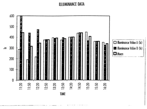
The illuminance measurements aimed at recording the amount of
ambient light which was present in the design studios, where design
projects were presented during design juries. The aim behind this
experiment was to observe how the jury members, the student