The Production Guide for the
Zarqaliyya (Universal Astrolabe) in the
Work of Abu al-Hasan al-Marrakushi
Atilla Bir*
Saliha Bütün**
Mustafa Kaçar***
Âdem Akın****
Abstract: One of the greatest astronomers of the 13th century, Abū ʿAlī al-Ḥasan al-Marrākushī is the
author of Jāmiʿ al-mabādī’ wa-l-ghāyāt fī ʿilm al-mīqāt (An A to Z of Astronomical Timekeeping) which includes the production and operation guides for many astronomical instruments. This study translates the production guide Zarqāliyya, examines the working principle of this instrument, and presents a mathematical interpretation for current readers. A standard astrolabe provides measurements by means of disks produced separately for the different latitudes. The particular disk we examine in this article was developed by the Andalusian astronomer al-Zarqālī (d. 493/1100), is named zarqāliyya, and is known as ṣafīḥa in the West. This disk is peculiar to Islamic astronomy and enables measurement for any latitude. At present, this astrolabe is qualified as universal for being operational independent of latitude. Marrākushī’s discussion of this universal disk zarqāliyya in his time is an epitome for the understanding of the transmission and circulation of knowledge in the scientific environment of Islam, and the current article evaluates this aspect. This article includes the subject and importance of Marrākushī’s monumental work, its modern presentations, and the mathematical explanations of the universal astrolabe’s stereographic projection. It additionally provides the formulations necessary for constructing this astrolabe and presents drawings based on these relations using the Paris edition of the manuscript registered as Or. No.2507-2508 in the National Library of France. The stars and coptic months engraved on the instruments are presented as tables. Lastly, this study includes an annotated translation by comparing the different editions of the manuscript.
Keywords: Marrākushī, Zarqālī, zarqāliyya, astrolabe, ʿilm al-mīqāt, ṣafīḥa, universal disk, astronomical
instruments
Bir, Atilla. Bütün, Saliha. Kaçar, Mustafa. Akın, Âdem. “The Production Guide for the Zarqaliyya (Universal Astrolabe) in the Work of Abu al-Hasan al-Marrakushi”, Atıf©
dx.doi.org/10.12658/Nazariyat.6.1.M0089en DOI
Translated by Beyza Akatürk***** and Sena Aydın******
* Prof. Dr., Fatih Sultan Mehmet Vakıf University, Faculty of Literature, Department of the History of Science. Correspondence: [email protected]. ** PhD Student, Fatih Sultan Mehmet Vakıf University, Faculty of Literature, Department of the History of Science. Correspondence: salihabudak.
*** Prof. Dr., Fatih Sultan Mehmet Vakıf University, Faculty of Literature, Department of the History of Science. Correspondence: [email protected]. **** Assist. Prof., Fatih Sultan Mehmet Vakıf University, Faculty of Literature, Department of the History of Science. Correspondence: [email protected]. ***** Translator.
***** PhD Candidate, Istanbul Medeniyet Universtiy, Department of Philosophy.
Introduction
I
slamic astronomers have designed various instruments1 for generatingsolutions to the problem of calculating time and location. Astrolabes are among these instruments and are often identified with Islamic astronomy; they are the objects that give insights into the mathematical level of its times for modern readers. Astrolabes provide us with information about the scientific craft and perspectives on the astronomical subjects of the period.
Julio Samsó, a historian of Islamic sciences, considers the astronomical tools in the Andalusian style to be an original and advanced demonstration of the high knowledge in the field of theoretical astronomy. The tool that can be classified as the universal disc, universal astrolabe disc, or universal astrolabe and is known in the West as saphea Azarchelis, or simply saphaea (ṣafīḥa), is one of these. The universal disc, which is a special type of astrolabe that allows measurements at any latitude and is one of the first examples inspiring the development of later universal astrolabes, was designed by the Andalusian astronomer Abū Isḥāq Ibrāhīm ibn Yaḥyā al-Naqqāsh al-Zarqālī2 (d. 493/1100) in the 11th century. Al-Zarqālī, who called this disc of his own invention the zarqāliyya, produced two different universal disks: the zarqāliyya and the slightly more simplified model, the shakkāziyya. This tool was first used in Andalusia and wasn’t understood or become widespread to the Latin Christian world until Zarqālī’s works were translated by Jacob Ibn Tibbon3 (d. 1305) in 1263.4
This tool, unrequited in the Eastern Islamic geography, was seen peculiar to the Andalusia and Maghreb regions. Abū al-Ḥasan al-Marrākushī (d. 680/1281), another important astronomer of that time, was known to be active in Cairo in the 13th century and was also aware of Zarqālī’s invention. He wrote the most comprehensive and successful encyclopedic work, Jāmiʿ al-mabādī wa-l-ghāyāt fī
ʿilm al-mīqāt (An A to Z of Astronomical Timekeeping), which was used for centuries
as a reference for astronomical instruments in the Islamic scientific environment.
1 Julio Samsó, Islamic Astronomy and Medieval Spain (London: Variorum, 1994), 9.
2 Roser Puig, “al-Zarqālī”, in The Biographical Encyclopedia of Astronomers (BEA), ed. Thomas Hockey (New York: Springer, 2007), 1258–60.
3 Raymond Mercier, “Jacob ben Makhir ibn Tibbon”, in The Biographical Encyclopedia of Astronomers
(BEA), ed. Thomas Hockey (New York: Springer, 2007), 538.
4 John D. North, Cosmos: An Illustrated History of Astronomy and Cosmology (Chicago: University of Chi-cago, 2008), 221.
Part III of this work includes the construction of the zarqāliyya and Part IV contains the user manual.5
This article only discusses the production guide of the zarqāliyya; the section related to its usage will be examined in another article. The text has been translated from Arabic, and the calculations in the text are interpreted in consideration of the current mathematical literature.
I. Life and Work
Sharaf al-Dīn Abū ʿAlī al-Ḥasan ibn ʿAlī ibn ʿUmar al-Marrākushī,6 one of the most important astronomers to live in Cairo in the 13th century, must have been from Marrakech,7 as can be understood from his surname. Because his name is not found in any biographical or bibliographical books, the information about his life is based on his work, Jāmiʿ al-mabādī wa-l-ghāyāt fī ʿilm al-mīqāt which is thought to have been written in Egypt between 1276 and 1282 based on information provided by Najm al-Dīn Abū ʿAbd Allāh al-Miṣrī. Based on al-Miṣrī’s writings, we can say that Marrākushī was probably in Cairo between 1281 and 1320.8
The time interval that we accept Marrākushī to have spent in Cairo (during the Mamluk era) corresponds with the time that the office of the muwaqqit was in operation. The office was established during the reign of the Mamluk Sultan Qalawun I for fulfilling the demands of the mosque administration, of the muazzins and muwaqqits, as well as of the toolmakers and other related subjects and coterie members of Egyptian society. In this period, when muwaqqits were employed in mosques and their profession was formed and ʿilm al-mīqāt had become a branch of astronomy beyond just time calculation, Marrākushī’s work provided the opportunity to consolidate the foundations of this tradition, and his work became a basic resource.9
5 In his work’s Introduction, Marrākushī states that he collected information about the astronomical tools that he could find, made additions and corrections to them, and also included some tools of his own invention. François Charette, Mathematical Instrumentation in Fourteenth-Century Egypt and Syria:
The Illustrated Treatise of Najm al-Dīn al-Miṣrī (Boston: Brill, 2003), 739.
6 Heinrich Suter, Die Mathematiker und Astronomen der Araber und ihre Werke (Amsterdam: Oriental Press, 1981), 144.
7 David A. King, “The Astronomy of the Mamluks,” ISIS 74, no. 4 (1983): 539.
8 F. Charette, “Marrākushī: Sharaf al-Dīn Abū ‘Alī al-Hasan ibn ‘Alī ibn ‘Umar al-Marrākushī”, in The
Bi-ographical Encyclopedia of Astronomers (BEA), ed. Thomas Hockey (New York: Springer, 2007), 739–40.
9 Taha Yasin Arslan, “Merrâküşî”, in İslam Düşünce Atlası, ed. İbrahim Halil Üçer (Konya: Büyükşehir Belediyesi Kültür A.Ş., 2017), 773.
Although the author of the work states in the Introduction that it had been written due to toolmakers’ insufficient training and methods they used, it gives the impression that the audience it addressed were clearly expert muwaqqits and their assistants who were in charge of time calculations. Because the book requires a high level of technical knowledge, the reader is required to have sufficient knowledge of arithmetic, geometry, spherical trigonometry, and algebra.10
David A. King, who has conducted extensive research on Mamluk astronomy, evaluates Marrākushī’s work as one of the two most comprehensive works and as the most successful one written aboutinstrument making in Islamic civilization prior to and during the time that Marrākushī lived.11 King emphasizes this work, which contains many astronomical tables, spherical trigonometry examinations, and applications of the use of various tools, to be unique in Islamic astronomy.12
Marrākushī recorded 44 of the 135 locations exclusively in red ink in the geographic location chart of the work. These locations cover an area that start on the Atlantic coast of today’s Western Sahara; extend to the Andalusian cities of Seville and Cádiz; continue on to Algeria, Tunisia, and Tripoli along the Mediterranean coast of North Africa; and reach to Alexandria, Minya, and Cairo. The use of red ink can be interpreted as his having personally visited these locations and obtained some of the geographical latitudes in his mathematical calculations through his own observations.13
Marrākushī is known to have written only one treatise, which contains two volumes and four books. The first book is about calculations and contains 87 chapters.14 This book covers detailed calculation methods related to chronology, trigonometry, geography, spherical astronomy, prayer times, solar movements, fixed stars, and sundials without covering proofs. The second book is on instrument making and contains seven chapters. The first chapter is on graphical methods in spherical astronomy and sundials. Chapters 2 through 7 cover the construction
10 Marrākushī, Jāmiʿ al-mabādī wa-l-ghāyāt fī ʿilm al-mīqāt, Topkapı Palace Library, Ahmet III Collection,
MS 3343, ff. 2a–2b.
11 David A. King, In Synchrony with the Heavens: Studies in Astronomical Timekeeping and Instrumentation in
Medieval Islamic Civilization II: Instruments of Mass Calculation (Leiden: Brill, 2005), 13.
12 King, “The Astronomy of the Mamluks,” 539. 13 Charette, Mathematical Instrumentation, 10.
14 Al-Marrākushī, Jāmiʿ al-mabādī, f. 2b. “I named this book Jāmiʿ al-mabādī wa-l-ghāyāt fī ʿilm al-mīqāt.
Part I consists of 87 chapters...” This indicates that the first book consists of 87 chapters, not 67 as stated by Charette.
of portable dials, fixed sundials, trigonometric dials, spherical instruments, and projection-based observation instruments.15 The fact that this work contains drawings for nearly every instrument makes it an example of a type of works rarely encountered in Islamic astronomy.16
The third book of this treatise has 14 chapters covering the construction and use of certain instruments. Marrākushī did not deal with all the familiar tools here, and he neglected a few kinds of al-rub’ al-muqanṭarāt that had begun being used at this time.17 His last book, written using a didactic method, consists of four chapters. The reader is expected to use the information acquired from the previous chapters. Also observed here is the topic of improving students’ mental abilities, which scholars of the time had frequently emphasized. The first section of the book consists of 101 questions and answers, 21 of which do not require calculation. The second section includes 40 mental calculations (ḥisāb maftūḥ). The third section has
18 items that require the usage of geometric methods. Finally, the fourth section has 22 questions and answers that require algebraic operations.18
Based on our analysis, we can say that experts had used this work of Marrākushī as a resource for a long time and in a wide geography, including Egypt and Syria under the Mamluk rule (1250-1517), Yemen in the Rasulid Era (1229-1454) and the Turkish speaking territories of the Ottoman Empire. The fact that the work was copied for a long time without similar works being produced shows its competence in the field of astronomical instruments. In addition, nearly 40 copies of the work are available today.19 The oldest known copy is registered in the Topkapı Palace Library (Ahmet III, MS 3343). In addition to this copy, this study also consults the copies located in the British Library (Or. 5831), Oxford University (Bodleian Library, Or. Huntington Collection, MS 201), and Suleymaniye Library (Hamidiye, MS 838 and Nuruosmaniye MS 2901, 2902). The copy in the National Library of France (Or. 2507-2508) was acquired earlier than the others and is the main
15 Al-Marrākushī, Jāmiʿ al-mabādī, f. 2b.
16 Arslan, “Merrâküşî,” 774. In his chapter where he deals with Marrākushī’s instrument making, King states that while Marrākushī uses the Andalusian, Maghreb, and Iraqi predecessors as sources, he does not mention his Egyptian predecessors: King, The Astronomy of the Mamluks, 534.
17 Marrākushī, Jāmiʿ al-mabādī, f. 2b; King, The Astronomy of the Mamluks, 534.
18 Marrākushī, Jāmiʿ al-mabādī , f. 2b; Charette, Mathematical Instrumentation, 12–13.
19 The information on the copies is taken from two sources: The Islamic Scientific Manuscripts Initiative (ISMI; https://ismi.mpiwg-berlin.mpg.de/person/45772 accessed on Feb. 13, 2020) and B. A. Rosen-feld & E. İhsanoğlu, Mathematicians, Astronomers & other Scholars of Islamic Civilization and their Works (7th-19th c.) (Istanbul: IRCICA, 2003).
copy this study uses for the translations and drawings due to being more legible and having complete figures and drawings.20 Evidence from two important people has been discovered while studying the copies. The first is the signature of the great Ottoman scholar Taqī al-Dīn Muḥammad ibn Maʿrūf (d. 993/1585), who is considered to be the last representative of classical Islamic astronomy. It is found on the cover of the Paris copy (Or. 2507–2508). The second is a note stating “Maḥmad Sa‘īd Muftī-zāda21, Jumada al-awwal 1156” (Süleymaniye Library, Hamidiye, MS 838). This date corresponds to June 1743 (according to the Gregorian calendar) and shows the work to have been known by Meḥmed Sa‘īd Afandī, an important Ottoman engineer and geometrician as well as the inventor of the instrument called
muthallathiyya. These signatures and notes also provide important information
about the work being used in later periods.22
The facsimile edition of the treatise (Topkapı Palace Library, Ahmet III, MS 3343) was published by Fuat Sezgin as two volumes at the Institute for the History of Arabic-Islamic Science in Frankfurt (Institut für Geschichte der Arabisch– Islamischen Wissenschaften).23 The French orientalist Jean-Jacques Sédillot (d. 1832) and his son Louis-Amélie Sédillot (d. 1875) translated parts of the work into French in 1834 and published it as two volumes under the name Traité des
instruments astronomiques des Arabes. The first book on spherical astronomy and
some of the second book were published by Jean-Jacques Sédillot himself. After his death, the remainder of the second book was summarized following an inadequate translation by his son, Louis-Amélie Sédillot (1808-1875).24 In addition, Louis-Amélie Sédillot published another work in 1841 under the name Mémoire sur les
instruments astronomiques des Arabes in connection with the previous book. The
third and fourth books were neither translated nor studied. These works that the Sédillots carried out are of great importance as they represent the first astronomical text of Islamic civilization translated into a European language. Thus they have
20 Two sources were taken as the basis while compiling the copy information: Islamic Scientific Manuscripts Initiative (ISMI) https://ismi.mpiwg-berlin.mpg.de/person/45772 (retrieved Feb. 13, 2020) and B. A. Rosenfeld & E. İhsanoğlu, Mathematicians, Astronomers & other Scholars of Islamic
Civi-lization and their Works (7th-19th c.), Istanbul: IRCICA, 2003).
21 Atilla Bir and Mustafa Kaçar, “Ottoman Engineer Mehmed Said Efendi and His Treatise on Vertical Sundial,” in Multicultural Science in the Ottoman Empire, eds. E. Poulle and R. Halleux (Turnhout: Bre-pols Publishers, 2003), 91.
22 Bütün, “İslam Astronomisinde Kullanılan Zerkâlîyye Adlı Alet”, pp. 110, 112.
23 Charette, “Al-Marrākushī”, 740; Ömer Mahir Alper, “Merrâküşî, Hasan b. Ali,” in TDV İslâm
Ansiklope-disi, vol. 29 (Istanbul: TDV Yayınları, 2004), 209.
drawn the attention of the historians of science to the accumulation of knowledge in Islamic geography.25
II. The Universal Disk of Zarqālī (Ṣaf īḥa)
Zarqālī26 was a scholar who worked in the field of theoretical astronomy and astronomical instruments. The name Zarqālī is thought to derive from the word
zarqā, which means blue eyes in Medieval Latin or its derivatives Arzachel in Latin, Azarquiel in Spanish, Azarachel in French, and Arzachel/Arsechieles in English. There
is little information about the life of Zarqālī, who came from a family involved in crafting. He was interested in the mathematical sciences from a relatively young age and taught himself astronomy. He is known for his skills in crafting and for the precision of his astronomical observation and calculation instruments. With these features, he gained the appreciation of Ṣāʿid al-Andalusī (d. 462/1070), the
qāḍī (Islamic judge) of Toledo and a scholar of mathematics and history.27 Ṣāʿid al-Andalusī supported scientific activities by protecting talented and successful youths during his position as the qāḍī of Toledo. Zarqālī was the best-known person among these youths.28 Ṣāʿid al-Andalusī formed a kind of astronomical observation committee that he personally moderated in Toledo. Zarqālī first joined this committee as an instrument maker and then engaged in observational activities; later on he would be put in charge of the observatory.
Zarqālī is known to have performed solar observations for 25 years and lunar observations for 37 years. These observational activities also contributed to Zarqālī’s theoretical studies on astronomy and paved the way for the theories he produced in this field. According to Richter, Zarqālī’s success in astronomy and his observational studies in this observatory increased the interest in astronomy in Toledo.29 Zarqālī went to Cordoba (Qurṭuba) in 1080 due to the political turmoil in Toledo and stayed under the patronage of Ibn ‘Abbād al-Mu‘tamid (r. 1069-1091) between 1081-1085, dedicating some of his works to al-Mu‘tamid.
25 Arslan, “Marrākushī,” 774. 26 Puig, Al-Zarqālī, 1258–60.
27 North, Cosmos, 218.
28 L. Richter-Bernburg, “Ṣā‘id al-Andalusī,” in The Biographical Encyclopedia of Astronomers, ed. Thomas Hockey (New York, NY: Springer, 2007), 1006; North, Cosmos, 218. Mahmut Kaya, “Sâid el-Endelüsî,” in TDV İslâm Ansiklopedisi, vol. 35 (Istanbul: TDV Yayınları, 2008), 556–57.
Zarqālī’s works can be categorized under four headings: theoretical astronomy,
zījs (astronomical handbooks), astronomical instruments, and astrology.30 Zarqālī has four works on astronomical instruments, with The Universal Astrolabe (ṣafīḥa) being the most known. He wrote a 100-item user manual for the usage of this design that was named zarqāliyya after himself. He then simplified the instrument and designed a second simpler version called the shakkāziyya, publishing a booklet containing 60 items on its use. The fact that he had not remained content with the first design, developed the tool, and presented different models shows his investigative character.
The most comprehensive studies on Zarqālī and his achievements were carried out by Julio Samsó and Roser Puig Aguila. Only one translation of the zarqāliyya, dedicated to Caliph al-Mu‘tamid, has survived. This translation, Libros del Saber de
Astronomia, was written under the order of Alfonso X and transmits the knowledge
of Andalusian astronomy to the Castilian language. The booklet consists of two independent chapters. The first chapter gives information about the structure of the disk under four headings, while the second chapter consists of 100 headings that explain how the tool is used.31
Before proceeding to the mathematical calculations for the drawing of the disk, the tool needs to be stated to consist of a single disk, as can be understood from its name. In other words, unlike the planispheric astrolabe, no rete (‘ankabūt in Arabic) is found on the front face. The planispheric astrolabe has a zodiac belt with the basic bright stars located on the rete, which is a rotatable adjustable ring, while for the universal astrolabe it’s incised on the surface of the disk. In addition, while planispheric astrolabes are based on a central stereometric projection (South Pole), the zarqāliyya has a Zodiac that follows a circular path dropping on a straight line due to the point for Spring in the projection center of the ecliptic.
In order to better understand the positioning of the pinion gear, the order of constellations in the planispheric astrolabe is considered to be contained along the Y-axis. Thus, the sequence starts from the center of the plate and continues towards the top of the disk as follows: Aries, Taurus, Gemini. From here on the same straight line again towards the center of the plate we have Cancer, Leo, and Taurus. As the line goes down, this time at the center of the disk we have Libra, Scorpio, Sagittarius, and again towards the center of the plate, Capricorn, Aquarius, and Pisces. Two coordinate system planes coexist on the instrument simultaneously. Equatorial and ecliptic coordinate lines are positioned at an angle equal to the angle of declination and are superimposed in accordance with the projected form.
The reason that the ecliptic plane is shown as a diameter inclined to the equator is that the projection of the elevation (declination) and the meridian forms a circle from the Spring and Autumn points on the solstice plane.
As a result, three main elements are found on the front face of the zarqāliyya: equatorial coordinate lines, ecliptic coordinate lines, and the reticle which functions as a horizon ruler. The horizon ruler, as mentioned earlier, is graded according to the meridian projection and replaces the rete from the planispheric astrolabe so that the zarqāliyya disk can be used at any latitude. Another point that should be mentioned about the front face is that the zarqāliyya is positioned on an axis 90° offset from the conventional celestial sphere. In other words, the north/south line, positioned on the y-axis (up/down) in the classical sphere, is located here on the
x-axis (left/right direction). In this case, the horizontal diameter coincides with
the line connecting the north and south celestial poles. The outer edge of the instrument represents the meridian circle, and the vertical diameter represents the equator.
In terms of use, the charts and the indicators on the back are independent of the projections on the front. Therefore, it is possible to treat the back face as a separate tool from the front face. The back side has four charts that are standard to Maghreb and Andalusian astrolabes. The first is the four 90-degree height scales used to measure the height of the celestial bodies and is placed at the outermost end of the back face. The second chart has the Julian calendar showing the day of observation and calculation and is drawn in a full circle.
Along with the Coptic calendar, Marrākushī included the Julian calendar in his drawings, which is something rarely seen in the tools of the Eastern Islamic geography. This issue will be reconsidered in the section that evaluates an Andalusian-type instrument and the drawings in the manuscript. The third part is the Zodiac circle, which is shaped in a full circle and used to convert calendar days to horoscope degrees and vice versa. Next it has a sine chart for use in trigonometric operations. The first part mostly encountered on universal disks that are not widely used on standard astrolabes is the small circle diagram called the Moon circle that is used to calculate the variable distance of the Moon from the Earth.32 Sometimes a scale can be drawn under the Zodiac circle, and the stages of the Moon can be found on the back. Finally, it has a coordinate system drawn with orthogonal projections.
In terms of the zarqāliyya, the application of vertical projections on a universal disk, the principles of which Bīrūnī defined for a standard planispheric astrolabe, can be considered the contribution of Andalusian astronomy.
III. Universal Astrolabe and the Structure of the Zarqāliyya
With respect to a person positioned at the Earth’s South Pole in planispheric astrolabes, the celestial sphere is projected on a plane parallel to the equatorial plane using the rules for stereometric projections (Figure 1). The greatest advantage of stereometric projection is based on an important feature in astronomy. Accordingly, all lines and circles in the celestial sphere are projected as lines or circles with the angles between them being preserved.33 In addition, when desiring to observe celestial bodies and determine the time, a plate is required for azimuthal projection and the elevation angle at the observed latitude.
On the other hand, a universal disk, which doesn’t require a latitude disk, has large circles passing through the sphere poles called parallel altitude or parallel declination circles (colure). The point where the equator and the ecliptic intersect in the celestial sphere and the sun passes from the southern to the northern hemisphere is called the vernal equinox point. The Spring disk point of the celestial sphere is centered on the universal disk and all points of the celestial globe are stereometrically projected on a circle known as the four-pole or solstitial colure, passing through the north and south poles of the Zodiac. Figure 1 compares how both projections are able to occur.
33 B. V. Kutuzov, Geometri, translated by Hüseyin Demir, vol. 1 (Istanbul: Türk Matematik Derneği, 1968), 17.
Figure 1. The projection of the planispheric (classical) and the universal astrolabes.
In Figure 2, we see in particular how the equator, the Tropic of Cancer, and the Tropic of Capricorn have been projected onto the four celestial circles. In this projection, the center is located on the horizontal axis of the equator plate, the Summer period occurs 90° east of the Spring point, and the Fall point (Autumnal equinox) is 180° from the west and is projected on the center of the horizontal diameter that expresses the equator. The northern half of the celestial sphere is projected on the top of the plate and the southern half on the bottom. The line that connects the Spring and Autumn equinox points is called the equinoctial line. The celestial circle passing through the tropics is called the celestial circle (solstical colure). Cancer period circles are found in the north equatorial circle and Capricorn period circles are found in the south. The circle of the tropics has a Zodiac that cuts the circle of the equator at an angle of ε ≅ 23.5° at its equinox points.
Figure 2. The celestial sphere.
If the Autumnal Equinox point is at the center instead of the Vernal Equinox point, the projection curve clearly will not change. In this case, the globe can be assumed to be viewed from two different directions depending on the season. In addition, as a feature of the stereometric projection, if the projection center is rotated so that the ecliptic plane is in a horizontal position, the moderation line will begin to express the ecliptic. In this case, the Spring points (Right ascension) above the ecliptic will be across from the latitudes of the celestial spheres and the polar arcs will be across from the longitudes of the celestial spheres. Similarly, if the projection center is rotated to the point of the horizon’s latitude in the sky, then the peak line will begin to express the horizon. Now the projection poles will fall against the zenith and nadir of the location, latitude and pole arcs, and elevation and southern angles can be evaluated as hour angles. So, thanks to this projection, every point in space can be expressed simultaneously in three different coordinate systems. Thus, transitioning among the declination/Right ascension angle on the equatorial coordinate system, the latitude/longitude in the ecliptic coordinate system, or the altitude/azimuth angle in the horizon coordinate system is easily
provided. For example, if the celestial spherical latitude and longitude of a point are known, the declination and Right ascension angle as well as the altitude and azimuth can easily be derived.
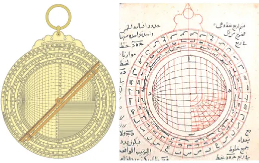
Figures 3a and 3b. The front side of the universal astrolabe. In this drawing, the latitude
circles of the Tropics of Cancer and Capricorn are drawn with dotted lines.34
Because circles are preserved in the stereometric projection theory, the circles above and below the equatorial circle are known as the declination and right ascension angle circles for the equatorial coordinate system and the circles located above and below the ecliptic are known as the latitude and longitude circles for the ecliptic coordinate system. The axis passing through the center of the plate is called
34 The front face drawing in Figure 3b has been prepared based on the instrument located in the Mathematical Tools Collection of the National Library of France (registered as “3a” in the registration number CPL, Reg B 1607; cote Ge A 408. The tool was purchased by the German traveler Ernst Gustav Schultz (1811-1851) in Istanbul, changed hands several times, and finally became the property of the National Library of France. The tool, which was not seen in the National Library of France between 1890 and 1920 was found in the Cattaoui Pacha Collection in Cairo and offered for sale in Sotheby in 1959 when it was owned by R. Weinsteg. It was brought back to the National Library of France through Parisian antique dealer Nicolas Landau (1887-1970). See Anthony Turner, Silke Ackermann and Taha Yasin Arslan, Mathematical Instruments in the Collections of the Bibliothèque Nationale de France, (Paris: BNF Editions, 2018), 37.
the meridian (noon circle). The front surface of the universal astrolabe shown in
Figure 3 is generally obtained when the declination and right ascension angle of the
equatorial coordinate system and the latitude and longitude circles of the ecliptic coordinate system are drawn 5° apart; each dial is graded between 0° and 90° to the edge of the plate and rotated 90° to the position projected around the center of the plate.
In this case, longitude degrees between 5°-(1)80° are recorded using abjad numerals in 5° intervals from top to bottom and degrees between (1)85°- (3)60° are recorded from bottom to top on the vertical axis representing the equator. Due to the limited space, only two digits from these values are written.
The intersecting diameter forms the projection of the ecliptic; when the sun passes through the equinoxes in the center of the plate, the circles contact the periphery. The sun moves along the ecliptic throughout the year. On the ecliptic axis, the Zodiac signs are written from top to bottom (Cancer-Sagittarius) and from bottom to top (Capricorn-Gemini) starting from the point ε ≅ 23,5° which is the inscribed angle. Between two Zodiacs whose signs are 30° apart, the Sun’s longitude (λ) is written from top to bottom (30°-180°) and from bottom to top (210°-360°). The ecliptic axis is also delineated in 1°, 5°, and 30° demarcations as short, medium, and long values. The plate is divided into 5° segments, with the upper and lower points of the arc’s height on the circumference being around 0° and the poles being at 90°; also, 1° segment marks are added to the inner edge of each 5° segment.
Drawing the Front Surface of the Universal Astrolabe
Although the plate of the astrolabe looks complicated at first glance, its drawing is not hard. In order to easily read the location of a point on the plate, the diameter should be chosen as large as possible for the plate. The most advanced instruments that have survived have a diameter of 38 cm. When constructing a universal astrolabe, the following processes are generally applied in order. First, the outer circle and the circumference indicator are drawn in such a way that enough space will be left inside for the drawings. The first four quadrants that follow are divided counterclockwise between 0° and 90° so that 1° marks are represented with short lines and the 5° marks are represented with longer lines, 10° marks also have separate representations.
The equatorial and meridian planes are drawn as two diameters perpendicular to each other. As we can see in Figure 4 with respect to the right ascension, if D is the distance to the plate center of each point that the stereometric trace is projected on the plate, R is the large circle radius, and α is the center angle of the trace point, the relationship D = R is provided in accordance with the right triangle AOE.35
Figure 4: Drawing the latitude (declination or height) arcs.
The latitude arcs are usually drawn on the plate from 5° to 85° at 5° intervals. In accordance with Figure 5, having c = central distance of the latitude circles, r = radius, R = plate radius, and β = latitude in degrees enables the relationships c = R/ (sin β) and r = R/ (tan β). 36
35 Here, the relationships of the plate perimeter angle of ∠(AEO) = α/2, the plate central angle of ∠(A′OC) = α, AO = D, and A′O = EO = R are valid.
36 It should be noted that while deriving these expressions, angles are preserved in the stereometric projection and latitude circles should be perpendicular to the largest longitude circle. Accordingly, the distances of the latitude circles to the center of the plate O are calculated as c = HO and their radius is
Figure 5. Relationship of latitude arcs and the radii.
The results of c/R = 1/(sin β) and r/R =1/(tan β) for the latitude circles are calculated with β = 5° intervals and for the tropic with 23,5° degrees and then listed in Table 1.
β°
c/R = 1/(sin β) r/R =1/(tan β) 0°
∞ ∞ 5°
11.4737 11.4301 10°
5.7588 5.6713 15°
3.8637 3.7321 20°
2.9238 2.7475 23°
30’ 2.5078 2.2998 25°
2.3662 2.1445 30°
2 1.7321 35°
1.7434 1.4281 40°
1.5557 1.1918 45°
1.4142 1 50°
1.3054 0.8391055
°
1.2208 0.70021 60°
1.1547 0.57735 65°
1.1034 0.46631 70°
1.0642 0.36397 75°
1.0353 0.26795 80°
1.0154 0.1763 85°
1.00382 0.0875 90°
1 0Table 1. Values for Latitude Circles at 5° intervals of ß.
Drawing the Longitude (Polar arcs)
As shown in Figure 6, the longitude lines (i.e., pole arcs) are presented with a circle of radius r on the central tropic line x distance from the center of the plate where λ is the central angle and R the plate radius.37
x = R.(tan λ/2) , r = R./ (sin λ)
Figure 6
37 As x = BC, R = DC, and the circumference angle ∠(CDB) = λ / 2 in Figure 5, the relation x = R. (tan λ / 2) from ⊿DCB in the moderation plane is valid. Also, as ¯BC is mutual and DC = KC = R, ⊿KCB in the equatorial plane is equal to ⊿DCB in the median plane. Accordingly, ∠(DBC) = ∠(KBC) = [90°- (λ/ 2)]. Also, as the pole projection ¯KB must have the relation KF = FB = r, ∆KBF is isosceles. As the sum of the angles in a triangle must be 180°, the relation leads to ∠(KFB) = λ, accordingly proving the validity of the relationship r = R/( sin λ) in ⊿KFC.
If the central angle λ of the celestial arcs is calculated at 5° intervals, the calculations for length x / R and radius r / R ratios are given in Table 2:
λ° x/R = (tan λ/2) r/R =1/(sin λ) 5° 0.0437 11.4737 10° 0.0875 5.7588 15° 0.1317 3.8637 20° 0.1763 2.9238 25° 0.2217 2.3662 30° 0.2679 2 35° 0.3153 1.7434 40° 0.3640 1.5557 45° 0.4142 1.4142 50° 0.4663 1.3054 55° 0.5206 1.2208 60° 0.5773 1.1547 65° 0.6371 1.1034 70° 0.7002 1.0642 75° 0.7673 1.0353 80° 0.8391 1.0154 85° 0.9163 1.0038 90° 1 1
Table 2. Length and radius ratios for 5° Intervals of Central Arc Angle λ
The Locations of the Stars
Finally, what remains left is placing the fixed stars on the front face of the universal astrolabe. The names, brightness, and positions of the fixed stars whose locations are marked in astrolabes in Islamic civilization are given in Table 3, which has been created using the star information engraved on the tool in Figure 3a. On the front face of the tool in Figure 3a, the star names are embroidered on the surface with Arabic lettering and a marking that expresses the star brightness. The brightness displayed next to the star name uses a large sign for brighter stars and a small
sign for less bright stars. The star coordinate information in the table was created by measurements made from the star markings on the tool. It does not give the current coordinates of the stars but does give the coordinate information of the stars for the time the instrument was made. Also, the names modern astronomy uses for the constellations and stars have been added to the table.
From the south pole to the equator
No
Name used in
astronomy Common Usage In Arabic
Arabic
Spelling Brightness Declination
Arc Angle 1 α Centaurus Centaurus Rijl
al-Qantūrus سروطنقلا لجر ʘ − 58° 327°
2 α Eta Carinae Canopus Suhayl لیهس ʘ − 52° 90°
3 π Vela
(Constellation)
-Mujdhāf
al-Safīna هنیفسلا فاذجم ʘ − 51° 64°
4 α Vela - Munīr
al-Safīna
رینم
هنیفسلا ʘ − 44.5° 64°
5 δ Eridanus - Ākhir al- Nahr رهنلارخا ʘ − 43.5° 39°
6 λ or υ Scorpius λ:Salva
υ:Lesath Al-Sawla هلوسلا ʘ − 41° 300.05°
7 α Piscis
Austrinus Fomalhaut Famm al-Ḥūt توحلا مف ʘ − 36° 334°
8 ζ Sagittarus Ascella IbṬ al-Rāmī یمارلا طبا ʘ − 30.05° 270.2°
9 α Scorpius Antares Qalb al-‘Aqrab برقعلا بلق ʘ − 24° 235.35°
10 ι Cetus Deneb Kaitos Shemali
Dhanab
al-QayṬūs سوطیقلا بنذ ʘ − 22.05 0.05°
11 ζ Cetus Baten Kaitos Matāyin al-
QayṬūs سوطیقلا نیاتم ʘ − 15° 17.5°
12 α Canis Major Sirius Al-‘Abûr روبعلا ʘ − 15° 93.04°
13 β Orion Rigel Rijl al-Jawzā’ ءازوجلا لجر ʘ − 10° 112°
14 α Virgo Spica Al-A‘zal لزعلاا ʘ − 7.4° 190.83°
From the north pole to the equator
1 γ Ursa Minor Pherkad Al-Farqad دقرفلا ʘ 77° 225°
2 α Ursa Minor Polaris Ẓahr al-Dubb رهظ
بدلا ʘ 66° 151°
3 β Cassiopeia Caph Al-Khaḍīb بیضخلا ʘ 54.05° 189°
4 η Ursa Major Alkaid Al-Qāi’d دئاقلا ʘ 53° 194°
5 α Auriga Capella Al-‘Ayyūq قویَّعلا ʘ 44° 115°
6 α Cygnus Deneb Al-Radif فدرلا ʘ 42.6° 303.6°
7 β Perseus Algol Ra’s al-Ghūl لوغلا سار ʘ 38.4° 35°
9 α Gemini Castor Ra’s al-Tuwām ماوتلا سار ʘ 34.05° 101° 10 α Corona
Borealis Alphekka
Munīr
al-Fakka هکفلا رینم ʘ 30° 225°
11 α Pegasus Andromeda Surrat al-Faras سرفلا ةرس ʘ 25° 351°
12 α Sagittarius Arcturus Al-RāmiḤ حمارلا ʘ 24° 336°
13 β Leo Denebola Al-Sarqa هقرسلا ʘ 19° 166°
14 α Leo Regulus Qalb al-Asad دسلاا بلق ʘ 15.7° 141.40°
15 α Taurus Aldeberan Al-Dabarān ناربدلا ʘ 14.7° 58.06°
16 α Aquila Altair Al-Ṭāʾir رئاطلا ʘ 5.9° 286.67°
17 α or β Canis Minor
α: Procyon
β: Gomeisa Al-Ghamyus سیمغلا ʘ 7° 104°
18 α Orion Betelgeuse Mankab
al-Jawzā’ ءازوجلا بکنم ʘ 5° 120°
Table 3. List of the Fixed Stars
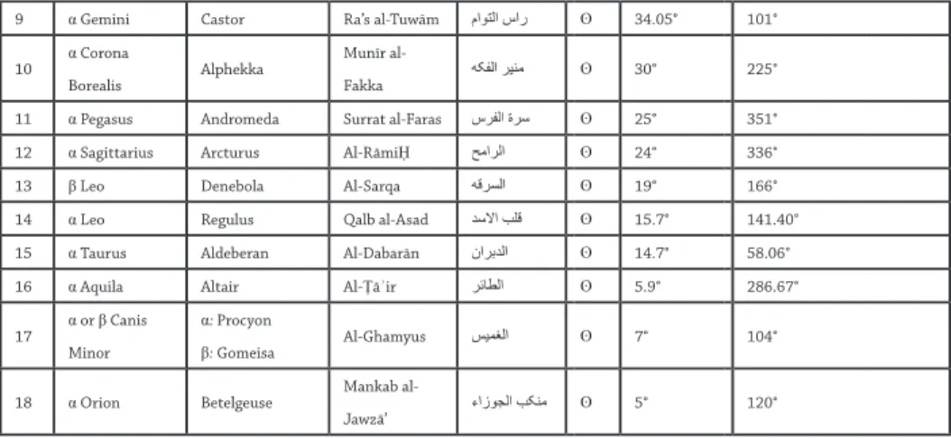
Back Surface
Altitude Scale (also known as shadow square). The altitude scale, or shadow
(bell) square, is arranged as an ABC right triangle using the relation h =tanˉ¹ (p/12) in accordance with Figure 7, which claims AC = p, BC = 12 digits. The plate generally includes the following values:
Figure 7 p 1 2 3 4 5 6 7 8 9 10 p/12 1/12 1/6 1/4 1/3 5/12 1/2 7/12 2/3 3/4 5/6 h [°] 4.764° 9.462° 14.036° 18.435° 22.62° 26.57° 30.26° 33.69° 36.87° 39.81° p 11 12 14 16 18 20 22 24 27 30 p/12 11/12 1 7/6 4/3 1 1/2 5/3 11/6 2 27/12 2 1/2
h [°] 42.51° 45° 49.4° 53.13° 56.3° 59.04° 61.39° 63.44° 66.04° 68.2° p 33 36 39 43 48 60 p/12 11/4 3 13/4 43/12 4 5 h [°] 70.02° 71.57° 72.9° 74.41° 75.96° 78.69°
Table 4. Shadow Squares
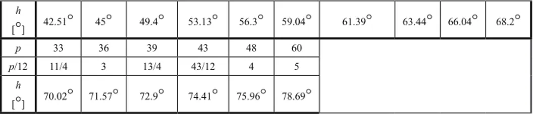
Celestial Circles
According to Figure 8, if the radius of the central circle is R = AB, the radius of the celestial circles are r = AD and the distance from point E to the center of point B where these circles intersect the BD axis can be written as R²+(r-x)²=r² as a result the relationship in ⊿ABD..
Figure 8.
The radii of the celestial circles are obtained from the expression r = (x² + R²) / 2x. Additionally, if k = (0,1,2,…,12) and R = 60 where x = k (R / 12) = k (60/12) = 5k, then the radii of the desired circles can be written as (r / R) = (k2 + 144) / 24k. Table 4 shows the calculations for circles of k = (0,1,2,…,12) with length x, ratio r / R, and diameter d = 2r.
k x r/R d =2r 0 0 ∞ ∞ 1 5 6.042 725 2 10 3.083 370 3 15 2.125 255 4 20 1.667 200 5 25 1.408 169 6 30 1.250 150 7 35 1.149 137.86 8 40 1.083 130 9 45 1.042 125 10 50 1.017 122 11 55 1.004 120.45 12 60 1 120
Table 5. Calculations for Circles with Length x, Ratio , & Diameter
Month names. While Marrākushī gives the relationship between the horoscope
degrees and the Gregorian calendar in the universal astrolabe, the month names in the Coptic language are usually given.
English Coptic Writing
March Barmahāt تاهمرب April Barmūda هدومرب May Bishnas سنشب June Ba’ūna هنوؤب July Ibīb بیبا August Masrā ىرسم September Tūt توت October Bāba هباب November Hatūr روته December Kahwāk/Kihāk كاوهك January Ṭūbā ىبوط February Imshīr ریشما
Figures 9a and 9b. Backside drawings on the universal astrolabe.38
Trigonometric calculations used by Zarqālī in the projection drawing provide sufficient information for its usage, but it does not provide information about which formulas it is calculated with.39
IV. Five-Part Translation Commentary to the Projection of the
Zarqāliyya and Shakkāziyya Plates
Part 1. Issues needed to be known in order to draw a plate. The first of these points is the center, which determines the projection surface and is one of the two poles of the circle passing through the four poles. If the center that determines the plate surface is selected as specified, the measuring surface of this plate consists of surfaces parallel to the circle that passes through the four poles. As a result, the four-pole circle is projected onto a parallel plane as a full circle in such a way that its center becomes the plane’s center.40 The center of this circle is the projection
38 Just like the front side, the tool in Figure 3a is used in drawing the backside. 39 King, In Synchrony with the Heavens, 130.
40 In other words, all surfaces parallel to the large circle passing through the four poles consist of similar surfaces relative to the projection center. Four of the projection poles are located on the disk circle, the other two are on the equatorial circle. The center of the plate is where the orthogonal axes intersect, connecting the north and south poles of the celestial sphere, the Summer and Winter solstices and the
center. The equator (ruling circle) and each of the zodiac belts form a straight line passing through the center of the plate.
As for the circles passing through the two poles of the meridian circle and the others; these have different sizes and are all circles that intersect with the meridian circle’s poles. The center for all is located on the equator line, which determines the middle of the day (meridian/noon). All the circles parallel to the meridian line are not parallel with each other. Their centers are located on the surface of the circle line passing through the poles that determine the meridian. As for the circles passing through the two poles of the zodiac belt, the circle passing through the plate surface forms a line. The other circles are not equal to one another. All of these intersect at both poles of the zodiac belt. The centers for all of these are located on the straight line that comprises the drawing of the zodiac belt. As for the circles parallel to the zodiacal belt, they form non-parallel circles, all of which are located on the straight line that passes through the two poles and the surface designation point of the central zodiac belt.
Part 2. Constructing the Zarqāliyya plate and drawing the front face. As for the construction of the zarqāliyya plate, a fully circular, very thick, and thus inflexible plate is received. The two faces of this plate should be parallel and completely flat and smooth. It has a spline for the hanger around the plate just as in the astrolabe. When the plate is suspended by its strap, a plumb hanging from the center of the hanger nail must correspond to the middle of the line passing through the center of the plate. This point is the center, and three concentric circles are drawn on one side of the plate. The circle with the largest diameter is closest to the outer edge of the sheet. Between the middle circle and largest circle, the multiples of 5 must be in an area where it can be written in order using abjad numerals. The distance between the smallest and middle circles should be sufficient for seeing the degree scale. The smallest circle is located opposite the circle passing through the four poles.
Two diameters that intersect at right angles to the center E of the largest circle are drawn. One of these diameters passing through the plane’s center E is the
Spring and Autumn equinox points. The front surface of the Zarqāliyya plate has drawings of the fol-lowing circles: (i) The central large circle that forms the outer perimeter of the tool and passes through the four poles of the equator and ecliptic; (ii) celestial elevation passing through geographic poles and small orbit or Spring angle circles parallel to the equator; (iii) small latitude circles parallel to the large longitudinal and Zodiac that passes through the poles.
straight line also passing through the hanger nail and falling against the projection of the equatorial plane. Here the diameter AB falls against the equatorial circle (or equatorial horizon). The other diameter CD perpendicular to this is the projection of the Earth’s axis passing through the celestial poles and the center E. Both ends
A and B of the equator line determine the two poles of the line CD that determines
the meridian circle. The north (point D) remains to the left of the person looking at the plate surface suspended on its hanger and refers to the north pole of supply. It is clear that these two diameters divide the large, medium and small circles into four equal portions. A quarter of the largest circle is divided into 18 equal parts.41 One end of the ruler is brought to E, the other end is brought to both the beginning and end of each section and then a line is drawn between the large and small circles. A quarter of the smallest circle is also divided into 18 equal portions. Each of these sections is also divided into five equal parts. Thus, every quarter of the smallest circle is divided into 90 equal parts.42 By placing the end of the ruler along the end of each of these sections and point E, a line is now drawn between the small circle and the middle circle. As is customary and seen in the picture, each of these sections is written with degree values that start at the equatorial horizon in each quarter and ends at the poles; each of these degrees is also divided as much as possible into minutes as subunits.
A slope is marked from the top point of the upper quarter of the southern half of the circle passing through the four poles, signified as the largest solar slope (ε = 23.5°), and a diameter of the small circle is drawn across this sign. This diameter refers to the Zodiac. Also another slope is taken as the complement of the highest solar slope in the top quarter in the northern half of the circle passing through the four poles (90° − ε = 66.5°) and marked in the same way. This sign corresponds to the northern pole of the Zodiac. A diameter is drawn on the circle passing through the poles through this sign. The other end of this diameter is located on the lower quadrant of the southern half of the circle passing through the four poles, which corresponds to the south pole of the Zodiac.
The plate is placed on a firm, flat-surfaced piece of wood so that its surface matches the surface of the four-poled circle. Two full straight lines are drawn on
41 Since a quarter circle = 90°, the dial is divided into 5° intervals (90 / 18 = 5).
42 In addition, since each compartment has 5 subunits, each dial (18 × 5°) = 90 individual degree markings and consequently the circle has (90° × 4) = 360 individual degree markings with each sub-division being 1° on the small circle.
the wooden surface in the direction of the equatorial horizon AB and the equinox axis CD. Likewise, lines in the direction of the Zodiac (ε = 23.5°) and the poles of the Zodiac (90° − ε = 66.5°) are drawn.
Drawing the orbit (right ascension) and latitude circles. The orbit (right ascension)
circles are perpendicular to the equatorial circle and the latitude circles are perpendicular to the longitude lines parallel to the Zodiac. The zodiacal line is also a line that falls against a latitude circle in this device. The orbits and the latitude circles are different circles than the equatorial and zodiacal circles. The condition for accurate observation with this tool is to express the orbit and latitude values with digits of equal value. For this reason, the values for right ascension and latitude are taken from the equator using digits with intervals of 5°. If considered necessary, digits’ intervals can be decreased (e.g., 10° intervals) or increased (1° intervals).
Let’s follow the exact same method suggested by the inventor.43 For this, let’s bring one end of the ruler passing through the center projection E to the end of
FE = 85° at the upper south quarter of the circle passing through the four poles.
We know that in this case, the ruler cuts the circle at points L and M (Figure 10). Similarly, if the ruler is brought to the end of the lower southern quarter so that it passes through point E, the ruler intersects the circle at points L” and M”. In this case, if lines LM and L”M” are drawn, line CD bisects them at points N and N” due to symmetry. If both the lines LL” and MM” are added an angle of NLP = E = 5° to final FE = 85°, the ratio of the distances from point P to points E and L are the same ratio of the distances from the point L to points P and N (PE / PL = PL / NP). One end of the caliper is placed at point P and the other at point L. The arc LL’L” is then drawn. This is the sought-after 85° south celestial arc. If these operations at the south pole C are repeated at the north pole D, the 85° north celestial arc MM’M” is similarly obtained because the two arcs are both 85° from the equator circle AB in the southern and northern directions.
The method is carried out in both directions of the equator and every four quarters of the celestial circle at intervals of 5°. When done correctly, the distances from the south and north celestial poles to the equator should remain the same.
43 There are differences, shortcomings and errors among the existing manuscripts on drawing the elevation and the latitude circles. In the comment given here, the method used in the text is simplified and the letters in Figure 10 are used instead of the complex naming in the original text.
The azimuth of the poles to the equator circle is 90°.44 The same method is applied to the zodiac belt and zodiac pole that makes an angle ε of 23.5° with the equator horizon EU and celestial axis CD; latitude circles in both directions of the zodiac belt are at 5° intervals.
Drawing the declination and longitude circles. Regarding the declination and longitude circles, these are understood to be circles perpendicular to the equator and zodiac. The person who designed this tool placed the circles at 5° intervals around the equator with respect to the meridian circle, which is also a declination circle. Longitudinal circles are similarly placed at 5° intervals around the zodiac belt with respect to the zodiac axis. The starting point is point A where the circle passes through the four poles intersecting the equator. If desired, smaller or larger intervals may be selected. Here we will continue to follow the method proposed by the inventor of the instrument.
44 If the angle of elevation or latitude to be drawn is β = 85° and the plate radius is R, the angle ∠AEL = β is taken in the elevation circle (see Figure A1) and the radius L = R is obtained by drawing the radius
EL = R. If tangent LP is drawn at the point L in circle AMDB with center E, then arc LL′L″ with center P
and radius r = LC is opposite the sought projection arc. Clearly in this case r = R / (tan β) and EP = c =
R / (sin β) because ∠AEL = ∠ELN = ∠NLM = β. In the text, the tangent LP is obtained by adding an
angle to ∠ELN = β = 85°, complementing ∠NLP = (90° - β) = 5°. As shown in the figure, PE / PL = PL / PN or PL² = (PE PN) relationships can be derived from the similarity rule for ⊿ELP and ⊿PNL.
The solution proposed by the designer is based on one end of the ruler being placed at point C, which falls against the southern equatorial pole. The other end of the ruler is brought to the end of the lowest quarter of the azimuth circle in the north, which reads FE = 85° (i.e., 90° − λ; see Figure 11).45 In this case, the ruler bisects the equatorial line AB at point F. Point F is connected to the north pole D. The line DF is bisected with the points of the compasses from the point G so that
GD = GF. Then, with the help of a compass, line GP is drawn perpendicular to line DF. If one end of the compass is placed on point P and the other on point F, the
arc DFC can be drawn. Thus, an elevation arc is obtained for the desired λ = 5° and the complementary angle (180° − λ = 175°). Likewise, these circles continue to be drawn until 85° is reached. The circles between 180° > λ > 360° are determined by taking the symmetry of the circles related to the angle values for 0 > λ > 180° with respect to the axis CD.
45 The geometric drawing is given in Figure 11: The declination/longitude angle λ and plate radius R in-tended to be drawn are obtained from the azimuth circle passing through the four poles, ∠HEB = λ and circumference ∠HAB = λ / 2. The length EN = x is taken from EF = EN = x = R (tan λ / 2). The lines FC = FD are drawn, point G occurs at the middle line FD, and the perpendicular line GP is drawn to obtain point P. The arc CFD centered with P determines the longitude radius due to the equality of isosceles triangles PDF and PCF and the right triangle PDE.
The lengths of the declination circles to the summer solstice are written through the top half of the celestial circle in the northern hemisphere. In this case, the numbers start at point A on the equator just below the ring and reach 180° at point B at the bottom. Then, the numbers rise to the equator in the southern hemisphere, reaching 270° at point HX, increasing to 360° at the top of the equator, which is also the beginning. Then, starting from the top half of the celestial circle along the equator line on the plate, the values for the longitudinal circles are written in 5° increments starting from the north pole. The values increase to 180° once it reaches the bottom-most point opposite the top. Then the longitudes after this point at the south pole are numbered from 185° to 360° in 5° intervals going back from the bottom to the top.46 In order to place the complementary angles for obtaining the longitudinal arcs, the DF’C symmetry needs to be taken with respect to the axis CD of the arc and then the axis CD needs to be turned positively around the center E by ε = 23.5°.
Afterward, the two sides of the Zodiac line are divided into zodiac signs with three 10° sections (3x10° = 30° longitudinally) per sign and their names are written on each. These are related to one another and to the longitudinal circles that cross the Zodiac. Capricorn begins at the top of the Zodiac and ends at 30°. Aquarius begins at the end of Capricorn and ends at the 60° longitudinal circle. Pisces begins at the end of Aquarius and ends at the point E. Aries starts at point E and ends at 120°. Taurus starts at the end of Aries and ends at 150°. The Gemini Zodiac begins at the end of Taurus and ends at the bottom of the Zodiac. The Cancer Zodiac begins at the end of Gemini and ends at the sign of Leo. The sign of Cancer and subsequent signs are written in the southern half of the Zodiac. Leo begins at the end of Cancer and its end is at the beginning of Virgo. The starting point of the Virgo is the end of Leo and its end is at point E. Libra’s starting point is point E and ends at Scorpio. The beginning of Scorpio is the end of Libra and its end is the beginning of Sagittarius. The beginning of Sagittarius is the end of the Scorpio and its end is the highest point of the Zodiac.
Determining the positions of the fixed stars. If the longitude, latitude, and
direction of latitude are known for a star desiring to be identified, the longitude in question is determined in the zodiac belt and the latitude that intersects this
46 Due to the shortage of space, only the lowest two digits are written in these abjad numbers. According to this, it is written from top to center [5°-90°], from center to bottom [95- (1) 80], from bottom to center [(1) 85- (2) 70] and from center to top ((2) 75- (3) 60].
longitude is marked, thus determining the latitude passing through the sign. In this way, northern latitudes are combined with northern longitudes and southern longitudes are combined with southern latitudes. For the point found for representing the center of the star, a small circle is drawn around this point and the name of the sign in which the star is located is written. If the star’s angular distance, direction, and time of rising according to the beginning of Capricorn are known according to the meridian line, the location of the star is determined by its time of rising and its direction in the transition interval. The determined trajectory and transition interval meet at this point. This point represents the center of the star. A small circle is drawn here and the name of the star is written. During its rising, for the points whose angle is less than 180°, the name of the star is written below the point, while it is written above the point if they are greater than 180°. If the star’s declination and right ascension are known, its location is certain. Obviously, the position of a star with a declination and right ascension can be determined just using an astrolabe. Let this be known: It is Allah Who leads us to the truth. He is enough for us, what a good foundation He is. And this is the form (Figure 12):
Figures 12a and 12b. Drawing of the front face of the plate zarqāliyya.47
Part 3. The drawings on the backside of the Zarqāliyya plate. The first outer indicator of this face is the angle of declination and has tangent (shadow) values associated with them. For this, three central circles are drawn on the first side of the tool. As customary for the first two quarters under the sling, the angles of declination are written in 5° intervals. The numbers start from the perpendicular diameter through the sling. In the remaining two quarters, the tangent and inverse cotangent values are written with the units of finger width. How these are written is clear as it is known from the rub‘ al-muqanṭarāt. Behind the azimuth and tangent circles are solar calendar circles, which will be explained later.48 As on the other side, the solar calendar circles here are separated into 5 and multiples of 5. The largest of these circles are very close to the smallest of the solar calendar circles. The smallest of these circles is circle ABC with its center at the center of the plate and its diameter passing through the hanger. When hung on the plate hanger, the letter B is located on the left side of the person looking at the plate, the letter C is at the bottom of line AC passing through the hanger, and the letter D is on diameter
CD perpendicular to the diameter AC on the right side of the person looking at
the plate. The multiples of five begin at points D and B in the quarters AD and EU,
47 Marrākushī, Jāmiʿ al-mabādī, Ahmed III, 11a; Marrākushī, Jāmiʿ al-mabādī wa-l-ghāyāt fī ʿilm al-mīqāt,
National Library of France, MS 2508, f. 60a.
ending at 90° (which equals SA) at point A49. Similarly, it starts at points B and D in the quarters DC and BC and ends at 90° (SA) at point C.
The diameter AC is then divided into 120 equal segments.50 If a deficiency remains when done as specified, additional or less segments are made. Each section is sub-divided into 120 equal parts. The plate diameter AC is usually divided into 24 equal segments first. In this example, we have also divided it into 24 equal segments. Each of these sections contains 120 segments, 24 when divided by 5 (). Then the intermediate lines are drawn. Each of these passes through two points on both sides of the diameter AC equidistant from the center. The largest diameter is the line BD. The shortest radius is one of the two ends of diameter AC and the plate center. This issue has already been dealt with in the eighth part of the previous section.
How to draw the cross lines of a plate whose shortest and longest radii are
49 The partitioning of this indicator is different in various manuscripts. In the narrative here, the drawing was adhered to.
50 It consists of the sum of the radius of the diameter AC (AE + EC). Since each radius is divided into 60 parts, the diameter AC is divided into 120 parts. This and the subsequent explanation are in accordance with the drawing in Figures 13a and 13b, which are partially available in the text:
Figure 13a: Back side of a zarqāliyya plate / Figure 13b: Marrākushī, Jāmiʿ al-mabādī , Oxford
known? According to the statement of the inventor of this instrument, intermediate lines are drawn as follows: if the largest diameter is the circle diameter and the circle also has a beam parallel to the shortest diameter, the ratio of a circle radius to the shortest radius is the ratio of the half beam to the intermediate line. (The ratio of a circle radius to the shortest radius is the ratio of the beam to the semi-beam). The proof for this is that when the lines parallel to diameter AC in the conics are divided by the number AC and then the lines after diameter BD are combined, they form the approximate circumference of the circle in which the intermediate lines are drawn. The perimeters of the other points are combined in the same way. If each line parallel to diameter AC is divided by the number of segments AC has and then combined with the points from diameter BD, it will have approximately the circumference of the intermediate lines. This process continues until the end. The process is really beautiful.51
The left half of circle ABC has lines parallel to the diameter AC as shown above. These lines are not found in quarter CD beyond point E. These are the beams coming out of the end of the 5-degree scale in the quarter EU and are parallel to diameter AC. In contrast, the sines parallel to diameter AC exit from the end of quarter AD. These sines end at line ED and do not extend beyond it. Each of these lines resembles AE. When one reaches the quarter, the CD passing through point
E is drawn. Because the upper half is not needed, row lines are not found. Lines
parallel to line ED are drawn from each point in the segments of EC. These lines extend to arc CD and do not extend past it. Each segment of line EC is then divided into five equal parts. Four points are placed in each section, which constitutes the boundaries of the 5 sections. Each of these draws a line parallel to line DE from the quarter CED. These also extend only as far as arc DC . The number of rows in the quarter CED is about 60. The segments for EC are also as many as 60. These are also called the sequential segments of the lines. Six 5°-segments are taken from the lines in sequence with the compass. When the compass remains at the same angle, its points falls against 3 of the parts (2.5°) on line EC with respect to the center of this plate. By centering this we draw a circle with the other end, then we draw a slightly smaller circle to the center of it. We divide the circumference of the largest into 24 equal portions. This starts from line EC. One end of the ruler is placed at the center of this circle and the other end on each part around it, and
51 Let’s assume that radius AE = R is divided by k. Accordingly, the smallest radius will be r = R / k. So (large circle circumference) / (smallest circle circumference) = 2πR/2πr = R/r = k is valid.
a line connecting the two circles is drawn but does not extend past them. Then, as before, we write each of these curved lines from point E to the hanger and proceed 5 times the distance from the center to the bottom. Success is from Allah.
Figures 14a and 14b: Backside drawing of the plate Zarqāliyya.52
Part 4. Constructing the instrument rulers. Two rulers (alidades) are needed on the surface of the plate where the declination measurement and sun-setting will be made. One of these is the ascension ruler, the function of which has also been made clear as mentioned earlier. This ruler must pass through the center of the board to line up with diameters AC and DB. The other one which is the sunset ruler, is an exclusive ruler and serves a special purpose. Its length is the same as diameter AC. As long as the declination ruler is properly attached to the plate, this ruler must also be attached to it. Both long sides of this scale parallel to each other should be at right angles to the declination ruler passing through the center. When one end of the declination ruler is brought to any point on diameter AC, the tip of the small ruler should be at right angles to any of the regulation lines. This process should be done comfortably so that the arm that cuts the end of the right angle elevation ruler during the adjustment does not move. The two ends of the ruler between the abjad circle and the center are segmented as in radius EC. 53 Writing the distances from the center of these sections is not a problem.
52 Marrākushī, Jāmiʿ al-mabādī, Ahmed III, f. 14a; Marrākushī, Jāmiʿ al-mabādī, National Library of
France, f. 61.
53 Because 180° = (2 × 90°) = 2 × (18 × 5°), as seen in Figure 3a each arm of the ruler has 18 items of 5° parts.