IJISAE, 2016, 4(2), 29-32 | 29
GA Based Selective Harmonic Elimination for Five-Level Inverter Using
Cascaded H-bridge Modules
Enes Bektas
1, Hulusi Karaca
*2Accepted 30th May 2016 DOI: 10.18201/ijisae.97681
DOI: 10.1039/b000000x
Abstract: Multilevel inverters (MLI) have been commonly used in industry especially to get quality output voltage in terms of total harmonic distortion (THD). In addition, development in semiconductor technology and advanced modulation techniques make MLI implementation more attractive. Selective Harmonic Elimination (SHE) that can be applied MLI at desired switching frequency offers elimination of harmonics in the output voltage. Also, by using SHE technique with cascaded H-bridge multilevel inverters, the necessity of using filter in the output can be minimized. In this paper, SHE equations have been solved by using of Genetic Algorithm (GA) Toobox&Matlab and it has been aimed to eliminate desired harmonic orders at fundamental output voltage. Simulation results have clearly demonstrated that GA based SHE techniques can eliminate the demanded harmonic orders.
Keywords: Cascaded multilevel inverter, Genetic algorithm, H-bridge modules, Matlab&Optimization Tooolbox, Selective harmonic
elimination.
1. Introduction
In recent years, power electronic devices have been widely used in many applications. Multilevel inverter (MLI) is a power conversion device having stepped output voltage. Especially together with increasing of demanded power in industry, MLI topology has been used an alternative to traditional two level inverter [1].
Multilevel inverters have outstanding productivity such as low total harmonic distortion (THD) on output voltage, working with desired switching frequency, producing high power ratings and using with renewable energy sources [2,3]. In addition, some low order harmonics can be eliminated by applying Selective Harmonic Elimination (SHE) to MLI topology. SHE technique uses Fourier Series in order to get harmonic equations and needs some methods to solve nonlinear harmonic equations. Analytical methods can be adapted to SHE equations and switching angles can be calculated. But divergence problem may occur with the methods solving the equations analytically. In addition, the solution get by analytical methods needs extra initial value and look up tables for each modulation index [1,4]. Another way to get switching angles is using of soft computing method such as Genetic Algorithm (GA). GA can be used with Optimization Toolbox&Matlab easily.
This paper presents elimination of third harmonic with 0.7 and 1.1 modulation indexes. Nonlinear SHE equations eliminating third harmonic and configuring each modulation index have been solved by using GA Optimization Toolbox&Matlab. Simulation results have been given to demonstrate that GA based SHE technique can be applied to MLI with cascaded H-bridge modules easily by adjusting desired modulation index.
2. Multilevel Inverter using H-bridge Modules
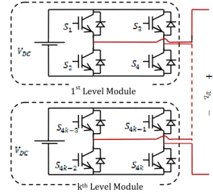
The proposed cascaded multilevel inverter consists of level module units given in (Figure.1). Each level module unit has same H- bridge structure having four power switches. Especially in high voltage levels, hardware of inverter can be formed easily by connecting level numbers in series [5].
Figure 1. Multilevel inverter using H-bridge modules
In (Figure.1), it is clearly shown that each level module has isolated DC sources. In addition, MLI’s maximum rate of stepped output voltage changes according to DC sources value. Symmetric MLI has equal DC sources however asymmetric MLI’s DC sources are not equal to each other.
The level number of cascaded symmetric MLI can be calculated by (Equation.1) and number of switching angles is obtained by (Equation.2) [6].
kth Level Module 1st Level Module
_______________________________________________________________________________________________________________________________________________________________
1 Engineering Faculty, Cankiri Karatekin University – Cankiri, Turkey 2 Technology Faculty, Selcuk University – Konya, Turkey
* Corresponding Author: Email: [email protected]
International Journal of
Intelligent Systems and Applications in Engineering
ISSN:2147-67992147-6799 www.ijisae.org Original Research Paper
IJISAE, 2016, 4(2), 29-32 2 1 level N k (1) 1 2 level N N k (2)
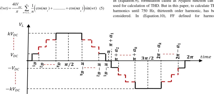
In (Figure.2), the output voltage having stepping waveform is given. Considering that k is the number of level modules, minimum and maximum rates of output voltage are given as:
min DC V kV L_ (3) L_max DC V kV (4)
where, is the value of equal DC sources.
In order to obtain stepped output voltage waveform, represents first level module, defines for second level module and so on. For example, in positive section of three-level output voltage, and are on conducting simultaneously between and . As for in negative section, and are on conducting simultaneously between and . In zero voltage section, and are on conducting because of positive charge current on the inductance. In order to make negative charge current flown on the load, and must be switched simultaneously. Thus, positive, zero and negative DC voltage level can be obtained.
3. Selective Harmonic Elimination Method with
Genetic Algorithm
Selective Harmonic Elimination (SHE) technique enables to eliminate desired any order harmonic in the output. So as to eliminate harmonics with SHE technique, output voltage’s equations have been formulated. So as to get harmonic equations, Fourier expansion of output voltage must be obtained by (Equation.5).
1
1,3,...
1
cos( ) ... cos( ) sin( ) DC k n 4kV V(wt) n n wt n
(5)where, n is the order of harmonics [7]. When (Equation.5) is edited for five-level output voltage, (Equation.6) is obtained and given as:
cos( 1) cos( 2)
DC n 4kV V n n n (6)where, is the n order harmonic content of output voltage. In addition, is the desired fundamental output voltage maximum rate and also is the first order harmonic. To obtain desired amplitude of output voltage, modulation index is defined as:
1 DC V M kV (7)
By using (Equation.6) and (Equation.7) nonlinear SHE equations adjusting modulation index and eliminating third order harmonic can be obtained and given with (Equation.8).
1 2 1 2 cos( ) cos( ) M 2 cos(3 ) cos(3 ) 0 (8)
As mentioned in Section.2, five-level inverter has two switching angles. By using these angles, two harmonics can be controlled. However first of controlled harmonics must be defined for modulation index. In that, with two switching angles, it is possible to eliminate one harmonic component and possible to control desired output voltage [8].
3.1. Genetic Algorithm Toolbox&Matlab
In (Equation.8), nonlinear equations needed for elimination of harmonics have been given. Also, (Equation.8) is a optimization problem having constraints and fitness function. To solve nonlinear equations given in (Equation.8), function of Total Harmonic Distortion (THD) can be defined as in (Equation.9) and fitness function (FF) must be derived from THD equation.
1 2 2 3 .... V V THD V (9)
In (Equation.9), formulation called as Nyquist function can be used for calculation of THD. But in this paper, to calculate THD harmonics until 750 Hz, thirteenth order harmonic, has been considered. In (Equation.10), FF defined for harmonic
elimination is given. As shown in (Equation.10), FF is calculated until 150 Hz, because of only third order harmonic is eliminated. Figure 2. The output waveform of symmetric MLI
𝟑𝝅/𝟐
𝟐𝝅
𝝅/𝟐
𝝅
𝑘𝑉
𝐷𝐶𝑉
𝐷𝐶−𝑉
𝐷𝐶−𝑘𝑉
𝐷𝐶𝑉
𝐿𝜶
𝟏 𝟐𝜶
𝒌𝜶
𝝅
−
𝜶
𝒌𝑡𝑖𝑚𝑒
𝝅
+
𝜶
𝟏𝝅
−
𝜶
𝟏𝝅
−
𝜶
𝟐𝝅
+
𝜶
𝟐𝝅
+
𝜶
𝒌2𝝅
−
𝜶
𝒌2𝝅
−
𝜶
𝟏For example, elimination of third and fifth order harmonics with seven-level inverter FF must be calculated until 250 Hz. Because fifth order harmonic occurred at 250 Hz.
2 3 1 V FF V (10)
Figure 3. Optimization Toolbox&GA interface
To solve nonlinear equations, GA Toolbox needs to the number of variables, fitness function, nonlinear constraint function and switching angle’s bounds. Also, GA Toolbox enables to change mutation type, population type, selection type etc [9].
In (Figure.3), Optimization Toolbox&GA interface is given. A function named as @my_Objective including fitness function
have been created for 0.7 and 1.1 modulation indexes separately by considering (Equation.10). In addition @my_Constraints must be crated. In this function, (Equation.8) must be included and (Equation.11) must be adapted in @my_Constraints [10].
1 2
0 (11)
In Optimization Toolbox, other options needed for elimination of third harmonic are given as:
Population Type: Double vector Population Size: 50
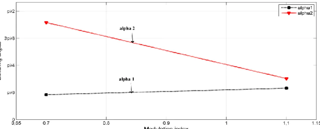
Creation Function, Crossover Function: Constraint Dependent By applying @my_Objective and @my_Constraints crated for elimination of third order harmonic with GA Toolbox, different solution have been obtained for 0.7 and 1.1 modulation indexes. In (Figure.4), solution including switching angles for 0.7 and 1.1 modulation indexes have been given.
4. Simulation Results
In this study, SHE technique has been applied to five-level inverter. Third order harmonic content of output voltage has been eliminated by getting 0.7 and 1.1 modulation indexes. The fundamental frequency is 50 Hz and switching frequency of all power switches is 100 Hz. Simulations have been realized by using Matlab&Simulink. In (Figure.5), five-level output voltage eliminating third harmonic is given for 0.7 and 1.1 modulation index. As stated in before, five-level output voltage has two steps because of (Equation.1). It can be deduced from (Figure.5) that DC sources are 100 V and increasing of modulation index make the switching angles closer to each other.
Figure 4. The calculated switching angles by Optimization Toolbox&GA for 0.7 and 1.1 modulation indexes
Figure 5. 5-level inverter output voltage with SHE eliminating 3rd order harmonic for 0.7 and 1.1 modulation index
IJISAE, 2016, 4(2), 29-32
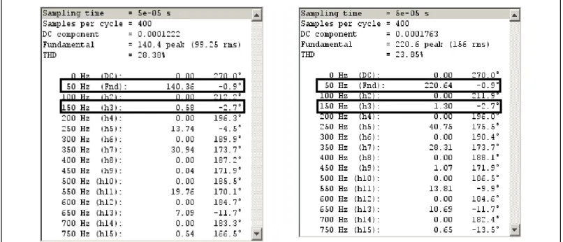
In (Figure.6), harmonic components of output voltage have been given for two modulation indexes by using Powergui&FFT Toolbox. It has been aimed at getting 140 V and 220 V output voltages for 0.7 and 1.1 modulation indexes respectively. As shown in the (Figure.6), first order harmonic that occurs at 50 Hz is the fundamental output voltage. Considering that desired fundamental voltages are 140 V and 220 V for 0.7 and 1.1 modulation indexes respectively, the fundamental output voltage’s maximum rates are 140.36 V and 220.64 V. Thus, fundamental output voltages of 0.7 and 1.1 modulation indexes have been obtained with too little deviation. In addition, third order harmonic component is approached to zero. For 1.1 modulation index, third order harmonic is 1.3 V and it is too little when compared other harmonics such as fifth and seventh. In addition third order harmonic in 0.7 modulation index is quite small and almost equal to zero. As stated in Section.3.1, total harmonic distortion have been calculated until 750 Hz. Total harmonic value of output voltage can be decreased with elimination of more harmonics with higher number of level.
5. Conclusion
In this paper, Selective Harmonic Elimination (SHE) technique with cascaded multilevel inverter using H-bridge level modules has been presented. The advantage of present multilevel inverter is having same H-bridge modules. Therefore the hardware of presented multilevel inverter can be easily formed by connecting H-bridge modules in series. In addition, it has been aimed at elimination of third harmonic in the output by getting 0.7 and 1.1 desired modulation indexes. SHE equations of five-level inverter have been solved by using GA Toolbox&Matlab. The results obtained from simulations have apparently proved that GA based SHE technique can be applied to presented multilevel inverter with desired modulation index.
References
[1] H. Karaca and E. Bektas,“GA based selective harmonic eliminaton for multilevel inverter with reduced number of power switches,” in Proc. of the World Congress on Engineering and Computer Science (WCECS), 2015, vol. 1, pp.204-209.
[2] H. Karaca,“A novel topology for multilevel inverter with
reduced number of switches,” in Proc. of the World Congress on Engineering and Computer Science (WCECS), 2013, vol. 1.
[3] R. Selvamuthukumaran, A.Garg and R. Gupta, “Hybrid multicarrier modulation to reduce leakage current in transformerless cascaded multilevel inverter for photovoltaic systems,” IEEE Trans. Pow. Elec., vol. 30, no.4, pp. 1779-1783, Apr. 2015.
[4] M. H. Etesami, N.Farokhnia and S. H. Fathi, “Colonial competitive algorithm development toward harmonic minimiation in multilevel inverters,” IEEE Trans. Ind. Inf., vol. 11, no. 1, pp. 459-466, Apr. 2010.
[5] J. Rodrígues, J. S. Lai and F. Z. Peng, “Multilevel inverters: a survey of topologies, controls and applications,” IEEE Trans. Ind. Electronics, vol. 49, no. 4, pp. 724-738, Aug. 2002.
[6] E. Bektas and H. Karaca, “Harmonic minimization technique for multilevel inverter using cascaded h-bridge modules,” in Proc. of the International Scientific Conference (UNITECH), 2015, vol. 1, pp.139-143. [7] J. N. Chiasson, L. M.Tolbert, K. M. Kenziei and Z. Du,
“Elimination of harmonics in a multilevel converter using the theory of symmetric polynominals and results,” IEEE Trans. Cont. Sys. Tech., vol. 13, no. 2, pp. 216-223, Mar. 2005.
[8] K. El-Naggar and T. H. Abdelhamid, “Selective harmonic elimination of new family of multilevel inverters using genetic algorithms,” Energy Conversion and Management, vol. 49, pp. 89-95, July. 2007.
[9] J. Baskaran, S. Thamizharasan and R. Rajtilak, “GA based optimization and critical evaluation SHE methods for three-level inverter,” Int. Journal of Soft Computing and Engineering (IJSCE)., vol. 2, iss. 3, pp. 321-326, July. 2012.
[10] S. Debnanth and R. N. Ray, “Harmonic minimization technique for multilevel inverter using cascaded h-bridge modules,” in Proc. of the 2012 IEEE Students’s Conference on Electrical, Electronics and Computer Science (SCEECS), 2012, pp.1-5.
Figure 6. Powergui&FFT Toolbox for 3rd order harmonic elimination with 0.7 and 1.1 modulation indexes