INVESTIGATION OF MOLYBDENUM
OXIDE AS A CATALYST FOR
NON-AQUEOUS LITHIUM OXYGEN
BATTERIES
a thesis submitted to
the graduate school of engineering and science
of bilkent university
in partial fulfillment of the requirements for
the degree of
master of science
in
materials science and nanotechnology
By
Kıvan¸c C
¸ oban
January, 2017
INVESTIGATION OF MOLYBDENUM
OXIDE AS A CATALYST FOR
NON-AQUEOUS LITHIUM OXYGEN
BATTERIES
a dissertation submitted to
the graduate school of engineering and science
of bilkent university
in partial fulfillment of the requirements for
the degree of
doctor of philosophy
in
materials science and nanotechnology
By
Kıvan¸c C
¸ oban
January, 2017
INVESTIGATION OF MOLYBDENUM OXIDE AS A CATALYST FOR NON-AQUEOUS LITHIUM OXYGEN BATTERIES
By Kıvan¸c C¸ oban January, 2017
We certify that we have read this thesis and that in our opinion it is fully adequate, in scope and in quality, as a thesis for the degree of Master of Science.
Eda Yılmaz(Advisor)
Damla Ero˘glu Pala
Ferdi Karada¸s
Approved for the Graduate School of Engineering and Science:
Ezhan Kara¸san
ABSTRACT
INVESTIGATION OF MOLYBDENUM OXIDE AS A
CATALYST FOR NON-AQUEOUS LITHIUM OXYGEN
BATTERIES
Kıvan¸c C¸ oban
M.S. in Materials Science and Nanotechnology Advisor: Eda Yılmaz
January, 2017
Today, one of the biggest problem which the world have to get over is the global warming and the main reason of global warming is the greenhause gasses which are released due to usage of fossil fuels in transportation applications. Therefore, alternative energy sources are needed but it is not sufficient itself. Suitable energy storage systems are also necessary and these systems have to provide very high amount of energy density and efficiency in order to replace fossil fuels. In that case batteries are very promising technologies however, there is no manufactured battery type in the market which can provide required high energy and power density, so new and more effective technologies have to be investigated for this purpose.
One of the best candidates of such technologies is the Li-O2 battery which is
based on the Li-O2 electrochemical couple. Li-O2 batteries can achieve
approxi-mately ten times higher energy density than that of current state-of-the-art Li-ion batteries by storing the discharge product Li2O2 which occurs as a result of
re-action between Li anode and active cathode material, O2, on the porous cathode
material. However, there are various challenges to overcome including high OER-ORR overpotentials, parasitic side reactions and poor cyclability in order to built commercial Li-O2 batteries. Especially, unwanted side product formation on the
cathode-electrolyte interface is the major challenge itself because these insula-tor side products accumulate on the cathode surface during cycling and prevent electrical and ionic transportation which cause drastic capacity fading. That is why various catalyst materials have been investigated in order to facilitate the reaction between Li-O2 electrochemical couple.
v
In this study, we investigated molybdenum oxide which is decorated on multi-walled carbon nanotube catalyst support as an efficient electrocatalyst for Li-O2
batteries. Several synthesis methods and parameters have been utilized in or-der to enhance its performance and adapt it for our application. Morphological, structural, chemical and electrochemical characterizations have been carried out by using X-Ray Diffraction, X-Ray Photoelectron Spectroscopy, Scanning Elec-tron Microscopy and Transmission ElecElec-tron Microscopy.
Keywords: Metal Oxide Catalysts, Non-Aqueous Li-O2 Batteries, Electrochemi-cal Energy Storage.
¨
OZET
MOL˙IBDENYUM OKS˙IT˙IN KATAL˙IZ ¨
OR MALZEMES˙I
OLARAK SU ˙IC
¸ ERMEYEN L˙ITYUM OKS˙IJEN
BATARYALARINDA ARAS
¸TIRILMASI
Kıvan¸c C¸ oban
Malzeme Bilimi ve Nanoteknoloji, Y¨uksek Lisans Tez Danı¸smanı: Eda Yılmaz
Ocak, 2017
G¨un¨um¨uzde, d¨unyanın ¨ustesinden gelmesi gereken en b¨uy¨uk problemlerden bir tanesi k¨uresel ısınmadır ve bu problemin ba¸slıca nedeni ula¸sım ara¸clarında kul-lanılan fosil yakıtlar nedeniyle salınan sera gazlarıdır. Bu y¨uzden alternatif en-erji kaynaklarına ihtiya¸c duyulmaktadır ancak bu kaynakların varlı˘gı tek ba¸sına yeterli bir ¸c¨oz¨um sunmaz. Bu enerji kaynaklarından elde edilecek enerjiyi depo-lamak i¸cin uygun enerji depolama sistemlerine de ihtiya¸c vardır ve bu sistem-lerin fosil yakıtların yerini alabilmesi yeterli enerji yo˘gunlu˘gunu ve etkinli˘gini sa˘glayabilmeleriyle m¨umk¨und¨ur. Bu durumda, piller umut vaad eden teknolo-jilerdir ancak hali hazırda ¨uretilmi¸s hi¸c bir pil sistemi gerekli olan y¨uksek enerji ve g¨u¸c yo˘gunlu˘gunu sa˘glamada yeterli de˘gildir. Bu y¨uzden yeni ve daha etkili teknolojilerin ara¸stırılması gerekmektedir.
Bu tarz enerji depolama sistemlerine aday olabilecek en iyi teknolojilerden bir tanesi Li ve O2 elektrokimyasal ¸ciftinin temel alındı˘gı Li-O2 pilleridir.
Li-O2 pilleri, de¸sarj sırasında Li anot ve aktif katot malzemesi olan oksijenin
g¨ozenekli katot malzemesi ¨uzerinde ger¸cekle¸sen tepkimesi sonucu Li2O2
depola-yarak, g¨un¨um¨uzde kullanılan en teknolojik Li-iyon pillerinden yakla¸sık olarak 10 kat daha fazla enerji yo˘gunlu˘guna ula¸sabilirler. Ancak, y¨uksek oksijen indirgenme ve y¨ukseltgenme tepkimesi potensiyalleri, parazitik yan reaksiyonlar ve d¨u¸s¨uk ¸sarj-de¸sarj d¨ong¨uselli˘gi gibi a¸sılması gereken bir ¸cok problem bu pillerin ticari olarak ¨uretilebilir olmasının ¨on¨une ge¸cer. ¨ozellikle elektrolit ve katot aray¨uzeyinde olu¸san istenmeyen yan ¨ur¨unler ba¸slı ba¸sına ¸cok b¨uy¨uk bir problemdir ¸c¨unk¨u bu yalıtkan ¨ur¨unler d¨ong¨u sırasında katot y¨uzeyinde birikerek elektriksel ve iyonik ula¸sımı engelleyerek ¸siddetli bir kapasite azalmasına neden olurlar. Bu y¨uzden, Li ve O2 elektrokimyasal ¸cifti arasındaki tepkimeyi kolayla¸stırması i¸cin bir ¸cok
vii
¸ce¸sitli kataliz¨or malzeme incelenmi¸stir.
Bu ¸calı¸smada, molibdenyum oksit par¸cacıklarla dekore edilmi¸s ¸cok duvarlı kar-bon nanot¨up katot malzemesi Li-O2 piller i¸cin etkili bir elektrokataliz¨or olabilece˘gi
d¨u¸s¨un¨ulerek ara¸stırılmı¸stır. Bu malzemeyi Li-O2 pillerine adapte edebilmek ve
pillerin performansını arttırabilmek i¸cin ¸ce¸sitli sentez y¨ontemleri ve parametreleri uygulanmı¸stır. Morfolojik, yapısal, kimyasal ve elektrokimyasal karakterizasy-onlar X-Ray Kırınımı, X-Ray Fotoelektron Spektroskopisi, Sa¸cılımlı Elektron Mikropkopu, Ge¸cirmeli Elektron Mikroskopu ve Galvanostatik ¸sarj-De¸sarj Testi kullanılarak ger¸cekle¸stirilmi¸stir.
Anahtar s¨ozc¨ukler : Metal Oksit Kataliz¨or, Su ˙I¸cermeyen Li-O2 Pilleri,
Acknowledgement
I only want to thank seperately my academic advisor, Dr. Eda Yilmaz, for her extraordinary tolerance and great guidance throughout my master degree. Also, I would like to acknowledge TUBITAK, for funding, 114M478 and 115M375 numbered projects.
Contents
1 INTRODUCTION 1
1.1 Renewable Energy Technologies . . . 1
1.2 Brief History . . . 2
1.3 Basic Concepts . . . 4
1.4 Working Mechanism of Li-O2 Battery . . . 6
1.5 Critical Challenges . . . 10
1.5.1 Li-O2 Electrochemical Reaction Mechanisms at Air Electrode 10 1.5.2 Chemical and Electrochemical Stability of Battery Compo-nents . . . 11
1.5.3 Design and Construction . . . 14
1.6 Catalyst and Material Selection for Better Cathode . . . 14
1.6.1 Carbon Materials . . . 15
1.6.2 Transition Metal Oxides(TMOs) . . . 16
CONTENTS x
2 EXPERIMENTAL 20
2.1 List of Materials and Chemicals . . . 20
2.2 Experimental Procedures . . . 21
2.2.1 Materials Preparation . . . 21
2.2.2 Cell Assembly . . . 26
2.2.3 Characterization Methods . . . 27
3 Results and Discussion 30
List of Figures
1.1 Comparison between the specific energy density of different battery technologies.[Ref.7] . . . 3 1.2 Schematic of the four different architectures of Liair battery. [Ref.11] 7 1.3 Working principle of a rechargeable Li-O2 battery.[Ref.16] . . . . 8
2.1 The hydrothermal autoclaves used in this master thesis work. . . 23 2.2 Monowave300 microwave system used in this study. . . 25 2.3 Schematic Shown of Non-Aqueous Li-O2 Battery Preparation . . 27
3.1 a,b) TEM images and c,d) galvanostatic discharge-charge results of pristine CNT and CNT@MoOx samples, respectively. . . 31 3.2 Comparison XPS of a) C 1s and b) O 1s signals from functionalized
nanotubes by three different treatment. . . 33 3.3 a,b) TEM images of fCNT@MoOX sample for lower and higher
LIST OF FIGURES xii
3.4 a,b) TEM images of as synthesized fCNT@MoOx sample with con-centrated acid treated fCNT c) XPS spectrum of the Mo 3d scan of fCNT@MoOx cathodes. . . 36 3.5 Galvanostatic charge-discharge test result of fCNT@MoOx
cath-ode material. . . 37 3.6 TEM images of as synthesized a) fCNT@MoOx(4:1), b)
fCNT@MoOx(2:1) and c) fCNT@MoOx(1:2) cathode materials. d,e,f) shows higher magnifications of same samples, respectively. 38 3.7 a) X-Ray diffractometer patterns and b) Mo 3d scan result
of fCNT@MoOX(2:1), fCNT@MoOX(4:1) and fCNT@MoOX(1:2) cathode samples. . . 39 3.8 Galvanostatic charge-discharge test results of the batteries
which prepared with fCNT@MoOX(2:1), fCNT@MoOX(4:1) and fCNT@MoOX(1:2) cathodes. . . 41 3.9 TEM images of as synthesized fCNT@MoOx samples for a) 15
minutes synthesis time b) 1 hour synthesis time c) 200oC synthesis temperature (Original parameter is 30 minutes at 160oC) . . . . 42
3.10 X-Ray Diffraction patterns of as synthesized fCNT@MoOx samples for a) 15 minutes synthesis time b) 1 hour synthesis time c) 200oC synthesis temperature . . . 44 3.11 Galvanostatic discharge-charge test of fCNT@MoOx sample which
synthesized at 200oC . . . . 45
3.12 a,b,c) XPS characteristics of Mo,O,C and d) X-ray diffraction (XRD) pattern of fCNT@MoOx sample for various annealing tem-peratures, respectively. . . 46
LIST OF FIGURES xiii
3.13 Galvanostatic charge-discharge test results of the batteries which prepared with a)fCNT@MoOX(2:1), b) fCNT@MoOX(4:1) and c) fCNT@MoOX(1:2) cathodes. . . 47 3.14 Comparison the galvanostatic discharge-charge tests of fCNT@MoOx
and fCNT@MoOx(400A) cathode materials. . . 48 3.15 TEM images of a) as synthesized fCNT@MoOx sample and b) after
20 charge-discharge cycle. . . 49 3.16 a,b,c,d) XPS characteristics of Mo,O,C and Li for fCNT@MoOx, 20
List of Tables
Chapter 1
INTRODUCTION
1.1
Renewable Energy Technologies
Recently, more than 85% of the worlds energy demand which grows without ceasing is supplied by fossil fuels. According to predictions of experts, demand for usable energy will increase 56% by 2040 due to growing rate of the population and increment of the industrialized part of the world. Fossil fuels, such as petroleum, natural gas and oil, are major sources for energy consumption of many countries. The amount of these sources are restricted and they are nonrenewable. If the increase in consumption continues, oil reserves can suffice for just another 20 years according to claims of some estimations [1]. In addition, global warming is one of the worlds most critical challenges today and there is increasing concern about it. It is know that large quantities of carbon dioxide (CO2) emissions and
other greenhouse gasses, which are released from combustion of fossil fuels, can be considered as main factor of this global climate change.
Various renewable energies are developed as an alternative to fossil fuels includ-ing hydro, solar, wind and geothermal energies. We can list several prospective benefits of using renewable energy. First of all, dependency on fossil fuels will reduce CO2 emissions. Energy supplies become more diverse and it will
propor-tionally create new job opportunities in the fields of green technologies. Wind and sun energy are the most common renewable energy sources to produce elec-tricity. However, the sun can be harvested only during the day and wind is also circumstantial. Therefore, it is not possible to supply demanded energy when it is requested and sufficient energy storage systems is needed. Even there are number of different storage techniques exist, they all have various advantages and disadvantages such as price, capacity, power and mobility. For instance, one of the most cost-effective method to store large amount of electrical energy is pumped hydro, however it requires great capital costs and appropriate geograph-ical conditions. Therefore, we strongly need energy storage devices which can provide high efficiencies. Battery is one of the most appropriate technologies for this demand where the stored chemical energy can be converted into the electri-cal energy through the electrochemielectri-cal reactions and rechargeable Li battery is mostly feasible one among current technologies [2, 3].
1.2
Brief History
In 1800, battery was first invented by Alessandro Volta and ever since it be-come mostly used power source for many industrial and household applications. Batteries may basically classified into two main groups which are primary and sec-ondary (rechargeable) batteries. Primary batteries can be used for only one time and then discarded. On the other hand, secondary batteries can be recharged and they have been designed to use for multiple times. There are many types of com-mercial secondary batteries such as lead-acid, nickel metalhydrate and lithium ion(Li-ion) batteries however Li-ion batteries got more attention due to its better performance, comparatively. M. S. Whittingham firstly proposed lithium batter-ies in the 1970s and John B. Goodenough made many significant contribution among others [4, 5].The Li-ion battery was commercialized by Sony in 1991 and
many fundamental and applied advances have been achieved in this field since then. Today, Li-ion batteries have the largest capacity among all other commer-cialized secondary batteries which makes them the most popular storage systems for many applications. However, they do not seem capable to supply sufficient energy densities and specific energies (energy per unit volume and unit mass, re-spectively) for all electric vehicles in the long term even if the theoretical capacity of the electrode material could be achieved [2]. Therefore, many researches have been dedicated huge efforts to energy storage systems recently, which can pass over the limits of a Li-ion battery. One of the best candidates of such technolo-gies is the Li-O2 battery which is based on the Li-O2 electrochemical couple [6].
In contrast, Li-O2 batteries can achieve several times higher energy density than
that of current state-of-the-art Li-ion batteries by storing the discharge product Li2O2 which occurs as a result of reaction between Li and reactive product O2 in
air on the porous cathode material. (Fig. 1.1) [7].
Figure 1.1: Comparison between the specific energy density of different battery technologies.[Ref.7]
In 1979, Blurton and Sammels published the first review about primary metal/O2
batteries and right after that these batteries were drawn a big attention [8]. Pri-mary metal-air batteries have higher theoretical specific energy densities than ion-based approaches because they are using atmospheric oxygen as a cathode so traditional cathode structure is automatically eliminated. Unluckily, electric ve-hicles applications for Li-O2 cell chemistry could not seen as practical by authors
at that time. However, they recognized that they can provide high theoretical gravimetric energy density (11148 W h kg-1 which is not much lower than that of gasoline (13000 W h kg-1)) that could be reached with Li2O2 as discharge
product. In 1990s, Abraham and Jiang reported the first study on a non-aqueous Li-O2 battery system with a lithium metal anode, a gel polymer electrolyte, and a
carbon substrate for the O2 cathode and it renewed the interest in the subject [9].
In this system, Li+ conductive organic electrolyte polymer placed between thin
carbon composite cathode and thin Li metal foil. In the cathode side, oxygen which is electroactive cathode material access provided from environment and reduced in order to generate electric power during discharge. Nevertheless, Li-O2
batteries lost their attentions during the next decades because many technical difficulties experienced in order to achieve high energy density and long cycle life. In 2006, Bruce and his co-workers [10] replaced the polymer electrolyte with an organic electrolyte and demonstrate two essential prerequisites for the successful operation of a rechargeable Li-O2 battery; that the Li2O2 formed on discharging
such an O2 electrode is decomposed to Li and O2 on charging. After this study,
the relatively simple configuration and huge specific capacity of the Li-O2
bat-tery quickly received much attention around the world and during last decades thousands of studies are performed to make this system more feasible.
1.3
Basic Concepts
Anode - Anode reverses during charge and discharge. Negative electrode is the anode for discharge while positive electrode is the anode for charge process. It dissolves in the electrolyte and gives electron to the load circuit.
Cathode - It is the electrode that oxidizes the anode by absorbing electrons. Cathode also reverses and it is positive electrode of voltaic cell for discharge while negative electrode of the cell during charge.
Electrolyte - It is the chemical compound that produces an electrically conduct-ing solution when fused or dissolved in a polar solvent such as water. In fused
state, it separates into cations and anions which conduct the electric current. Battery Cell - It is a device which is composed of three main parts including positive-negative electrodes and electrolyte. Mainly used to store the electro-chemical energy and it can be thinking as battery’s basic building block.
Discharge - The conversion of the chemical energy of the battery into electric energy and the withdrawal of the electrical energy into a load.
Charge - The conversion of electric energy, provided in the form of electrical current from an external source, into chemical energy within the cell or battery to restore the chemical energy in a cell or battery.
Cycle - One sequence of a discharge followed by a recharge or just the opposite. Battery Capacity - The total number of ampere-hours or watt-hours that can be withdrawn from a fully charged cell or battery on a service test delivered before the cell reaches a specified final electrical condition. The capacity in ampere-hours is equal to the capacity in watt-hours divided by the battery voltage.
Current Rate - The amount of current applied to battery in order to restore its capacity during discharging and charging process.
Cycle Life - The number of cycles under specified conditions which rechargeable batteries can operate before its capacity is significantly reduced. The depth of cycle type (shallow or deep) and recharging method could be greatly effective on cycle life of the battery. Inconvenient cutoff of charge cycle can greatly reduce the cycle life of a battery.
Energy Density - Ratio of the available energy from battery to its weight or volume (watt-hours per liter, or watt-hours per kilogram).
Overpotential - In electrochemistry, the difference between half-reaction tials of thermodynamically determined reduction potential and the actual poten-tial of electrochemically observed reaction is called as overpotenpoten-tial. The term is directly related to a cells voltage efficiency.In order to drive a reaction in the electrolytic cell, more energy is needed for overpotential than thermodynamically expected. It means that less amount of energy is recovered than thermodynam-ically predicted in a galvanic cell. Cell design and operational conditions are effective on overpotential so it is specific to each variable.It is used more practi-cally to define the current density at which the overpotential is measured.
1.4
Working Mechanism of Li-O
2Battery
Many electrolytes are employed for Li-O2 battery system in order to develop
them for various areas and there are four main architecture systems according to electrolyte types which are (a) aprotic, (b) all-solid-state, (c) aqueous and (d) hybrid, as shown in Fig. 1.2 [11]. Active material for the air electrodes is oxygen for all types of Li-O2 systems therefore there must be an open system to supply it
from the air. And also, Li metal is required as an anode material which provides Li source for all the systems at the current stage.
Protective layer is required in the case of the aqueous and hybrid (aqueous/non-aqueous) systems in order to make them enable for desired electrochemistry be-cause lithium react with water vigorously so we should prevent this undesir-able reaction. It is proven by researchers that the theoretical energy density is higher and rechargeability is better for the non-aqueous Li-O2 system is higher
than that of aqueous systems because the chemical/electrochemical processes in aqueous batteries involve O2 reacting with water in the aqueous system which
fades the capacity. For both aqueous and hybrid systems, air electrode exposed to aqueous electrolyte, thats why they share same reaction mechanisms. Even though all-solid-state Li-O2 batteries show very similar working mechanism with
Figure 1.2: Schematic of the four different architectures of Liair battery. [Ref.11] insufficient lithium ion conductivity [12]. As far as, non-aqueous Li-O2
batter-ies are the most studied system among others and indicate better performance comparatively, we only focus on the non-aqueous Li-O2 systems in our study.
When non-aqueous Li-O2 batteries are compared with all others, they own
rel-atively the most simple structure and they are very similar to Li-ion batteries. Basically, only exception is cathode exposition by air or oxygen. Mainly cathode material, non-aqueous electrolyte, humidity, pressure of the O2 gas and CO2
con-tent are main parameters which governs the performance of non-aqueous Li-O2
batteries [13, 14].Among other elements, researchers mostly focused on cathode materials and non-aqueous electrolyte for their studies in the early stages of the development of non-aqueous Li-O2 batteries. Li foils are currently used as an
anode, it may also cause some safety issues due to its reactive nature so it should be replaced before Li-O2 batteries are commercialized. However, priority is to
find best cathode material which can work both in ORR catalyst during charge and OER catalyst during discharge [15]. The principles of non-aqueous Li-O2
battery operation are shown in Fig. 1.3. [16].
Generally, products which are forming on the cathode side during discharge-charge process are highly effective on the performance of Li-O2 battery. Lithium
Figure 1.3: Working principle of a rechargeable Li-O2 battery.[Ref.16] peroxide is the major discharge product on the cathode besides small amount of lithium oxide(Li2O). The discharge reactions in non-aqueous Li-O2 batteries with
Li2O2 as the product can be described as equations in (1.1)-(1.3), [12, 17].
Li *) Li++ e−, Ea0 = −3.05V vs. SHE (anode oxidation) (1.1) O2+ 2Li++ 2e− *) Li2O2, Ec0 = −0.09V vs. SHE (cathode reduction) (1.2)
2Li + O2 *) Li2O2, EO C V0 = 2.96V (overall reaction) (1.3)
where E0
a, Ec0 and EO C V0 are the thermodynamic anode potential, cathode
po-tential and Li-O2 battery open circuit voltage (OCV) at standard conditions (25
1C, 1.0 atm) if Li2O2 is the product, respectively. For discharge product of Li2O,
the overall reaction can be expressed as reaction (1.4):
4Li + O2 *) 2Li2O, EO C V0 = 2.91V (overall reaction) (1.4)
where EO C V0 is the thermodynamic open circuit voltage (OCV) of Li-O2 battery at
standard conditions (25oC, 1.0 atm) if Li2O is the product. Reaction (1.4) is not
totally reversible, it means that Li2O as discharge product is not full rechargeable
back to Li and O2. [18]. Therefore, that reaction is not desirable and the ideal
discharge product can be considered as Li2O2. On the other hand, several different
of Li2O2during charge and discharge precesses and two possible discharge reaction
mechanisms have been proposed for the oxygen reduction reaction on the cathode surface [11]:
Discharge reaction mechanism I:
O2+ e−→ O−2 (1.5)
2O2−*) O2 → O2−2 (1.6)
O2−2 + 2Li+→ Li2O2 (1.7)
Discharge reaction mechanism II:
O2+ e−→ O−2 (1.8)
O−2 + Li+→ LiO2 (1.9)
2LiO2 → Li2O2+ O2 (1.10)
For the charge process, there are two major reaction mechanisms: Charge reaction mechanism I:
Li2O2 → LiO−2 + Li +
+ e− (1.11) LiO2 → O2+ Li++ e− (1.12)
Charge reaction mechanism II:
Li2O2 → O2+ 2Li++ 2e− (1.13)
In fact, there are not common consensus about reaction mechanisms on the cath-ode for Li-O2 batteries and some other mechanisms are also reported by several
research groups. For example, Hummelshj et al. suggest that Li2O2 first nucleate
on cathode material and growth continue on the surface site on Li2O2 during
discharge [19]. For the charging mechanism, Oh et al. indicates that pyrochlores catalyse cause well-defined reversible charging behaviour at an average potential of 3.9 V and oxygen evolution occurs in three steps [20]. Several mechanisms are investigated by using theoretical conjectures or calculations and most of them
are ex-situ, which can not reveal the exact reaction paths in the chargedischarge process. Today, we can not confirm one of them as an actual mechanism accord-ing to lack of knowledge about Li-O2 electrochemistry, therefore more in -situ
characterization technologies should be well developed in the future to clarify the exact cathode mechanisms for non-aqueous Li-O2 batteries.
1.5
Critical Challenges
Considering many research and development effort for Li-O2 battery
technolo-gies in the last decade and comparing with state-of-art history of Li-ion and fuel cells, Li-O2 batteries still in its infancy. Readily, we should address many
scien-tific challenges of Li-O2 battery in order to use them in practical applications.
Ambiguous reaction mechanism , improvement of battery performance by using catalyst materials and stability of cell components in open surroundings are sev-eral critical issues on aprotic Li-O2 batteries that recently focused on by many
recent studies. In this section, these critical challenges will be discussed under three sections.
1.5.1
Li-O
2Electrochemical Reaction Mechanisms at Air
Electrode
As mentioned in the previous sections, main discharge product of Li-O2 battery
is Li2O2. Unfortunately, Li2O2 is one of the most important challenges itself due
to its poor electrical conductivity. During discharge reaction, it forms on the conductive cathode material and electrically passivates the surface which cause high charge/discharge overpotentials. Therefore, how the properties of Li2O2 is
effective on the electrochemical performance (overpotentials for ORR and OER) such as morphology and structure should be investigated. There are many studies which focused on the effect of Li2O2 structure to OER electrochemical behaviour
in order to clarify the mechanism. For example, Adams et al. applied different dis-charging current rates in tetraethylene glycol dimethyl ether (TEGDME)-based electrolyte, and checked the morphologies of discharge product, Li2O2 [21]. They
indicated that lower current densities lead to the nucleation of large toroidal crys-talline Li2O2 while quasi-amorphous thin films forms at higher current densities.
Also, thin film like structures decompose easier during charging therefore lower overpotentials are observed because of closed contact of product with conductive electrode surface. As a result of such studies, we need to determine analysis con-ditions for the most suitable main discharge product in order to obtain better performance.
1.5.2
Chemical and Electrochemical Stability of Battery
Components
Numerous investigations have been carried out about organic electrolytes for sev-eral years in the Li-ion batteries but they can not be directly used in Li-O2
bat-teries. Organic electrolytes have similar influences on the two electrode reactions for both Li battery system, therefore they are effective on overall electrochemical performance of the Li-O2 cells. In the following, ideal attributes for aprotic
elec-trolyte for Li-O2 batteries are mentioned. First of all, it should be highly stable
chemically and electrochemically towards reduced species (O−2, LiO2 and Li2O2),
oxygen and anode, This property is essential for aprotic electrolytes. O2 should be highly soluble and diffuse easily in order to enhance mass transport rates to the cathode. Evaporation of electrolyte is not desired at the cathode so it should have high boiling point and low volatility. Lastly, it should be highly conductive to provide required rate capability. Even if various type of aprotic electrolytes developed in Li-O2 batteries, stability towards to aggressive environment and
presence of reduces species are still key challenges which should be solved. Gen-erally, the stability of the electrolyte is related to the stability of solvents, lithium salts and additives.
In previous years, organic carbonate-based electrolytes such as, propylene car-bonate (PC), dimethyl carcar-bonate (DMC), and ethylene carcar-bonate (EC), have been applied instead of polymer electrolyte in Li-O2 batteries [10]. Later on it
was discovered that, organic carbonate solvents are decomposed during discharge process by reacting with O2 reduced species and lithium carbonate and other side
products forms rather than main discharge product which is Li2O2. Generally,
Li2CO3 accumulates on cathode surface as a passivative layer which has poor
electrical conduction property and also suppresses Li2O2 decomposition kinetics.
Moreover, it decompose at high voltage levels (> 4.0 V), thereby round-trip effi-ciency of the cell affected badly.LiOH which generated from the reaction between Li2O2 or Li and the moisture contaminant. Also, LiOH could also be formed via
the reaction between DMSO-based electrolyte and a superoxide-like discharge product [22–24]. As a result, researchers are continuously searching for to replace alternative electrolytes instead of carbonates in these days.
Ether-based solvents have been widely investigated to replace organic carbonate-based solvents due to their advantages including high stability towards reduces O2 species, high decomposition voltages values (up to 4V vs Li/Li+), low
volatil-ity, good wetting property, safety and lower price. Main ether based elec-trolytes contain tetraethylene glycol dimethyl ether (TEDGME or 4G) and 1,2-Dimethoxyethane (DME). Even if Li2O2 have been identified as main dominant
discharge product in Li-O2 battereis prepared with ether-based electrolytes [25],
recent studies indicates that various side products are also form for ether solvent systems. Moreover, these side products cause poor rechargeabiliy, poor capacity retention and low round-trip efficiency [26, 27]. Nevertheless, ether-based elec-trolytes are currently the most widely used electrolyte in aprotic Li-O2 batteries
despite parasitic reactions.
Another essential part of electrolytes is lithium salts because they are also effec-tive on reversibility and capacity of Li-O2 batteries. Lithium salt must have high
solubility in the solvent for better lithium ion (anion) transport. Anions should not react with current collector and solvent. Also, they should be stable against to harsh environment because there are many reduced species in the solvent such as reduced oxygen. In addition, compatibility of lithium salts with solvents is
very critical criteria for stability. Du et al. detected that LiPF6 decompose in
tri(ethylene glycol)-substituted trimethylsilane (1NM3) solvent to form HF while it is stable in TEGDME solvent [28]. Although effects of anion on the recharge-ability and capacity can not be ignored more attention is taking for aprotic solvent for electrolyte in Li-O2 batteries.
Metallic lithium is a very energy dense material and it can provide 13.000 Wh/kg gravimetric energy density as an anode for Li based batteries. But it can not be used in practical applications since there are many safety concerns due to den-drite formation. However, in Li-O2 batteries Li metal anode is still the primary
choice for the anode since the stability of the cathode and electrolyte are still worse than metallic Li anode. While lithium ion intercalates and deintercalates in conventional Li-ion batteries, lithium metal dissolves and decomposes during ORR/OER for non-aqueous Li-O2 batteries. During the charge-discharge cycles
in Li-ion batteries, especially if high current rates were applied, dendrite forma-tion occurs on lithium anode surface and spread through the cathode electrode. This interaction can cause short circuit due to electrical current which passes through these dendrites. This occurrence overheated the battery cell and it can catch fire in some cases. Even if dendrite growth did not identified for Li-O2
batteries, growth of passivated solid electrolyte interface (SEI) on the surface of lithium anode can not be avoided and it may trigger dendrite formation which occurs safety concerns.
Another problem is the corrosive environment in the battery cell which can erode the anode material. This fact will badly affect long-term cycle life of Li-O2
batteries. Actually, anode reactions between lithium metal and electrolyte is more complicated than cathode reactions between lithium ions and O2, nevertheless
lithium metal is the best option for now. That’s why many researches mostly focused on electrolyte and cathode development.
1.5.3
Design and Construction
Insulating nature of the lithium oxides is one of the intrinsic reason of the slug-gish reactions during oxygen reduction and oxygen evolution reactions. There-fore, aprotic Li-O2 batteries have high charge overpotentials and low round-trip
efficiency. Even if the most of the carbon materials show good catalytic activ-ity during oxygen reduction reaction at low current rates, they are ineffective for oxygen evolution reaction. That’s why, many investigations have been made by researchers to decrease the activation energy in the OER process in order to promote electrochemical decomposition of discharge products in Li-O2 battery systems.
Various types of catalyst materials which are commonly tried in other metal air batteries and fuel cells have been evaluated by now to decrease OER and ORR overpotentials. To provide high energy efficiency for aprotic Li-O2 batteries, we
need to optimize catalyst design which should include their structures and phases. Detailed survey about catalyst materials and design are given in the section of catalysis and material selection.
1.6
Catalyst and Material Selection for Better
Cathode
High specific capacity and round trip efficiency, good cycling performance and high rate capability are the four major characteristic that rechargeable Li-O2
battery systems should have own [29]. All these desired characteristics can be improved dramatically by electrocatalysts on the cathode electrode. Therefore, to obtain excellent performance, we need to create an efficient electrocatalyst in aprotic Li-O2 batteries. As mentioned before, discharge products can not
decompose during charging because of its poor conductive nature. Also these products plugs pores of the cathodes during discharge process and this blockage cause sudden termination of discharge and prevent the further O2 diffusion to
the reactive sites [30]. Therefore, stable porous structure and diffusibility for oxygen transfer are essential characteristics for cathode materials in aprotic Li-O2 batteries. Also electrode and electrolyte interaction should be very good that’s
why electrolyte should provide satisfactory wetting to the electrode in order to require ionic transfer during charge-discharge process.
Additionally, facilitating the kinetics of ORR and OER is the most important characteristic that should be owned by cathode material with electrocatalyst. Therefore, desired cathode material which have optimum design parameters does not only provide sufficient space for discharge products but also capable for good oxygen diffusion and quick ionic/ electronic transfer [31–33]. Currently, numerous type of cathode materials originated from fuel cells and other metal-air batteries have been investigated. In this section, the ones that related with our study were mentioned including carbon materials and transition metal oxides.
1.6.1
Carbon Materials
Carbon based materials are the most common materials which are used in capac-itors, lithium ion batteries and fuel cells as an electrode or catalyst supporter due to their superior properties such as large surface area and conductivity [34, 35]. Besides such properties, carbon based materials have very good catalytic activity during OER and ORR processes. Therefore, they are widely used as electrode materials in non-aqueous lithium oxygen batteries [36].
Due to the low cost, large surface area, corrosion resistance, high electrical con-ductivity, and good ORR/OER activity, porous carbon materials have been widely viewed as ideal candidates for metal-free cathodes for Li-O2 batteries.
Various commercial carbon materials such as Vulcan XC-72, Ketjen Black and Super P have been investigated for non-aqueous Li-O2 batteries [37–39].
Accord-ing to studies, it has been seen that, specific surface area, pore size and amount of the surface defects are key factors which effect the battery performance, es-pecially capacity. These properties greatly differ depending on the commercial
product type, therefore it has been demonstrated that especially discharge capac-ities change dramatically for each product [40]. In addition, mesaporous carbon and carbon fibers are also recently studied due to their unique structures and huge number of defects [41, 42]. Even if, very good results were taken with these ma-terials when they are used in the stable electrolytes, necessity of better mama-terials which can be provide better properties were needed to approach the theoretical specific energy density of Li-O2 batteries.
There was a very promising material for this purpose which is carbon nanotubes (CNT). High chemical and thermal stability, high conductivity and surface area, superior strength and high elasticity resulting from carbon nanotubes unique structures made them one of the best candidate for our application. Many re-searchers reported their great catalytic activity during discharge, very high spe-cific capacities and even good cyclability advantages of them. Also, ease of anal-ysis for discharge product morphology on carbon nanotubes is very useful for Li-O2 battery investigations [43–45]. Because of these strong reasons, CNT has
been chosen as support material in our study.
1.6.2
Transition Metal Oxides(TMOs)
To date, transition metal oxides are mostly investigated materials as catalyst for both OER and ORR in Li-O2batteries. Manganese oxide, cobalt oxide, iron oxide
and palladium oxide are very popular among TMOs and there are various reports about them [10,46–48]. Especially, these transition metal oxides deeply studied by Bruce and co-workers as electrocatalysts in Li-O2 batteries for years [49]. Among
them, Co3O4 was the best candidate for initial capacity and capacity retention.
Also very low charge voltages have been achieved by using this cobalt oxide. Another commonly used electroctalysts by this research group was MoO2 and
it has been investigated with various phases and morphologies. They initiated that morphology, surface area and nature of the catalyst material was the key factor which affect the performance of the oxygen electrode [50]. In these studies, they observed that manganese oxides can improve the round-trip efficiency and
also increase the specific discharge capacity of the battery. Recently, manganese dioxide are usually used to screen highly-active catalysts as a reference. They are also employed as cathode catalysts in the studies on electrolyte performance and cathode mechanisms. Furthermore, MoO2 is the one of the best TMO can
be used as an catalyst material in the composite electrodes [11].
Another commonly used electroctalysts was Co3O4 which is the best candidate
for initial capacity and capacity retention. Also very low charge voltages have been achieved by using this cobalt oxide. Riaz et al. prepared different morpholo-gies of Co3O4-only electrodes including nanosheets, nanoneedles and nanoflowers
by using an electrodeposition-conversion process. They found that architecture of the Co3O4 cathode was highly effective on performance of the battery [51]. Moreover, Zhao et al. investigated the effect on calcination on the Li-O2 battery
performance. They fabricated a carbon-free Co3O4@Ni electrode and then
cal-cined at various temperatures in Ar atmosphere. They showed the dependence of the performance to the calcination temperature. The film calcined at 300oC exhibited the highest discharge capacity of 2460 mAh/g at a current density of 200 mA/g while capacities of about 2000, 700 and 450 mAh/g were displayed for the films calcined at 250, 350 and 450oC, respectively [52].
Recently, ruthenium oxide also took great attention due to its excellent perfor-mance on OER when used with carbon material support. Hun-Gi et. al tested Ru-based nanomaterials supported on rGO for the oxygen reduction and oxida-tion in the Li-O2 cells. They showed that this hybrid electrode provide
outstand-ing catalytic activity, remarkably reducoutstand-ing charge potentials to 3.7V even at high current density of 500 mA/g and high capacity of 5000 mAh/g [53].
Shortly, TMOs have several advantages such as high OER and ORR activity, well known and controllable synthesis, low cost, high abundance, environmental friendliness and so on. Also they are prone to obtain desired nanostructures. Moreover, they can withstand high voltage values which is very problematic for Li-O2 batteries and also tolerate the oxygen nucleophiles attacks. However, they
energy and power density for batteries. In addition, some of them are very ex-pensive to use in practical applications. To overcome these problems, conductive substrates, especially carbon materials, have been utilized in many studies. In this way, both catalytic activity and conductivity enhanced and better capacities and cycling stability have been provided [54, 55]. Nevertheless, new candidates of metal oxide catalyst are needed in order to use them in practical applications because none of the studies could offer applicable oxygen electrode material for this aim.
1.7
Motivation
Various cathode materials have been investigated until today as mentioned in the previous sections and promising results are obtained. Especially, transition metal oxide and carbon material composites have been studied a lot due to their bifunc-tional ORR/OER catalytic activities in non-aqueous media. However, there is still no applicable investment which can provide stable cathode material for Li-O2
battery system. Today, CNT is the best alternative as catalyst support due its superior properties as mentioned in the previous sections but it cause some side reactions which occurs because of the high charge voltage values and corrosive environment in the battery cell. To prevent this, stable and highly active catalyst material is needed. Therefore, new and better candidate which can provide these properties have been searched in the literature. Mostly similar energy related applications such as supercapacitors and fuel cells are considered because it has been thought that catalyst materials which are utilized in these applications may provide similar properties for Li-O2 batteries.
Molybdenum oxide have been chosen as catalyst material due to its great cat-alytic effect on some other applications [56, 57]. Results of these studies were very promising to use molybdenum oxide in Li-O2 battery system. In this study,
we investigated molybdenum oxide which is decorated on multi-walled carbon nanotube catalyst support as an oxygen electrocatalyst for Li-O2 batteries.
performance and adapt it for our application. Morphological, structural, chemi-cal and electrochemichemi-cal characterizations have been carried out by using X-Ray Diffraction, X-Ray Photoelectron Spectroscopy, Scanning Electron Microscopy and Transmission Electron Microscopy.
Chapter 2
EXPERIMENTAL
2.1
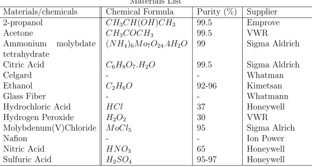
List of Materials and Chemicals
Materials List
Materials/chemicals Chemical Formula Purity (%) Supplier 2-propanol CH3CH(OH)CH3 99.5 Emprove
Acetone CH3COCH3 99.5 VWR
Ammonium molybdate tetrahydrate
(N H4)6M o7O24.4H2O 99 Sigma Aldrich
Citric Acid C6H8O7.H2O 99.5 Sigma Aldrich
Celgard - - Whatman
Ethanol C2H6O 92-96 Kimetsan
Glass Fiber - - Whatmann
Hydrochloric Acid HCl 37 Honeywell Hydrogen Peroxide H2O2 30 VWR
Molybdenum(V)Chloride M oCl5 95 Sigma Alrich
Nafion - - Ion Power
Nitric Acid HN O3 65 Honeywell
Sulfuric Acid H2SO4 95-97 Honeywell
2.2
Experimental Procedures
Overall experimental procedures can be classified into three major parts in this master study. Firstly proposed materials are synthesized, then their morpholog-ical and physmorpholog-ical characterizations are performed by using instrumental analysis techniques. Finally, electrochemical performances involving the application of ac-tive nanostructured composite materials as electrode were tested in Li-O2 battery
cell.
2.2.1
Materials Preparation
Firstly, materials were tried to synthesized with bare MWCNTs. However MWCNT is hydrophobic itself so, homogeneous and well distributed metal ox-ide particles could not obtained in the aqueous media by using bare MWCNTs. Therefore, methods that can attach functional groups on MWCNT’s wall were investigated and utilized methods are given in the further section.
2.2.1.1 Functionalization Process of MWCNTs
In this work three different methods are applied to obtain functional groups on multi-walled carbon nanotubes (MWCNT) in order to grow well distributed metal oxide nanoparticles on the surface due to homogeneous functional spots.
We used H2O2 for the first method. In this treatment, %30 H2O2 and MWCNT
are mixed with specified amounts and stirred on the magnetic stirrer for 5 days at 65oC. In order to define desired functionalization amount, 5ml of mixture was taking with pipette at the 1st, 3rd, and 5th days of treatment and 5ml of H2O2
was added to keep the concentration of mixture constant. All three samples are washed and filtered with di-ionized water. At first they dried in the oven at 110oC
For second oxidization method, only nitric acid is used. MWCNT are treated with HNO3 at 70oC for various synthesis times on the magnetic stirrer. After
that it cooled down to room temperature and diluted with distilled water. Same drying process with H2O2 treatment is applied after this dilution process.
MWCNT were chemically treated by a mixture 3:1 (v/v) of concentrated H2SO4/HNO3 for the final methodo. Although this treatment can modify the
MWCNT surface, it has not disrupted its main structure. Oxidization using strong acids (e.g., mixture of HNO3 and H2SO4) is one typical and widely used
approach to generate defects on the surface of nanotubes. After oxidization, the functional carboxylic acid or hydroxyl groups on CNT have a rich chemistry. Subsequently, such kind of CNT can be treated with a further chemical reaction. For this process, sufficient amount of MWCNT weighted and mixed with HNO3.
H2SO4 is gradually added on this mixture in the ice bath while mixing by hand.
Total mixture stirred at 70oC for 2 hours on the magnetic stirrer. After MWCNT
and acidic mixture cooled down, they are added into the 5% HCl solution and filtered by using di-ionized water until its pH value become neutral. At final step, filtered sample dried in the atmospheric conditions.
2.2.1.2 Solvothermal Synthesis
Many types of materials can be synthesized by using solvothermal method such as metals, ceramics and polymers. In this process, moderate to high tempera-ture (100 to 1000oC) and pressure (1 to 10.000 atm) are used which makes the interactions of materials in the solvent easier during synthesis. It is called hy-drothermal synthesis when water is used as solvent. Various geometries can be obtained such as thin films, nanocrystals and bulk powder by using this process. Moreover, crystal morphology can be controlled by changing the chemical con-centrations, kinetic control and manipulating the supersaturation of solvent. Due to unique nature of the nanocrystals, many solvothermal synthesis method have been performed to obtain required properties and morphologies of nanoparticles over the last decades. This method is particularly suitable for the growth of
large good-quality crystals while maintaining good control over their composi-tion. Also, it is economic, facile and versatile technique in comparison with other techniques. In this study, conventional and microwave solvothermal methods are used to produce our samples.
In conventional method, autoclaves are used as reaction vessels. They are com-monly made from stainless-steel with air-proof seal which should tolerate high pressure and temperatures for long time reaction periods. Most of the solution which are used in solvothermal experiments are steel corroded. Therefore, auto-clave material should be inert with respect to the solvent. In addition protective inserts (mostly teflon) are used to prevent corrosion and they have the same shape with the internal cavity of autoclave. In our experiments, MWCNTs and distilled water are homogenized in the ultrasonic bath. (NH4)6Mo7O24.4H2O and ethanol
mixed on the other side. After stirring, specified amount of HNO3 is added drop
by drop into the molybdenum solution. These two solution are mixed and trans-ferred to the teflon cup and then autoclave was kept in a conventional oven for the preset time and temperature. After reaction is completed, mixture is washed by centrifugation and dried in the oven.
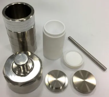
Figure 2.1: The hydrothermal autoclaves used in this master thesis work. The hydrothermal autoclaves used in this work are acid digestion bombs with 100
ml capacity , as is shown in Fig. 2.1. The outer parts are made of stainless steel to seal the polytetrafluoroethylene (PTFE) cup. The temperature can reach up to 230oC and the pressure can reach up to 3 MPa.
Microwave synthesis is the another effective method which was used in this study to obtain desired nanostructures. In the basis, conventional method and mi-crowave synthesis are similar. However, heat energy is transferred electrochemi-cally and quickly through the whole volumetric part while heating is applied as a thermal heat flux for autoclave. Therefore, less overall energy is used and tem-perature can be easily controlled with microwave synthesis. Also, higher temper-atures and pressures can be accessed with microwave reactors while it is difficult with autoclaves. In our experiments, molybdenum precursor (MoCl5) and
reduc-ing agent (citric acid) were mixed with functionalized-MWCNT (FCNT)/distilled water solution while it was stirring. It should be noted that the used weight amounts of carbon material and metal precursor for first synthesis defined as (1:1) ratio. Various combinations of contents are tried and labeling arranged due to this first amounts. Total mixture was loaded into the glass vessel of microwave furnace and transferred through the machine. Synthesis was carried out at 160oC
for 30 minutes by applying 160W power. After synthesis, solution cooled down by air flow. Washing process applied by centrifugation and sample dried in the oven.
Here, the microwave oven used is a Monowave300 microwave system which is provided by Anton-Paar as shown in Fig. 2.2. The maximum power reaches up to 850 W. It has 3 different borosilicate glass vials for reaction volumes from 0.5 mL to 20 mL where reactions take place at temperatures up to 300oC and
pressures up to 30 bar.
For both synthesis methods parameters are modified in order to obtain desired structure and the morphology. Various sythesis temperatures, pressures, chemical concentrations and annealing temperatures were applied to provide better per-formance for the non-aqueous Li-O2 batteries. Moreover, carbon nanofibers were
replaced with FCNTs in the microwave synthesis to see the effects of different carbon materials to the electrochemical and structural properties.
Figure 2.2: Monowave300 microwave system used in this study. 2.2.1.3 Cathode and Electrolyte Preparation
In order to obtain well designed cathode, three different preperation method were utilized in this study as given in the following list:
• Filtration Method: Synthesized solutions are filtered by using glass fiber filter and particles accumulated as a film. Then, this film separated from the surface by the help of tweezers. In some cases, film-like sample could not separated therefore, they used with glass fiber in the battery cell for electrochemical testings.
• Dropping Method: Cathode material is distributed in the isopropanol with ultrasonic bath or tip sonicator and then dropped on the nickel foam as a dropping method. It was not a good method in order to obtain homogeneous distribution of cathode materials on the nickel foam.
• Dipping Method: Nickel foams were dipped into the cathode solution and they stirred in the ultrasonic bath to provide homogeneous distribution of
cathode material and prevent pore clogging of foam. Also while cathode material dropped, the cathode weighted heavier so lighter cathodes were obtained by dipping technique.
All preparation methods have been applied to achieve lighter cathode material, whereat proportionally higher specific capacity.
Bis(trifluoromethane)sulfonimide lithium salt (LiTFSI) and tetraethylene glycol dimethyl ether (4G) which is polar aprotic solvent is used to prepare electrolyte. Firstly, water amount of solvent is reduced by using 4A molecular sieves (Sigma Aldrich), which were regenerated in the tube furnace at 200oC for 3 hours in the
argon atmosphere, for several days. Also lithium salt is dried in the vacuum oven for overnight. After that, they were transferred into the glovebox and 0.5M of solution is prepared in the argon atmosphere. Water amount was measured by Metrohm’s 899 Coulometer for both solvent and final solution, separately.
2.2.2
Cell Assembly
In this study, swagelok type cell is used for all experiments. Cell involves mainly three parts which are upper cap, oxygen tank and bottom cap. While oxygen tank and upper cap is only for filling and purging process, bottom cap is the main part which electrochemical reactions take place.
First of all, battery parts and cathode material are dried in the vacuum oven overnight in order to decrease moisture amount as much as possible and quickly carried into antichamber. Components waited for 30 minutes in the vacuum and filled with argon gas. This refill-purge process repeated two more times and each following vacuums are kept for 3 minutes. After purification step finished, all parts transferred into the glovebox. There is 1 cm2 circular place in the middle
of bottom cap to put anode material but lithium metal did not directly cut and placed in this area. To use anode material providently, it was cut into small pieces and enlarged by rolling. Rolled film-like lithium was placed on the 1 cm2 circular
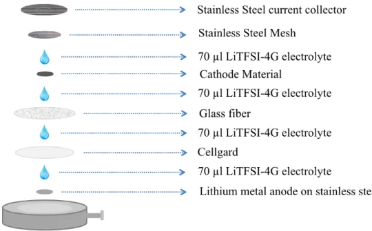
Figure 2.3: Schematic Shown of Non-Aqueous Li-O2 Battery Preparation stainless steal and excess parts were cut by the help of nippers. Prepared anode put downed and 70 µl electrolyte dropped on it. Cellgard, glass fiber and cathode material are placed, respectively and adding electrolyte is repeated for each step as shown in the Figure 2.3. After stainless steal mesh and current collector are put on other parts oxygen tank and upper cap closed carefully and screwed firmly. At last step, assembled battery cell waited for 7 hours and filled with oxygen gas in order to star electrochemical battery testing.
2.2.3
Characterization Methods
Physical and structural characterizations of synthesized materials are carried out by using X-Ray Diffraction, X-Ray Photoelectron Spectroscopy, Scanning Elec-tron Microscopy and Transmission ElecElec-tron Microscopy. Electrochemical testings are performed by using galvanostatic discharge-charge testing. In this section, all characterization methods are briefly introduced and sample preparations for each methods are given.
2.2.3.1 X-ray Diffraction (XRD)
X-ray powder diffraction (XRD) is a rapid analytical technique primarily used for phase identification of a crystalline material and can provide information on unit cell dimensions. XRD patterns are unique to crystalline phases and can be used as a fingerprint for phase identification in a sample. In this study, XRD measurements were carried out using a PANalyticals X2Pert Pro diffractometers diffractometer employing Cu-K radiation ( = 1.5406 A) between 5 to 85 degrees and equipped with a GaliPIX-3D detector. Samples were grinded and powder form of them placed on the sample holder for testing.
2.2.3.2 X-ray Photoelectron Spectroscopy (XPS)
X-ray photoelectron spectroscopy (XPS) is a surface-sensitive quantitative spec-troscopic technique that measures the elemental composition at the parts per thousand range and can determine the empirical formula, chemical state and electronic state of the elements that exist within a material. XPS experiments in this thesis were carried out on a Thermo Scientific K-Alpha instrument using aluminum Kα X-ray radiation. Powder forms of samples were just sticked on the holder with copper tape. Discharged-charged cathodes were washed and prepared in the glovebox then carried to the XPS insturement as quick as possible.
2.2.3.3 Scanning Electron Microscopy (SEM)
Electrons are focused as beam and scan the sample in order to get image with SEM which is a type of electron microscope. Sending electrons interact with sample atoms and produce various detectable signals. These signals contains lots of in-formation about morphology, topography and composition of the sample surface. In this master study, SEM measurements were carried out using FEI’s Quanta-200F instrument. For sample preparation, powder samples firstly dispersed in the acetone and dropped on the nickel plate. After they dried, they are coated
with Au-Pd with using precision etching coating system by Gatan (Model862). Coated samples were transferred into the machine and characterized.
2.2.3.4 Transmission Electron Microscopy (TEM)
TEM is a microscopy technique in which a beam of electrons is transmitted through an specimen, interacting with the specimen as it passes through. Con-versly with SEM, atomic scale magnification is possible. While nanoparticles were synthesized in this study, to observe the crystal size and their structures we need to use TEM. Powder samples were dispersed in the ISP and dropped on the TEM grid to prepare specimen. In this work, TEM images were collected using a FEI’s Tecnai G2 instrument in the TEM and STEM modes with various magnifications.
2.2.3.5 Galvanostatic Charge/Discharge Testing
The capacity and cycling performance of the Li-O2 batteries were investigated by galvanostatic charge-discharge testing at various current densities. All tests were carried out on a Land CT 2001-A. Firstly current density determined due to cathode area but after cathode weight optimized, current rates applied due to weight of cathode material. All experiments applied between 2 to 4.5 voltage range and their cycling performances also carried out up to 20 cycle. Capacity limitation was not used for any galvanostatic testing. All result are obtained from full charge-discharge of batteries.
Chapter 3
Results and Discussion
In this chapter, all results are given in the order of synthesized cathode materials. Structural, morphological and electrochemical testing results were not separated into parts. The motivation of this study is to produce effective catalyst materials for Li-O2batteries in order to enhance their performance and decrease their charge
and discharge overpotentials. As it is mentioned in the introduction part carbon nanotube is the best candidate for base material which would be modified with metal oxide catalyst. Therefore, we performed galvanostatic testing of pristine CNT to obtain reference data for following experiments.
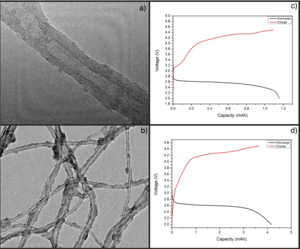
Firstly, molybdenum oxide nanoparticles are produced on the CNTs by using au-toclave technique. Morphological comparisons and galvanostatic results of pris-tine CNT and CNT@MoOx are given in the Figure 3.1. As shown in the Fig. 3.1c, MoOx particles are accumulated on the surface but they are not homoge-neously distributed. In the darker parts, metal particle concentrations is more than the rest of the structure. There are some small particle-like formation on the pristine CNT and they might be misleading. The reason of these formations might be contamination or residuals from the organic solvent which is used for TEM sample preparation.
Figure 3.1: a,b) TEM images and c,d) galvanostatic discharge-charge results of pristine CNT and CNT@MoOx samples, respectively.
To see the effect of molybdenum oxide particles on the electrochemical perfor-mance, galvanostatic discharge-charge testing is applied and result are given in the Fig. 3.1 (c-d) for pristine CNT and CNT@MoOx. Unfortunately results are almost same, overpotential is slightly better than CNT and also higher capacity is obtained but this capacity is not specific capacity so the reason of these difference might be the amount of the cathode material.
According to charge-discharge testing, accumulating molybdenum oxide provide better overpotential. However, oxide particles were not well distributed. The reason of that may be hydrophobic nature of bare CNT. It prevents to obtain homogeneous mixtures during synthesis and also surface of CNTs are not capable to attach metal particles homogeneously. When they start to nucleate on some regions, other metal oxide particles thermodynamically prefer to grow on them.
Therefore, MWCNT surface was functionalized in order to create oxygen func-tional groups on to the surface. These funcfunc-tional groups may be starting point for nucleation process thus, homogeneous distribution could be obtained. This is important because interaction between cathode material and catalyst material should be as high as possible in order to provide better activity.
Functionalization of MWCNT Surface
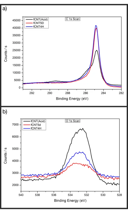
As mentioned in the experimental chapter, three different functionalization tech-niques were applied in order to create oxygen functional groups on the carbon nanotube walls. Due to hydrophobic nature of the CNTs, it was difficult to obtain well distributed solution while doing synthesis and also facilitate the interactions between metal atoms and CNTs were necessary to provide better formation metal oxides on the surface. In order to investigate the oxygen functional groups after treatments, XPS measurement were carried out. C 1s and O 1s scans of all three functionalization methods were compared in the figure 3.2(a,b), respectively. At first, peaks of the H2O2 treated sample which is fCNT5D was examined.
According to C 1s scan, only C-C bonding for unmodified carbon materials was observed at the 284.4 eV binding energy. This sp2 hybrid carbon bonding peak is
not broadening and it shows that there is no significant functional group on the CNT surface. Only π −π∗ shake-up is responsible from the very small broad peak at 291.5ev and it should not be confusing with functional groups. [58] Normally, there should be no peak for oxygen after O 1s scan if functionalization were not happened but O1s peak confirmed the presence of some carboxylic functions onto the CNT surface at 533.2 eV. It proves that less amount of functional groups exist in the structure. The intensity of carbon peaks are very intense. That’s why this carboxylic group is not observable on the C peak.
Second functionalization trail was the HNO3 treatment. This treatment applied
for 4 hours and sample labeled as fCNT4H. Unfortunately, at C 1s scan of treated CNTs, no functional peak is seen. On the other hand, intensity of O 1s peak slightly increased. It may suggest that some functional carboxylic groups were also attached the surface of CNTs but even if their percentage is higher than
Figure 3.2: Comparison XPS of a) C 1s and b) O 1s signals from functionalized nanotubes by three different treatment.
fCNT5D sample since intensity is higher, possibly it was not required amount. At last, the most effective method is applied for functionalization which is con-centrated acid treatment involves H2SO4, HNO3 and HCl as mentioned in the
experimental section. It can be clearly seen that MWCNTs showed a main peak at 284.4 eV, attributed to the graphitic structure in agreement with recent pho-toemission studies on MWCNTs. Moreover, a peak at 285.5 eV was attributed to defects on the nanotube structure, whereas the peaks at 286.7, 288.3 and 290 eV, correspond to carbon atoms attached to different oxygen-containing moi-eties which are (C-O), (-O-C=O) and carbonates, respectively. Also, XPS O1s peak confirmed the presence of some carboxylic and hydroxyl functions onto the CNT surface at 533.2 eV and 531.9 eV, respectively. [59] Consequently, required functional groups were obtained by using concentrated acid treatment. For next step, molybdenum oxide was tried to form on the these treated surfaces by using microwave synthesis method and effect of modification is investigated.
First functionalization treatment was H2O2 treatment and electrochemical testing
of them performed before doing their XPS measurements. 5 days treated fCNTs were chosen because it has been considered that desired amount of functional groups may be obtained if treatment process was hold for longer times.
After functionalization process, microwave synthesis technique was carried out due to its advantages as mentioned in the experimental chapter. 5 days treated fCNTs used for synthesis and MoOx particles were accumulated as shown in the (Figure 3.3). fCNTs were totally covered with molybdenum oxide nanoparticles. It is almost impossible to see nanotubes clearly, therefore TEM images could only captured from the edges of the compact sample. Figure 3.3b shows that molybdenum oxides formed as very small and uniform nanoparticles on the sur-face of fCNT but they plugged all mesapores of cathode structure which may prevent oxygen and electrolyte transfer. Although metal particles look like form-ing amongst themselves, closer look proves that they are attached to the fCNT surface but their interactions may cause entanglement of carbon nanotubes. This results indicates that desired morphology could not been achieved by using H2O2
Figure 3.3: a,b) TEM images of fCNT@MoOX sample for lower and higher magnifications.
obvious. H2O2 does not work to attach functional groups on CNT surface, thus
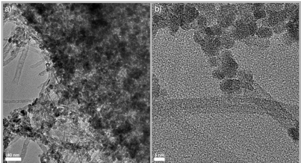
expected morphology could not obtained. Therefore, concentrated acid treatment was applied even it was very dangerous to perform.
TEM and STEM images of as synthesized fCNT@MoOx sample with concen-trated acid treated fCNT are given in the (Figure 3.4a,b), respectively. Both figures illustrates that molybdenum oxide particles formed directly on the fCNT surface. Although particles looks like well distributed, half of the carbon nan-otube surface are metal oxide free, whereas smaller and totally covered metal oxide particles were desired in order to obtain film-like discharge product due to ease of decomposition than bulk structure. Also totally coated fCNT surface could be beneficial because it can prevent parasitic reactions which may happen between carbon material and electrolyte but none of them could achieved. Figure 3.4c presents the XPS spectrum of the Mo 3d. As can be seen from that figure, the 3d profile can be fit by two pairs of Gaussian peaks. The most intense pair is centered at 235.8 and 232.7 eV which are, respectively, the binding energy of elec-trons in the 3d3/2 and 3d5/2levels of molybdenum in the Mo+6 valence state. The
other pair is centered at 234.6 and 231.6 eV corresponding to the binding energy of electrons in the same 3d levels, but in Mo+5 valence state. It was concluded
Figure 3.4: a,b) TEM images of as synthesized fCNT@MoOx sample with con-centrated acid treated fCNT c) XPS spectrum of the Mo 3d scan of fCNT@MoOx cathodes.
that the Mo atoms were in mixed valence states, Mo+6 and Mo+5 [60, 61].
Figure 3.5: Galvanostatic charge-discharge test result of fCNT@MoOx cathode material.
For the next step, galvanostatic discharge/charge tests were conducted to further study the electrochemical activity of fCNT@MoOx electrode as shown in (Figure 3.5). The batteries were cycled within the potential window of 2-4.5 V (vs Li+/Li)
at currents equivalent to the current densities of 0.1 mA/cm2 which is based on the cathode surface. Over half of the first charge process was conducted under the potential of 3.5 V, indicating good OER activity of MoOx particles. With increasing of cycle numbers, charge overpotential significantly increased, however both charge and discharge capacity slightly decreased which is demonstrates good capacity retention of fCNT@MoOx cathode. As mentioned before metal oxide distribution on the fCNT surface is inhomogeneous and catalyst materials are only effective at the region that they accumulate. Therefore, high voltage values were needed to decompose main discharge product on the carbon regions so electrolyte decomposition inevitable. Due to electrolyte decomposition some insulator side products such as Li2CO3 forms on the cathode surface which blocks catalyst
![Figure 1.1: Comparison between the specific energy density of different battery technologies.[Ref.7]](https://thumb-eu.123doks.com/thumbv2/9libnet/5843649.119797/17.918.296.663.589.828/figure-comparison-specific-energy-density-different-battery-technologies.webp)
![Figure 1.2: Schematic of the four different architectures of Liair battery. [Ref.11]](https://thumb-eu.123doks.com/thumbv2/9libnet/5843649.119797/21.918.302.656.167.482/figure-schematic-different-architectures-liair-battery-ref.webp)
![Figure 1.3: Working principle of a rechargeable Li-O2 battery.[Ref.16]](https://thumb-eu.123doks.com/thumbv2/9libnet/5843649.119797/22.918.354.618.176.386/figure-working-principle-rechargeable-li-o-battery-ref.webp)