MULTI-SLM HOLOGRAPHIC DISPLAY SYSTEM WITH PLANAR
CONFIGURATION
Fahri Yaras¸, Hoonjong Kang, Levent Onural
Bilkent University
Department of Electrical and Electronics Engineering
TR-06800 Ankara, Turkey
[email protected], [email protected], [email protected]
ABSTRACT
Holographic display system that uses six phase-only spatial light modulators (SLMs) performs holographic reconstructions from the phase-hologram of a point cloud that is extracted from 3D object. The SLMs are tiled as a three by two matrix on a virtual planar surface. The alignment is successful and the display system generates large holographic reconstructions. The proposed system can be used either to obtain reconstructions of large objects with a narrow field of view or reconstructions of smaller objects with a broader field of view. Therefore, since field of view is broader for smaller objects, observer has the flexibility to move around the reconstruction within a larger angle. This flexibility increases the motion parallax and as a consequence it increases the qual-ity of 3D perception. Results show that even with three SLMs in horizontal direction the 3D perception is significantly increased. Experimental results are satisfactory.
Index Terms — wide holographic displays, spatial light mod-ulators, phase holograms, three-dimensional displays, computer generated holography
1. INTRODUCTION
Narrow viewing angle of the spatial light modulators (SLMs) is a significant problem in holographic display technologies and there-fore in 3DTV applications. Due to the pixelated structure of the SLMs the maximum diffraction angle is limited by the pixel peri-ods [1, 2, 3, 4, 5, 6, 7, 8, 9]. A few micrometers of pixel periperi-ods may not be sufficient for 3D viewing as comfortable as in analog holography. In addition, since the size of the commercially avail-able SLMs is rather small, the field of view is quite limited. There-fore, the viewer can not move in a comfortable manner while ob-serving the reconstructions. Therefore, the motion parallax, which is a depth cue, is not sufficient. Furthermore, as a consequence of limited field of view, reconstructed object size is rather small.
To increase the field of view Maeno et al. reported a wide holographic display system [10]. In this system they align five transmission type liquid crystal SLMs side by side horizontally. Therefore the field of view in the horizontal direction is increased. Additionally, they discard the vertical parallax and put a lenticu-lar sheet on the vertical image plane. Moreover, Springer et al. proposed a different tiling method which uses both electrically
This work is supported by EC within FP7 under Grant 216105 with the acronym Real 3D.
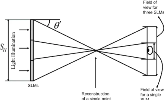
L ig h t il lu m in at io n Field of view for three SLMs Reconstruction of a single point H
S
Field of view for a single SLMθ
′
SLMsFigure 1. Increase in the field of view when multiple SLMs are used
and optically addressed SLMs [11, 12, 13]. In their setup, high-speed electrically addressed SLM drives 25 optically addressed SLMs, which are tiled in a five by five matrix format, in a time-multiplexing mode. In a recent work by Hahn et al., a curved array of SLMs is used to obtain a large field of view [14].
One way to enhance the 3D viewing comfort is to increase the hologram size (i.e. SLM size). Therefore, we propose and implement a multi-SLM holographic display system. The holo-graphic display consists of six high-definition phase-only SLMs which are tiled in three by two fashion. After aligning them by us-ing some optical elements and high precision stages we generate a large computer generated hologram. The generated large holo-gram is divided into six parts to match the SLM array. With the help of a video driver, the computed holograms are then loaded to the SLMs. We observed the reconstructions by illuminating the SLM matrix with a plane wave. Different from Ref.[10], we do not discard the vertical parallax; there are no lenticular sheets or any other optical elements. As a result of this experiment, we have shown that multiple SLMs can be used to increase field of view. With the help of the large field of view, observer can look at the reconstructions binocularly and see a ghost-like 3D image floating in the space. Since we use an LED as a light source, reconstruc-tions can be observed by the naked eye.
2. ADVANTAGES OF USING MULTIPLE SLMS
Due to the pixelated structure of the SLMs, the spatial frequency that can be supported by them is limited. Having that maximum spatial frequency of the hologram, we can calculate the local
max-978-1-4244-6379-4/10/$26.00 ©2010 IEEE
imum diffraction angle for Shannon recovery as:
θmax= sin−1(λfmax), (1)
where;
fmax= 1
2∆p, (2)
and∆pis the pixel period of the SLM. By assuming θ′< θmax. Fig.1 shows the reconstruction of a single point in the reconstruc-tion plane and how the field of view increases when multiple SLMs are used in planar configuration. Due to the small size of a single SLM, field of view is not sufficient to observe parallax in the holo-graphic reconstructions. On the other hand, when the number of SLMs increases, field of view also increases substantially. Fur-thermore, when multiple SLMs are used, hologram size increases, and as a result, an increase in the reconstruction size is expected (see Fig.2). When the number of SLMs that are used side by side is N , available space for the reconstruction can be calculated as:
SR= N × SSLM+ 2DRtan(θmax), (3) where SSLM is the size of a single SLM and DRis the recon-struction distance. For each additional SLM, reconrecon-struction space increases. In addition, multiple SLM configuration has a
signifi-L ig h t il lu m in at io n Reconstruction space for a single SLM H S max
θ
maxθ
maxθ
maxθ
Reconstruction space for three SLMsR
D
Figure 2. Increase in the reconstruction space when multiple SLMs are used
cant effect on the quality of the reconstructed image. Fig.3 shows how the number of pixels that are contributed to the reconstruc-tion of a single point increases when the number of SLMs is in-creased. In the figure, P denotes a point where all the pixels can contribute to the reconstruction. Although the reconstructed ob-jects in Fig.3 (a) and (b) are the same size and located at the same position with respect to the observer, their quality may differ since the number of pixels that are contributed to the reconstructions is different. The quality assessment can be correlated here with the
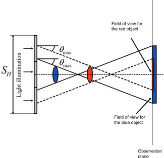
space-bandwidth product (SBP). We assume that the bandwidth is limited by the maximum band supported by the SLM; therefore, the quality of the reconstructions is determined by the number of pixels contributed to the reconstructions (space). Larger the num-ber of SLMs, higher the quality is obtained in the reconstruction. Moreover, if the object gets closer to the SLM, although not all pixels are contributed to the reconstruction, field of view increases (see Fig.4). L ig h t il lu m in at io n H
S
Light illumination SLM HS
D′
D′
maxθ
maxθ
P
P
(a) (b) ObserverD ′
′
ObserverD ′
′
Figure 3. Increase in the quality when multiple SLMs are used. Only those SLM pixels within the dotted cone contributed to the image.
3. SETUP AND HOLOGRAM GENERATION
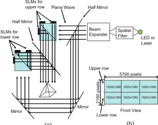
In our experiment, we have used six HoloEye HEO 1080P phase-only spatial light modulators [15]. Fig.5 (a) shows the top view of the setup. The light that emerges from the source, which is a LED, first passes through a spatial filter to increase the spatial coherence. After that with the help of a beam expander a plane wave is obtained. Then it is directed to the SLMs by mirrors, half mirrors and beam splitters. Phase holograms that are loaded to the SLMs are tiles of a large hologram which is calculated by a Fresnel based approach [16]. Each SLM has1920 × 1080 pixels and are tiled as a three by two matrix on a virtual planar surface (see Fig.5 (b)). Therefore the large hologram size is5760 × 2160.
L ig h t il lu m in at io n H
S
maxθ
maxθ
Observation plane Field of view for the red objectField of view for the blue object
LED or Laser Spatial Filter Beam Expander Plane Wave SLMs for upper row SLMs for lower row Half Mirror Mirror Mirror Upper row Lower row Front View (a) (b) Half Mirror 5760 pixels 2 1 6 0 p ix e ls 1920x1080 1920x1080 1920x1080 1920x1080 1920x1080 1920x1080
Figure 5. (a) Top view of the setup (b) Front view of the tiled SLMs
4. EXPERIMENTAL RESULTS
The point cloud of a 3D model that is used in our experiments is a square pyramid (see Fig.6). After generating the large hologram of the model, the optical reconstruction is recorded by a camera. Reconstruction is 0.5 m away from the SLMs. Fig.7 shows the recorded optical reconstructions. Fig.7 (a) shows the left view of the reconstructed 3D object and (b) and (c) show front and right views, respectively. We can conclude that when the hologram size increases field of view also increases, as expected. Therefore, if we use a larger number of SLMs we can improve the parallax and thus the 3D perception. There are several wide holographic display systems in the literature as mentioned in Sec.1 and, exper-imental results show that the proposed holographic display system is also satisfactory.
5. CONCLUSION
The system has six phase-only spatial light modulators and they are tiled as a three by two matrix on a virtual planar surface. The alignment is successful and the display system generates large holographic reconstructions. It can be used either to obtain re-constructions of large objects with narrow field of view or recon-structions of smaller objects with broader field of view. There-fore, since field of view is broader for smaller objects, observer has flexibility to move around the reconstruction within a larger angle. This flexibility increases the motion parallax and as a con-sequence it increases the quality of 3D perception. Results show that even with three SLMs in horizontal direction the 3D percep-tion is significantly increased. Images that are recorded in differ-ent lateral positions show the parallax. Experimdiffer-ental results are satisfactory and it is observed that the proposed system can be used as a holographic display.
6. REFERENCES
[1] M. Kovachev, R. Ilieva, P. Benzie, G. B. Esmer, L. Onu-ral, J. Watson, and T. Reyhan, “Holographic 3DTV dis-plays using spatial light modulators,” in Three-Dimensional
Television - Capture, Transmission, Display,H. Ozaktas and L. Onural, eds., pp. 529–555, (Springer, 2008).
Figure 6. Rigid 3D model of a square pyramid
(a) (b) (c)
Figure 7. Optical reconstructions: (a) left, (b) front and (c) right view.
[2] F. Yaras¸, H. Kang, and L. Onural, “Real-time phase-only color holographic video display system using LED illumi-nation,” Appl. Opt., vol. 48, no. 34, pp. H48–H53, 2009. [3] F. Yaras, M. Kovachev, R. Ilieva, M. Agour, and L.
Onu-ral, “Holographic reconstructions using phase-only spatial light modulators,” in 3DTV Conference: The True Vision
-Capture, Transmission and Display of 3D Video, pp. PD–1– PD–4, 2008.
[4] F. Yaras and L. Onural, “Color holographic reconstruction using multiple SLMs and LED illumination,” in Proc. SPIE., vol. 7237, p. 72370O, 2009.
[5] F. Yaras¸, H. Kang, and L. Onural, “Real-time color holo-graphic video display system,” in 3DTV Conference: The
True Vision - Capture, Transmission and Display of 3D Video, IEEE, 2009.
[6] F. Yaras¸, H. Kang, and L. Onural, “Real-time multiple SLM color holographic display using multiple GPU acceler-ation,” in Digital Holography and Three-Dimensional
Imag-ing, OSA, p. DWA4, 2009.
[7] H. Kang, F. Yaras¸, and L. Onural, “Graphics processing unit accelerated computation of digital holograms,” Appl. Opt., vol. 48, no. 34, pp. H137–H143, 2009.
[8] H. Kang, F. Yaras¸, L. Onural, and H. Yoshikawa, “Real-time fringe pattern generation with high quality,” in
Dig-ital Holography and Three-Dimensional Imaging, OSA, p. DTuB7, 2009.
[9] H. Kang, F. Yaras¸, and L. Onural, “Quality comparison and acceleration for digital hologram generation method based on segmentation,” in 3DTV Conference: The True Vision
- Capture, Transmission and Display of 3D Video, IEEE, 2009.
[10] K. Maeno, N. Fukaya, O. Nishikawa, K. Sato, and T. Honda, “Electro-holographic display using 15mega pixels LCD,” in
Proc. SPIE., vol. 2652, pp. 15–23, 1996.
[11] C. Slinger, P. Brett, V. Hui, G. Monnington, D. Pain, and I. Sage, “Electrically controllable multiple, active,
computer-generated hologram,” Opt. Lett., vol. 22, no. 14, pp. 1113–1115, 1997.
[12] M. Stanley, R.W. Bannister, C.D. Cameron, S.D. Coomber, I.G. Cresswell, J.R. Hughes, V. Hui, P.O. Jackson, K.A. Milham, R.J. Miller, D.A. Payne, J. Quarrel, D.C. Scatter-good, A.P. Smith, M.A.G. Smith, D.L. Tipton, P.J. Watson, P.J. Webber, and C.W. Slinger, “100-megapixel computer-generated holographic images from active tiling: a dynamic and scalable electro-optic modulator system,” in Proc.
SPIE., vol. 5005, pp. 247–258, 2003.
[13] C.W. Slinger, C.D. Cameron, S.D. Coomber, R.J. Miller, D.A. Payne, A.P. Smith, M.G. Smith, M. Stanley, and P.J. Watson, “Recent developments in computer-generated holography: toward a practical electroholography system for interactive 3D visualization,” in Proc. SPIE., vol. 5290, pp. 27–41, 2004.
[14] J. Hahn, H. Kim, Y. Lim, G. Park, and B. Lee, “Wide view-ing angle dynamic holographic stereogram with a curved ar-ray of spatial light modulators,” Opt. Express, vol. 16, no. 16, pp. 12372–12386, 2008.
[15] “http://www.holoeye.com/,” .
[16] J. W. Goodman, Introduction to Fourier Optics, McGraw-Hill, New York, 1996.