Comput. & Graphics Vol. 14, Nos. 3/4, pp. 491-500, 1990 0097-8493/90 $3.00 + .00
Printed in Great Britain. feb 1990 Pergamon Press plc
Technical Section
F R E E - F O R M SOLID M O D E L I N G U S I N G D E F O R M A T I O N S
UGUR GIDDOKBAY and Bt0LENT (~ZGCI~
Bilkent University, Department of Computer Engineering and Information Sciences, Ankara, Turkey Abstract--One of the most important problems of available solid modeling systems is that the range of shapes generated is limited. It is not easy to model objects with free-form surfaces in a conventional solid modeling system. Such objects can be defined arbitrarily, but then operations on them are not transparent and complications occur. A method for achieving free-form effect is to define regular objects or surfaces, then deform them. This keeps various properties of the model intact while achieving the required visual appearance. This paper discusses a number of geometric modeling techniques with deformations applied to them in attempts to combine various approaches developed so far.
1. I N T R O D U C I ' I O N
A system for deforming three-dimensional models to obtain objects with free-form surfaces is explained in this paper. The system is implemented using C lan- guage [ 8 ] on a Unix* workstation environment. In the implementation of the system, care has been taken to include user interface facilities to simplify the usage [ 7 ]. In advanced C A D / C A M applications, designers need to model solid objects with complex surfaces [ 9 ]. Objects whose surfaces are free-form defy description in terms of analytical surfaces such as planes, cones, spheres, or toroids[4]. There are various approaches to model objects with flee-form surfaces in a solid modeling system.
One approach uses Boolean operations on arbitrary free-form surfaces. To implement Boolean operations, the computation of intersecting curves between two different free-form surfaces is required. This takes a long computation time since intersection algorithms compute points iteratively and perform some type of curve fitting that yields an approximate intersection curve. Because of this, the interpolating curve will never lie exactly on both surfaces. Consequently, intersection algorithms are unreliable.
The second approach involves generating free-form surfaces from a polyhedron. This approach uses rounding operations on polyhedral objects for inte- grating solid modeling and free-form surface model- ing[5]. Since complex calculations are not needed, computation time and reliability are not problems. However, there are several restrictions in the range of shapes generated.
Another approach to model free-form surfaces is based on parametric polynomial functions [ 6 ]. This is a unified approach, and geometric operations can be performed with equal facility on simple primitives and complex sculptured geometries by using it. This ap- proach combines a number of parametric polynomial geometry representations, such as Brzier, Coons, B- spline into a unified modeling system that is capable of interchanging between these representations through mathematical transformations.
A new approach, deformations, is similar to the sec- * Unix is a trademark of AT&T Laboratories.
ond approach in the sense that both provide methods of changing the existing models to create irregular classes of objects. Deformations, first introduced by Alan Barr[2], are a highly intuitive and easily visu- alized set of operations. Deformations allow the user to treat a solid as if it were constructed from a special type of topological putty or clay, which may be bent, twisted, tapered, compressed, expanded, and otherwise transformed into a final shape. Deformations can be incorporated into traditional C A D / C A M solid mod- eling and surface patch methods, reducing the data storage requirements for simulating flexible geometric objects, such as objects made of metal, fabric, or rubber. Without deformations, to simulate an irregular object, one has to save every point on the object. However, one can create a regular object and then apply defor- mations to it to create an irregular object with much less data.
The system currently uses superquadric objects and Brzier surfaces to model regular classes of objects. There are two main approaches used to deform solid geometric models:
• Regular deformations [ 2 ];
• Free-form deformations (FFD) technique [ 10 ]. Our system combines these two approaches for de- forming regular classes of objects to create objects with free-form surfaces. Both deformation techniques can be applied hierarchically and interchangeably in our system. The combination seeks to offer benefits of both regular deformations and FFD technique.
2. MODELING IN OUR SYSTEM
In the implementation of the system, Superquadrics and Brzier Surfaces are used to model regular classes of objects. They are explained briefly with some ex- amples in the following sections for completeness.
2.1. Superquadrics
One long-term goal of computer graphics and nu- merical methods for three-dimensional design is a uni- fied mathematical formalism. Such a unified mathe- matical formalism for geometric representation and computation provides a natural base for a geometric modeler of considerable versatility and robustness [ 6 ]. 491
492 UOUR GODOKBAY Superquadric objects show potential to achieve this goal [ 1 ]. The superquadric objects are a new collection of smooth parametric objects producing a new spec- t r u m of flexible forms. The chief advantage of super- quadrics is that they allow complex solids a n d surfaces to be constructed a n d altered easily by changing a few interactive parameters. The superquadrics family con- sists of mainly superquadric ellipsoids, toroids, hyper- boloids o f one piece, a n d hyperboioids o f two pieces. These shapes differ from the corresponding quadrics in the exponent of their terms. The exponents o f their terms, which are two for the quadric shapes, are re- placed by an arbitrary positive number. By changing the exponent of the terms, the shapes can be rounded, pinched, a n d can have different properties in different sections.
Superquadrics can be defined by either nonpara- metric or parametric equations. O u r i m p l e m e n t a t i o n uses parametric equations to generate superquadrics since generation of surface points is easier with this method.
The mathematics used to define superquadrics can be summarized as follows[l]. Given are two two-di- mensional curves
Lh2(~)J'
~o < ~ < ~ , ,
a n d
r e ( r / ) =
fm,(r/)]
_
Lrn2(r/)
j
, r/o < '7 -< r/,.The spherical product x = m ® h of the two curves is a surface defined as
[ m,(r/)h,(w) ]
_x(r/, o.,) = ] m , ( r / ) h 2 ( o , ) / ,
Lm2(r/)
J
r/o ~ r/ ~ r/]Geometrically, h(w) is a horizontal curve vertically modulated by m(r/); m~ (r/) changes the relative scale o f h, while m2(r/) raises a n d lowers it. ,7 is a north- south parameter, like latitude, whereas co is an east- west parameter, like longitude. Spherical product sur- faces can be rescaled by a separate vector a = [a~, a2, a3 ] r where T denotes the transpose.
Position vectors for different types of superquadric objects follow [ 1 ].
2.1. I. Position vector of surface for superellipsoids."
el ~2
F a , C . C ~ ]
x_(r/, ,o) = l a2C;,S~ l ,
L
aaS~'
J
71" 71" - - - - < r / ~ 2 --2
- - ~where (7, = cos(r/), a n d S, = sin(,/).
and BOLENT OZGO¢
2. i.2.
Position vector of surface for superhyperboloids
of one piece."
x(r/, o~) = aj sec r/C~ ~1 c2 a2sec r/S~ . aatan `~ r/ - - < r / < - 2 22.1.3.
Position vector of surface for superhyperboloids
of two pieces."
x ( r/. o~ ) 7r 71- - - - - < r l < 2 g r alsec~l r/ seC'2°~ ] 71" 71"= Ja2sec',r/tan'2,0j,
- ~ < ~ < ~(piece 1)
k a3tan" 7/7r
37r
< o~ < -~- (piece 2)2.1.4.
Position vector of surface for supertoroids:
['al(a4
+ C~I)C~]
- T r -~ r / - ~ ~"X(r/, oo) = [ a 2 ( a 4 -I- c : , ) s w I ,
k
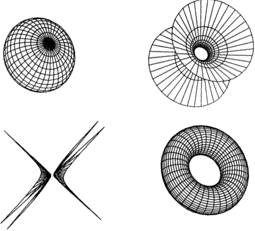
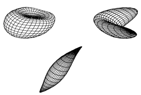
a3Si t j - r _< o~ < rWireframe examples of superquadric objects from our system are shown in Fig. I, and superquadric el- lipsoids with different exponents are shown in Fig. 2. 2.2.
B#zier surfaces
For an arbitrary curve, it may be difficult to devise a single set of parametric equations that completely defines the shape of the curve. However, a n y curve can be approximated by using different sets of parametric functions over different parts of the curve. Since finite degree polynomials are, in m a n y respects, ideal forms for representing and approximating functions, they are used to form these approximations. The smoothness of a curve from one section to another can be described in terms of curve continuity between sections [ 3 ].
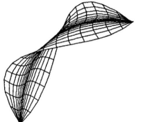
To define a curve or surface in design applications, a set o f control points indicating the shape of the curve or surface is interactively specified. Brzier formulated a method for displaying curves specified with control points using the Bernstein polynomial basis. A useful feature of Bernstein basis is its convex-hull property, which means that any curve defined using it smoothly follows the control points without erratic oscillations. F o r m u l a t i o n of Brzier Surfaces can be found in [ 3 ]. Fig. 3 shows two Brzier Surfaces generated by our system.
3. DEFORMATIONS
Since the primary goal of our system is to create the free-form objects a n d scenes that the user desires, we have to supply the user with the operations that can be used to achieve this goal. We have implemented deformations for this purpose. Two deformation tech-
Free-form solid modeling
Fig. 1. Superquadric ellipsoid, hyperboloid of one piece, hyperboloid of two pieces, and toroid.
493
CAG 14:3/4-I
l
494 UGUR GCDt3KBAY and Bf3LENT OZGC" C
Fig. 3. Two B~zier surfaces.
niques are used in the implementation. Regular de- formations [ 2 ] simulate twisting, bending, tapering, or similar transformations of geometric objects. Free-form deformation technique [ l 0 ] is mainly developed to de- fine the solid geometric model of an object bounded by free-form surfaces, and to sculpt it further with flex- ibility and freedom. Both of these techniques have ad- vantages and disadvantages.
Although results of FFD can be guessed according to the movement of control points, desired objects can be obtained by trial and error. However, regular de- formations are well defined and their results are straightforward. On the other hand, using FFD as a free-form modeling technique is better than using reg- ular deformations due to the generality of it.
A very important disadvantage of FFD is the speed of the deformations since operations on trivariate Bernstein polynomials are very costly. It can be made faster by converting trivariate Bernstein polynomials to standard power basis polynomials. However, this operation also takes a fair amount of time.
The speed of deforming an object with FFD tech- nique also depends on the number of control points. A deformation defined by larger number of control points can cause the deformed shape to follow the con- trol points more closely than for lower degree defor- mations[ 1 l]. This produces better results, but at the expense of slowing down the operations. Regular de- formations are very fast compared to FFD technique. These two approaches have some common prop- erties.
• Both approaches can be applied hierarchically to create complex objects from simpler ones,
• Both approaches can be applied to any solid mod- eling scheme.
• Both approaches compute the new x, y, z coordinates of a point as polynomial functions of the original x, y, z coordinates of that point.
Another important issue is that regular deformations can also be performed using FFD since it is a method for deforming three-dimensional objects in a free-form manner. However, using F F D to make twisting, bend- ing, and tapering operations brings some undesired ef-
fects. For example, when an object is bent using FFD technique, the result will not be as predictable as when the same object is bent using regular deformations.
Due to the reasons stated above, our system com- bines the two approaches to alleviate the problems of them, and to offer the benefits to the user. When regular deformations are suitable for modeling an object, he or she may use them to gain in speed. When they are not sufficient for modeling an object, either FFD tech- nique can be used, or both of the techniques can be applied hierarchically and interchangeably. The two deformation techniques are explained briefly with some examples in the following sections for completeness.
3.1. Regular deformations
A globally specified deformation of a three-dimen- sional solid is a mathematical function _F which ex- plicitly modifies the global coordinates of points in space. Mathematically, it can be represented by the equation _X = _F(x) where _ represents the point in the undeformed solid, and X represents the points in the deformed solid [ 2 ]. Each of the regular deformations are explained in detail in the following sections.
3.1.1. Tapering. Tapering is making an object become
gradually narrower toward one end of it. Mathemati- cally, it differentially changes the length of the two global components without changing the length of the third.
To do a tapering operation along the z-axis, one should choose a tapering function depending on the z-coordinates of the points. When the tapering function
f ( z ) = 1, the portion of the deformed object is un- changed; the object increases in size as a function of z when f ' ( z ) > 0 and decreases in size w h e n f ' ( z ) < 0. The object passes through a singularity a t f ( z ) = 0 and becomes everted w h e n f ( z ) < 0. Global tapering along the z-axis is given by the following equations:
r = f ( z ) Y = r x
Y = ry Z = z .
Free-form solid modeling 495
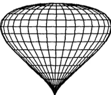
Fig. 4. Tapered superquadric ellipsoids.
Examples of tapering are shown in Fig. 4 where a su- perellipse is tapered using different tapering functions. The first object is obtained using the tapering function
71"
f ( z ) = z ~ and the second one is obtained using the tapering function
f(z)
= cos z .3. 1.2. Twisting.
A twist operation can be approximated as differential rotation, just as tapering is a differential scaling of the global basis vectors. We rotate one pair of global basis vectors as a function of height, without altering the third global basis vector. An example of twisting operation is the twisting of a deck of cards, by which each card is rotated somewhat more than the card beneath it. Twisting operation preserves the vol- ume of the original solid.To do a twisting operation along the z-axis, twisting angle 0 should be a function of the z-coordinate of the point to be deformed. Global twisting along the z-axis is given by the following equations:
o = f ~ z )
co
= c o s ( 0 )So
= sin(0)X = xCo- ySo
Y = xSo + yCo
Z = z .
The twist proceeds along the z-axis at a rate of f '(z) radians per unit length in the z direction.
Examples of twisting are shown in Fig. 5 where a superellipse is twisted using different twisting functions. The first object is obtained using the twisting function
7r
0 = z ~ and the second one is obtained using the twisting function 0 = sin z
3.1.3.
Bending.
Bending simulates an important manufacturing process for fabricating objects. An ex- ample of this operation is the bending of a bar stock or sheet metal.To make a bending along the y-axis, one has to specify a bent region along the y-axis. The range of the bending deformation is controlled by Ymin, and Ymax, with the bent region corresponding to values o f y such that Ym~n -< Y < Ymax. The axis of the bend is located
along[s, yo,~lr,wheresistheparameteroftheline.
The center of the bend occurs at y = Y0. The radius of
1
curvature of the bend is ~ . The bending angle 0 is constant outside the bent region, changes linearly in the central region. In the bent region, bending rate k, measured in radians per unit length, is constant. Out- side the bent region, the deformation consists of a rigid body rotation and translation. The length of the cen- terline passing through the object along the y-axis does not change during the bending process.
496 U(3UR Gt3DOKBAY and BOLENT (~ZG0(~
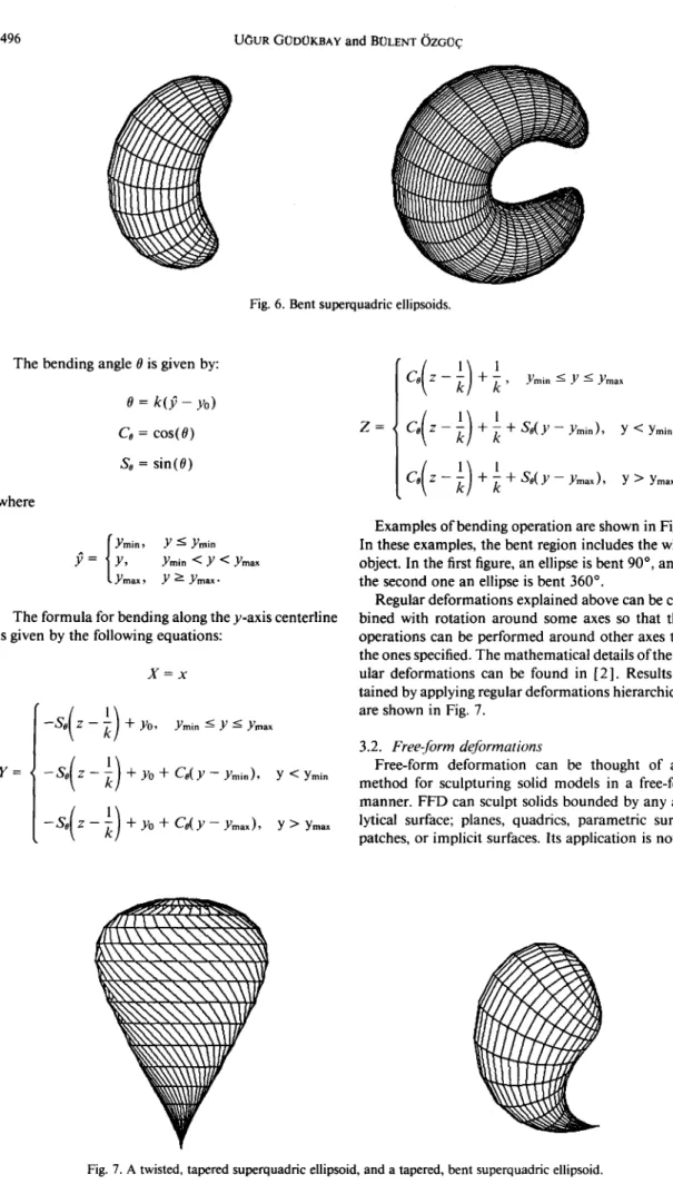
Fig. 6. Bent superquadric ellipsoids.
The bending angle 0 is given by: 0 = k ( ~ - Y0) Co = cos(0) $8 = sin(0) where f Ymin, Y -~< Ymin .v = ] Y , Ymin < Y < Ymax t Ymax, Y >--- Ymax-
The formula for bending along the y-axis centerline is given by the following equations:
X = x
Y =
- So( Z - k ) + Yo +
Co( Y - Ymin), Y < Yminy > Ymax Z =
Ymin --< Y < Ymax
Co(Z -k) q- k -r So(y--Ymin),
Y < YminY > Ymax.
Examples o f bending operation are shown in Fig. 6. In these examples, the bent region includes the whole object. In the first figure, an ellipse is bent 90 ° , and in the second one an ellipse is bent 360 ° .
Regular deformations explained above can be com- bined with rotation around some axes so that these operations can be performed around other axes than the ones specified. The mathematical details o f the reg- ular deformations can be found in [2]. Results ob- tained by applying regular deformations hierarchically are shown in Fig. 7.
3.2.
Free-form deformations
Free-form deformation can be thought of as a m e t h o d for sculpturing solid models in a free-form manner. F F D can sculpt solids bounded by any ana- lytical surface; planes, quadrics, parametric surface patches, or implicit surfaces. Its application is not re-
Free-form solid modeling 497 stricted to solid models, but it can also sculpt surfaces
or polygonal data.
In our system, two kinds of parametric surface patches, namely Brzier surfaces and superquadrics, are deformed in a free-form manner using FFD techniques. In fact, the objects are approximated using small poly- gons. Thus, the deformed data are actually polygonal data.
The free-form deformation is initiated by defining a three-dimensional grid of control points about the region to be deformed. The objects to be deformed are embedded in the grid of control points that can be interactively deformed as if it is made of a flexible ma- terial. The objects themselves can also be regarded as if they are made of a flexible material, so that when the whole grid is deformed, the objects inside them are also deformed respectively.
The deformation function for an FFD operation is defined by a trivariate tensor product Bernstein poly- nomial as specified in [10]. Since it is very time con- suming to evaluate a trivariate Bernstein polynomial for lots of polygon vertices that are to be transformed, it is wise to convert the Bernstein polynomial to stan- dard power polynomial basis, which can then be eval- uated using Horner's method.
Steps of deforming an object using FFD technique can be summarized as follows:
1. Move control points from their undisplaced, latticial positions to their new positions.
2. Convert the Bernstein polynomial whose coeffi- cients are the displaced control points to a standard power basis polynomial.
3. Calculate free-form deformation position of each point on the object by evaluating standard power basis polynomial found in step 2.
Our system uses the algorithms in [11] to deform ob- jects in a free-form manner. The mathematical details of FFD technique can be found in [10]. Examples of FFD technique are shown in Fig. 8.
3.3.
Combination of regular deformations and FFD
technique
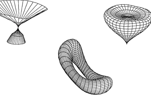
We have applied the two deformation techniques hierarchically to regular classes of objects by using our implementation. Results are shown in Fig. 9. The first object is obtained by tapering a superquadric hyper- boloid of one piece and applying an FFD to the tapered object. The second object is also obtained in the same way, but the initial object is an ellipse. The third object is obtained by applying an FFD to a superquadric to- roid to compress it and bending the compressed object.
4. THE USER INTERFACE
Since our system is interactive, we have to provide the user some facilities for defining parameters in cre- ating objects and for defining deformation parameters so that the user can use it in an efficient manner. The facilities provided by the system are explained in detail in the following sections.
4.1. Facilities.for creating B~zier surfaces" and super-
quadrics
In our system, the user can create the desired objects with the help of the object menu (Fig. 11). The user can either select Brzier surfaces or one of the super- quadrics to create a three-dimensional object.
To create Brzier surfaces, number of control points and number of curve points on each curve of the sur- face can be specified by the user, and control points for a Brzier surface can be interactively entered with the help of a mouse.
498 Ut3UR GtJDI~KBAY and BOLENT OZGf2ff
&
Fig. 9. Results of applying combination of regular deformations and FFDs.
To create superquadrics, scaling factors and expo- nents are interactively input from the user and the user is presented with a rough sketch, namely the bounding box, for the object that will be created, Then the user
may want the system to create the object specified by the parameters or discard it and specify different values for the parameters. The layout of the screen while pa- rameters of superquadrics are being specified is shown
1, 171 I
Control Potn¢e n1 : ~ n2 : 3 Curve Potnts ml : 15 m2 :
0 HSE_OFF 0 DEPTH_SORT
No. planes tn x d i r e c t | o n : 3 No. p l i n e e tn y d i r e c t i o n : 3
Epstlon I : 1.8 Epetlon 2 : 1.6
$callng f a c t o r tn z : [138] 8
Ftlename : dump RI: Help R2: Dtspley R3: Save
I
15 Resolution (1-368) : 36 I $HAOE_OFFI
No. pllne= tn z d i r e c t i o n : 3 Torus r a d t u s : 286.8 J 666R4: Copy prey, plane R5: O~ep, C n t r l . P t l .
. J . . , IN. x
Free-form solid modeling
L D l a p l a y mezler surface /
Dtaplay Superhyperbolold of one place I
Dlaplay Superhyporbolotd of t~o places
Dloplay $upartorotd
] hndlng along y-axls
~_.LTvlatlng around z-axis
r _ _ ~1 i1 I.,I i i l i i ii~, i i l l i l l ! ~ !;! I [$caltn9
Rotating around an a r b i t r a r y axis Froe-Forl DeforRatlona
I Translation
L E x l t frmm t h l s menu
Fig. 11. The object menu and the operations menu of the system.
in Fig. 10. The rectangular prism gives an idea to the user about the size of the object. Resolution of the superquadric objects can also be specified. In order to obtain very good polygonal approximations of super- quadric objects, a high resolution may be specified. However, using a high resolution will produce better results at the expense of slowing down the operations. 4.2.
Facilities for deforming objects
The implementation also provides facilities for de- forming the created objects. The operations that will be performed on the objects can be selected using the
499 operations menu (Fig. 11 ). Different twisting and ta- pering functions can be selected using menus. The user may select currently available twisting and tapering functions for these operations or select the option for specifying a new twisting or tapering function. If the user selects this option, a new window appears on the screen in which he or she can enter the function for twisting or tapering operation in infix notation using the keyboard. Also, bending region and center of bend can be specified interactively for bending operation.
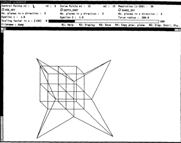
To do an FFD, the user is presented with a regular lattice of control points. The number of planes in
x,
y, and z directions can be specified interactively. In this way, the user may select between high quality and speed of the operations. If the number of control points in each direction is high, the deformation specified will be better, but operations will be slower. On the other hand, if the number of control points in each direction is low, operations will be faster, but deformations will not be high quality.The user may take each plane parallel to the xy- plane and change the coordinates of points interactively with the help of a mouse. He or she may see the lattice of control points any time during that process. After deforming lattice of control points, the user can get the deformed object according to the specified lattice. Fig. 12 shows a lattice of control points generated by our system.
Display facilities such as shading and hidden-surface elimination are also provided by the system so that
' - T ' l ~ n n l
C o n t r o l P o t n t s n ! : ~ n2 : 3 Curve P o t n t s m l : 15 m2 : 1S R e s o l u t i o n (1-36B) : 36
~-sHSF__OFF ~-~DEPTH_SORT ~SHAOE_OFF
No. p l a n e s t n x d i r e c t i o n : 3 No. p l a n e s t n y d i r e c t i o n : 3 No. p l a n e s t n z d i r e c t i o n : 3
E p s t l o n 1 : 1 . 8 E p o i l o n 2 : 1.8 Torua Padtus : 289.B
S c a l t n g ~ a c t o r t n z : [ 1 3 8 ] G ~ 688
Ftlonae~e : dump R I : H e l p R2: D i s p l a y R3: Save R4: Copy i ~ e v . p l a n e RS: D t s p . C n t r l . P t s . V ] '
:1
500 UGUR GODOKBAY and BOLENT OZGO~ they can be used to obtain realistic scenes. The imple-
m e n t a t i o n uses the facilities provided by Sun View t system such as windows, panels, a n d m e n u s [ 1 2 ] .
5. CONCLUSIONS
A system is developed to create the objects a n d scenes that the user desires through the use of a set o f primitive objects a n d a set of operations to deform these primitives. Two different deformation techniques are used in the i m p l e m e n t a t i o n o f the system. Since both deformation techniques have advantages a n d dis- advantages, we have c o m b i n e d them.
O u r system can be used to model objects with free- form surfaces or to sculpt objects. Both of the defor- mation techniques can be applied hierarchically a n d interchangeably through a set of user interface facilities provided by the implementation. By c o m b i n i n g the two approaches, some of the problems peculiar to each method disappear a n d the advantages of both ap- proaches are utilized.
REFERENCES
1. A. H. Barr, Superquadrics and angle-preserving transfor- mations. IEEE Computer Graphics and Applications
1( 1 ), 11-23 (January 1981 ).
t Sun View is a registered trademark of Sun Microsystems.
2. A. H. Barr, Global and local deformations of solid prim- itives. Computer Graphics 18 ( 3 ), 2 !,30 ( July 1984). 3. P. B~zier, Numerical ControlwMathematics and Appli-
cations John Wiley and Sons, London (1972). 4. M. S. Casale, Free-form solid modeling with trimmed
surface patches. IEEE Computer Graphics and Applica- tions 7( 1 ), 33-43 (January 1987).
5. H. Chiyokura, An extended rounding operation for mod- eling solids with free-form surfaces. IEEE Computer Graphics and Applications 4(7 ), 27-35 (July 1984 ). 6. R. T. Farouki and J. K. Hinds, A hierarchy of geometric
forms. 1EEE Computer Graphics and Applications 5(5 ), 51-78 (May 1985).
7. U. Giidiikbay and B. Ozgii¢, Deformation of solid models.
Proceedings of the Fourth International Symposium on Computer and Information Sciences, Ce~me, Turkey, 525-534 ( 1989, October).
8. B. W. Kemighan and D. M. Ritchie, The C Programming Language Prentice Hall, Inc., Englewood Cliffs, NJ (1978).
9. F. Kimura, Geomap--Ill. Designing solids with free-form surfaces. IEEE Computer Graphics and Applications 4(6), 58-72 (June 1984).
10. T. W. Sederberg and S. R. Parry, Free-form deformation of solid geometric models. ACM Computer Graphics (Proc. SIGGRAPH) 20(4), 151-160 (August 1986). 11. T.W. Sederberg and S. R. Parry, Free-form deformation
of polygonal data. In Proceedings of the International Electronic Image Week, Nice, France, 633-639 (April 1986).
12. Sun Microsystems, Sun View Programmer's Guide,