c
⃝ T¨UB˙ITAK
doi:10.3906/elk-1305-240 h t t p : / / j o u r n a l s . t u b i t a k . g o v . t r / e l e k t r i k /
Research Article
A new high-performance current-mode fuzzy membership function circuit and its
application
Turgay TEMEL∗
Architecture and Engineering, Mechatronics Engineering Department, Faculty of Natural Sciences, Bursa Technical University, Osmangazi, Bursa, Turkey
Received: 28.05.2013 • Accepted/Published Online: 01.10.2013 • Printed: 28.08.2015
Abstract: A new current-mode fuzzy-membership function circuit is proposed. The circuit has a very compact and simple architecture based on the simultaneous use of winner- and loser-take-all topologies. The circuit has also the advantage of easily adjusting generated membership function characteristics such as center or mean and width with a straightforward application of respective input currents. It is shown that the new circuit outperforms previous counterparts in terms of speed, power consumption, layout area, and robustness to variations in design parameters and errors. As an application, a fuzzy-classifier is designed with a new membership circuit as a seven fuzzy level controller. Key words: Fuzzy logic, decision-making, current-mode circuit design, winner-take-all circuit, loser-take-all circuit
1. Introduction
A membership function of a fuzzy set is a representative measure for an object of interest as a member [1]. In fuzzy logic it refers to the degree of truth in part between 0 and 1. Fuzzy logic truth takes into account the membership in vaguely defined sets. Although fuzzy membership is not based on likelihood, it is characterized by similar axioms as probabilistic interpretation, e.g., the sum of fuzzy memberships of an object to all respective fuzzy sets is 1. Fuzzy classifiers or controllers assume that an object is assigned to a linguistically defined fuzzy set on the basis of majority.
The design of an analogue membership function circuit (MFC) has drawn considerable attention for accurate, low-cost implementation of fuzzy controllers. Operational transconductance amplifiers (OTA) have been utilized in realizing compact MFCs [2,3]. In OTA-based MFC designs device nonlinearities and biasing conditions limit performance and input range. On the other hand, the current-mode approach provides high-speed, low-switching voltage capabilities for MFC implementations [4]. Most major current-mode MFC designs have resorted to piece-wise linear (PWL) membership functions owing to the immediate simplicity of current summation/subtraction at the nodes, which makes it possible to achieve switching for a desired linguistic fuzzy rule. For example, designs in [4–7] rely on a truncated (or bounded) difference operation with prespecified slopes in linearity. On the other hand, differential-stage based MFC designs in [8,9] take advantage of the cascaded behavior of differential stages toward a Gaussian-like membership function with programmability of mean and width. In the latter the programmability is attained through transistors that operate in the triode region at the output nodes, while in the former it is simply obtained through suitably biasing voltages across the output current.
However, they have the following common disadvantages: successive wired-arithmetic operations in the form of a current summation/subtraction reduce the maximum dynamic range of output, i.e. random design and process deviations and mismatches add up such that fuzzy sets will need larger intervals; the intense use of current-mirrors makes design discrepancies a serious issue; the choice of mirror type, e.g., the use of cascode mirrors, despite their better output response (i.e. small-signal output resistance), can limit the range of the input current given a supply voltage.
In this study a new current-mode fuzzy MFC is presented by combining both winner-take-all max (WTA-MAX) and loser-take-all min (LTA-MIN) topologies in simultaneous use. New MFC yields a Gaussian-like membership function with direct programmability of the resulting function. It is shown that the proposed design has much better design and performance characteristics compared with previous designs. As an application, a fuzzy controller/classifier with seven sets is designed with MFC.
2. Description of the proposed circuit
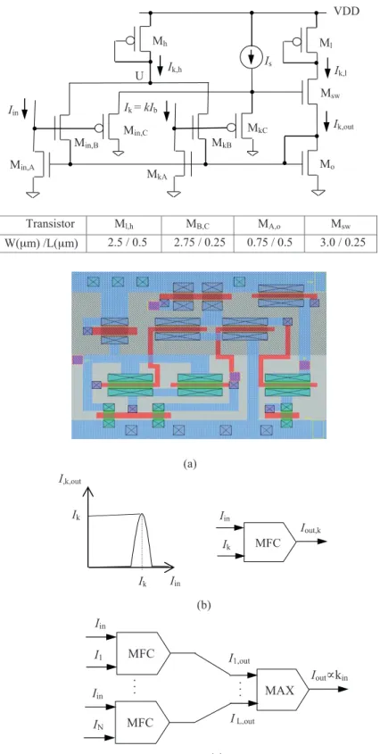
A new current-mode MFC shown in Figure 1a compares the input current Iin to the reference current of the
k-th fuzzy set or class, Ik= kIb, where Ib is a base current chosen fictitiously to represent the base fuzzy set,
i.e. level 1, or a regular interval between sets. In the circuit with current source Is, transistors MA, MC,
Msw, Mo, and Ml constitute a modified version of the LTA-MIN circuit given in [10], while transistors MA,
MB, Mo and Mh form the well-known WTA-MAX circuit [11]. Transistor MC in each cell is sized such that
it operates with a small saturation voltage for a given Is so that the output current Ik,out = Ik,l follows the
minimum of the inputs Iin and Ik as rapidly and closely as possible. It is seen that Ik,h = max( Ik, Iin) , and Ik,l = min( Ik, Iin) . The output current Ik,l flows only when Ik,h = Ik,l; hence Ik,out = Ik when Iin = Ik,
otherwise Ik,out = 0. Because membership lies between 0 and 1, a (normalized) membership of the input for the
k-th fuzzy set can be defined as min,k= Ik,out/ Ik, which could be reproduced by mirroring Ik,out by a factor
of 1/k. Due to device and design properties, Ik,out (min,k) will have nonlinear transition regions around Ik,
which can be considered as a fuzzification rule for the respective fuzzy set as shown in Figure 1b. These regions can be adjusted with MB,C and the value of Is such that neighboring min,ks intersect at a particular value
of min,k, e.g., 0.5. It should be noted that transistor Mh can be removed from the circuit and node U can be
directly tied up to a power supply (VDD) owing to the selective feature of the MAX circuit. The class label of the input, kin, is determined as kin = ⌈max(Ik,out)/Ib⌉ by MAXing all Ik,out (or min,k in case of normalized
outputs) terms in classification as shown in Figure 1c, where N is the number of fuzzy sets and ‘⌈ ⌉’ refers to the nearest greater integer. It should be noted that by suitably choosing Ik,hand Ik,l, the center and width
of the membership function can be adjusted, which can also be done by regenerating these currents through mirror circuits externally.
3. Application of the new circuit in a fuzzy controller and simulation results
The proposed MFC and its predecessors in [4–7] using the PWL method and the design in [9] based on cascaded differential stages were designed and simulated for a seven-set/level fuzzy controller/classifier with respective membership functions. Simulations were performed using TSMC 0.25 µ m HSPICE (level-49) parameters in full postlayout extraction with 1.8V supply voltage. In all designs body-biased effects were included and transistors were sized for optimum DC and transient characteristics with an input current range of 0 through 70 µ A. Bias voltages Vbn and Vpn in [4] were obtained by using adequate voltage reference circuits formed of
diode-(a) (b) Transistor Ml,h MB,C MA,o Msw W(μm) /L(μm) 2.5 / 0.5 2.75 / 0.25 0.75 / 0.5 3.0 / 0.25 Iin I,k,out Ik Ik MFC Iin Ik Iout,k Ml U Iin VDD Is Min,A Msw Mo Ik,l Ik = kIb Ik,h Min,C Mh Min,B MkA MkC MkB Ik,out (c) . . . . . . I1,out MAX I L,out Iout∝kin MFC Iin I1 MFC Iin IN
Figure 1. (a) Proposed MFC cell for the k-th fuzzy set, and its layout with TSMC 0.25 µ m technology for k = 1; (b) its expected DC transfer characteristics and block representation; (c) fuzzy-classifier block representation.
connected PMOS and NMOS transistors, respectively. The base current Ib in this study, the reference current Iref in [4–6], and the modal norm current Inorm used in [7] were taken at 10 µ A and raised to the respective set
reference levels for comparison by mirroring. Circuits in [4–7] were adjusted such that the linear membership functions of neighboring sets intersect at almost 0.5 with a transition slope of 1 at the rising and falling edges. For the design in [9], which employs cascaded differential stages, the bias current was chosen to be 10 µ A with PMOS transistors of an aspect ratio W( µ m)/L( µ m) = 0.75/0.25, while the input transistors of the input stages were fixed to a suitable aspect ratio of W( µ m)/L( µ m) = 0.75/0.25 such that the mean values have resorted to the respective fuzzy levels described above, which corresponds to the input voltage difference of 1.1 V. The programmability transistors, which operate in the triode region, have been connected to VDD with suitable aspect ratios for the desired fuzzy level. The output of each design was conditioned on a diode-connected NMOS transistor with a dimensional aspect ratio of W( µ m)/L( µ m) = 0.75/0.25. All inputs were chosen as sourcing and they were reproduced, if necessary, using appropriate mirror circuits.
For the new MFC the sourcing inputs were reproduced and directed to the input nodes by using p-type current mirrors with transistors of a dimensional aspect ratio of W( µ m)/L( µ m) = 1.5/0.25. Bias current Is
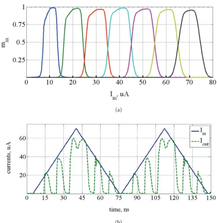
was taken at 1 µ A for all sets and it was reproduced by a diode-connected PMOS transistor with an aspect ratio of W( µ m)/L( µ m) = 0.5/1. Figure 2a illustrates a generic membership function min versus Iin with each
curve representing min,k centered at the respective reference current k Ib. As an application of the proposed
MFC, a single-input fuzzy classifier shown in Figure 1c for seven sets was also designed without normalizing the outputs of the MFC cells to visualize the label of the set the input belongs to. Figure 2b illustrates transient simulation results of the designed classifier at k = 2, 4, and 6, i.e. class reference currents were applied at only these levels while reference inputs of other sets were left open. The designed classifier occupied a layout area of 458 µ m2 with 91 transistors and had delays of 2.4, 2.0, and 1.8 ns for k = 2, k = 4, and k = 6, respectively,
while the average power drawn from VDD was found to be 6.1 mW for the input waveform shown in Figure 2b. The designed MFCs were also examined concerning their robustness and reliability against discrepancies due to random design parameter variations and noise effects generated in devices [12] for determining a respective dynamic range. The output current for the k-th fuzzy set then is given by Ik,out( Iin= Ik) = Ik+∆Ik, where the
first component Ik is the nominal component, while ∆Ik refers to random variations. HSPICE DC simulation
results indicated that the nominal component of the output current for the circuit given in Figure 1a satisfies linearity up to max( Iin) = 86 µ A for all k values. On the other hand, a reliable operation given a fuzzy set/level
characteristic of the design is determined by the second component of the output current. From a statistical point of view it is known that more than 90% of possible random occurrences, which obey a particular Gaussian distribution, reside within the range of 3 times the standard deviation around the nominal (mean) value. That is, for a safe operation within a chosen fuzzy set level, |∆Ik| < 3σ∆I,k< Ib / 2 [13]. For this objective, for each
design studied Iin was varied between 0 and 70 µ A, while Ik was kept at 20 µ A, 40 µ A, and 60 µ A for k =
2, 4, and 6, respectively. For each k a set of 100-iteration Monte Carlo DC simulation analysis using a normal Gaussian distribution that represents the relative variations in aspect ratios (W/L) with a standard deviation of σ∆W/W,∆L/L = 5% and variations in zero-body-bias threshold voltages (VTO) with a standard deviation of
σ∆V T O = 25mV was carried out. In each experiment of the analysis the quantity ∆ min,k = ( Ik,out – Ik) / Ik,
where Ik,out is the output current with supplied design parameters of variations computed. As a merit for
comparison, a DC dynamic range can be defined as DRk (dB) = 10log [ | max( Iin / Ik ) |2/( σ∆m,k)2], which
(a)
(b)
Figure 2. (a) Membership function DC characteristics of the proposed MFC for seven fuzzy sets; (b) transient simulation results of the designed classifier with proposed MFC for k = 2, 4, and 6.
the MFCs examined: number of transistors (NTR), layout area, dynamic range (DRk) , as well as the average
power drawn from VDD (PV DD) and delay τk for the input waveform in Figure 2b.
Table. Design characteristics of the proposed (New) and previous MFCs and their performance measures for input waveform in Figure 2b.
Design NTR Layoutarea (µm)2 DRk = 2k(dB) – τk = 4k (ns) k = 6 PV DD (mW)
New 10 91.8 58 – 1.5 56 – 1.2 56 – 1.0 1.6 [4] 16 132.4 54 – 2.1 53 – 1.9 53 – 1.5 2.9 [5] 26 229.6 50 – 2.3 46 – 2.0 47 – 1.9 3.5 [6] 32 269.5 48 – 2.7 44 – 2.4 43 – 2.1 4.2 [7] 28 256.9 51 – 2.7 48 – 2.3 45 – 2.1 4.0 [9] 18 294.6 47 – 3.2 42 – 2.6 41 – 2.4 2.7 4. Conclusions
A new simple-architecture, high-performance current-mode membership-function circuit is described. The new circuit has the architectural advantage that the generated function can be modified in shape externally. It is shown that the new circuit exhibits much better performance characteristics in terms of speed, power consumption, layout area, and robustness to parametric variations than previous designs. These characteristics are expected to make the new MFC a reliable unit for neuro-computational and decision-making applications.
Acknowledgment
This work was supported by the Scientific and Technological Research Council of Turkey (T ¨UB˙ITAK) under Project no: 107E059.
References
[1] Zadeh, LA. Fuzzy sets. Elsevier Information and Control 1965; 8: 338–353.
[2] Azeem MF, Baig A. Design and fabrication of basic building blocks for analog implementation of programmable fuzzy logic controller. In: IEEE Information Reuse and Integration Conference; 13–15 August 2007; Las Vegas, NV, USA: IEEE. pp. 563–569.
[3] Wilamowski BM, Jaeger RC, Kaynak MO. Neuro-fuzzy architecture for CMOS implementation. IEEE Trans Ind Elect 1999; 46: 1132–1136.
[4] Baturone I, Solano SS, Huertas, JL. Current-mode singleton fuzzy controller. In: IEEE Fuzzy Logic, Neural Networks and Soft Computing Conference; 26–29 June 1994; Orlando, FL, USA; IEEE. pp. 647–648.
[5] Mesgarzadeh B. A CMOS implementation of current-mode min-max circuits and a sample fuzzy application. In: IEEE Fuzzy Systems Conference; 18–20 June; 2004; IEEE. pp. 941–946.
[6] Amirkhanzadeh R, Khoei A, Hadidi K. A mixed-signal current-mode fuzzy logic controller. Elsevier Int J Elec and Comm 2005; 59: 177–184.
[7] Kashtiban MM-, Khoei A, Hadidi K. A current-mode, first-order Takagi-Sugeno-Kang fuzzy logic controller, sup-porting rational-powered membership functions. IEICE Trans Elec 2007; E90-C(6): 1258–1266.
[8] Baradaranrezaeii A, Zarei M, Khalilzadegan A, Khoei A, Hadidi K. A CMOS referenceless membership function generator. In: Iranian Electrical Eng Conference; 17–19 May 2011; pp.1–6.
[9] Khaneshan TM, Nematzadeh M, Khoei A, Hadidi K. An analog reconfigurable Gaussian-shaped membership function generator using current-mode techniques. In: Iranian Electrical Eng Conference; 15–17 May 2012; pp. 145–149.
[10] Temel T. High-performance current-mode multi-input loser-take-all minimum circuit. IET Elec Lett 2008; 44: 718– 719.
[11] Lazzaro J, Ryckebusch R, Mahowald A, Mead C. Winner-take-all networks of O(n) complexity. In Touretzky D, editors. Advances in neural information processing systems I: San Mateo, CA, USA: Morgan Kaufmann, 1989. pp. 703–711.
[12] Gotarredona TS, Barranco BL. A new five-parameter MOS transistors mismatch model. IEEE Electron Devices Lett 2000; 21: 37–39.
[13] Temel T, Morg¨ul A. Implementation of multi-valued logic gates using full current-mode CMOS circuits. Kluwer Analog Integr. Circuits and Signal Process 2004; 39: 191–204.