10.11 09IUL TSYM.20 14.0640
Designing Efficient CMUT Cells for Airborne
Applications
Asli Unlugedik a,b, A. Sinan Tasdelen b, Abdullah Atalar band Hayrettin Koymen b aDept. of Electrical Engineering, Stanford University, Stanford, CA 94305-9505, bDept. of Electrical and Electronics Engineering, Bilkent University, Ankara, Turkey 06800
Email: [email protected]
Abstract-In this work, we study airborne CMUT cells with vacuum gap where silicon plate is operated both in elastically linear and nonlinear regimes. We report the results of a new mode of operation where the plate center swings the entire gap. The plate is kept in elastically linear region in this mode. Very large pressure levels are obtained at relatively low drive voltage levels. The operation is very efficient but the bandwidth is less than 1 %. We considered operating the silicon membrane in elastically nonlinear region for larger bandwidth without sacrificing efficiency. This is achieved by employing the stiffening effect due to the atmospheric pressure. We derived the new model of the CMUT, where the membrane profile deviates from linear profile as a function of the differential static pressure on it. We present the force, the compliance models and the static analysis of stiffened CMUT cells in this work.
Keywords-airborne CMUT; nonlinearity
I. INTRODUCTION
A cross sectional view of a circular airborne CMUT is shown in Fig. 1, where a is the diameter of the CMUT, tge is the effective gap height, ti is the insulating layer thickness, tm
is the membrane thickness, and
F
is the total force exerted on the membrane. Acoustic wave is generated by applying an electrical signal between the electrodes of CMUT.The mass of the plate must be kept at a minimum for a given operating frequency to achieve a wide bandwidth [1], since the radiation resistance of air is very low. However, CMUTs with thin radiating plates experience increased atmospheric pressure and therefore a larger static plate deflection. This causes nonlinearity in compliance and the plate becomes stiffer. This effect causes an increase in the resonance frequency of the CMUT. The resonance frequency is also affected by the nonlinearity in the transduction force, which has an opposite effect.
In the first part of this work, we propose a mode of operation where these two effects are counter balanced to provide a very large swing amplitude at resonance, while the deflection-to-membrane-thickness ratio is kept below 0.2. In this minimum voltage mode (MVM) , the membrane center swings the entire gap at the lowest possible drive level in unbiased operation. In unbiased operation CMUT is driven with sinusoidal signal with zero bias voltage
v =V cOS
(
!!!..t+8I
'" m 2)
(1) 978-1-4799-7049-0/14/$31.00 ©20 14 IEEE 2564 Fr
.. ...
}
r
Top £Iec(rode�"--- BOIIOlI' Electrode aFig. I. Cross sectional view of circular airborne CMUT.
An accurate circuit model-based characterization, given in [2], is used to make performance analysis [3]. The performances of the fabricated CMUTs are tested and compared with the circuit model results.
Airborne CMUTs are typically analyzed and designed to operate in elastically linear region. The linear regime constraint defines a limit on the achievable lowest quality factor and therefore on the widest achievable bandwidth. The limitation of the quality factor can only be overcome by using lighter and/or stiffer materials [4] as the membrane material.
In the second part of this paper, we present an approach to overcome this limitation and analyze airborne CMUTs in nonlinear regime to obtain a wider operation frequency band. It is shown that a wide bandwidth can be achieved by using silicon as a stiffened plate material. We present the transduction force, the compliance and the static analysis of CMUT cells with stiffened plates in nonlinear operation.
II. LINEAR REGION
The mechanical quality factor, Q,m of a single CMUT cell operating in the linear region [1], is given by
Q m = m,LR'"
+
XRR(k,a) =��&+
X,(k,a)RRR (k,a) R, (k,a) a Po R, (k,a) (2)
where kr is the wave number in air at the resonance frequency
Rl and Xl are the normalized radiation resistance and reactance of the CMUT cell and Pm/PO is the ratio of the density of plate material to that of air. Unfortunately, Pm/PO is very high for typical micromachining materials. The only means of having a lower quality factor in lossless CMUT is to have a very small tm/a ratio. However, in a CMUT with vacuum gap, atmospheric ambient pressure deflects thinner plates, causing increased plate stiffness due to nonlinear effects [4]. Operation of a CMUT cell with a thin plate under
uniform pressure can be described using a linear mechanical model, if the center deflection
(Xp)
is less than one fifth of the plate thickness(tm) [4].
The maximum displacement of the plate center is limited to gap height, which can be taken as
tge,
approximately.(3)
and the relation between
tlrla,
andk,a
can be obtained at the unstiffened mechanical resonance frequency as(4)
Fig.
2
and3
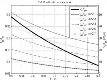
can be used to design a CMUT cell with desired properties.Fpt/Fpg(<l)
basically defines the fractional deflection of the plate under ambient pressure. With no applied bias voltage, it is equal toXp/tge-
Since the maximum deflection can betgn
for operation in linear regime,tg/tm
must be less than0.2.
Since a smallk,a
is desirable, it is best to chooseFpt/Fpg
as large as possible. Having chosen theFpt/Fpg
andk,a
values,tg/tm
andV/tge
can be determined from Fig.2. Then, Fig.3
can be used to find the values ofQm
anda/tm.
Nearly optimal and practical values are obtained, when we choose
Fpt/Fpg=O.S, k,a=2.1
and use Fig.2 to gettg/tm=0.194
andV/tge=14.6
V/Jlm. Fig.3
givesQm=147
andaltm=33.3.
Harmonic balance simulations show that a maximum swing(1- Fpt/Fpg) tge=0.2tge
is obtained with an unbiased sinusoidal drive signal at a frequency of0.497fr
with aO.ISSVc
peak amplitude.For example, at
f,-=100
kHz(kr=IS4S),
we finda=1.14
mm. Hencetm=34.2
Jlm,tge=6.64
Jlm andVc=96.7
V. We find the maximum peak swing amplitude(1-Fpt/Fpg)tge=1.32
Jlm. This swing amplitude is reached using an unbiased sinusoidal input signal at49.7
kHz, withIS.2
V peak value.CMUT wilh silicon plale in air
50
... Ig/Im. ka=2.2 0.25 . -- - -Ig/Im· . -. -Ig/Im. ka=2.3 40
ka=2.5 _Ig/Im. ka=2.7 0.15 L-__ -L __ � ____ � __ � ____ L-__ _L ____ L_ __ �O 0.55 F Pb/F Pg 0.75 0.8 0.85 0.9
Fig. 2. Design graph for a CMUT with silicon plate operating in air. V, is the collapse voltage under ambient pressure.
CMUT wilh silicon plale in air
�0 .---.---�----�---.----�--�--�.---�34 " "-
�
190 .. .. >""i....
�
__ Qmm .. 180 Cl170 160 150 : "- " ,: "-: :,
. . - --. . . . .. .•. . . . , . .. . . • . . , : "'-: , , , : 1402.1 L---�--�.---�--�.-.-L---�--2.2 ��--�2.9 22Fig. 3. Design graph for a CMUT with silicon plate operating in air.
It is analytically proven that possible lowest quality factor in mechanically linear region for a lossless silicon plate is
140
[3].
The quality factor can be decreased by introducing loss mechanism which decreases the efficiency. Operating the CMUT in elastically nonlinear region provides larger bandwidth without sacrificing efficiency.III. CMUT WITH STIFFENED PLA TE
The only way to achieve low loss and low quality factor simultaneously is to increase radius to plate thickness ratio,
altn" [1].
Asa/tm
is increased the plate becomes more compliant. The center deflection-to-thickness ratio may exceed0.2
due to the atmospheric pressure. The stiffness of the plate increases and the resonance frequency shifts upwards. As a result, a relatively thin plate may act like a high stiffness material when it is deflected beyond its linear operation limits.A. Profile
of
Stiffened PlateThe displacement profile assumed in
[2]
is not applicable for stiffened plate. A very good approximation to stiffened profile is obtained using the following profile(5)
where
Xp
is the center deflection and1
r",l
1 +0.293S
(
W)2
-1.l23xlO-3
(
wt
+ 2.657xlO-6
(W)6
(6)
Here,
w= Xp/tm
is the deflection to membrane thickness ratio. The average and rms displacements for the profile in(5)
differ from
[2]
and are as follows:The average displacement,
XA,
is defined aswhere with I
(1
2 )2
X
Av = 2
I
-
P2
pdp
=
A(w)
Xp
0(l-rp )
A(W)
_
1
1
- 3 0.6700S+1IvA '
VA = 0.00094(w)4 -O.0372S(wf +0.68772(w)2
+3.030762
and the rms displacement, XR, is defined as
where
B(w)'" 1
1
.J5
0.7821OS
+
11 vIJ '
VB= 0.0043(w)4 -0.0406S(W)3 + 1.04479 (W)2
+4.S89366
B.
Induced stress (7)(8)
(9)
(10) (11 ) (12)The induced stress at the rim of a thin silicon membrane is studied by finite-element-analysis (PEA)
[1], where it is found
to be proportional to the square of tm
/a ratio and its dependence on Xp/tm is also reported. The induced maximum stress, Tim, can be accurately modeled aswhere Yo is the Young's modulus and (J is the Poisson ratio of
silicon. Hence, for an allowable maximum induced stress,
Tm(lX' we must have
(14)
For example, if a safe maximum allowable stress in silicon is Tim=SOO MPa, then
(1S) for large
w.
Therefore, to allow a plate center deflection of twice its thickness(w=2),
the radius must be larger than1.26 mm for a
IS
flm thick silicon membrane.C. Energy
The potential energy in the membrane is calculated as
where Epm is potential energy due to static pressure.
(17) where
u= Xp/tge,
is the deflection normalized to effective gap height, and.
Xp
�r
+4(I-r)u
g,(r,u)
=_1
{[ r
+2(I-r)u
1
tge (18)arctanh[�r
+4(I-r)U
]
+lln
(
l-r
)}
(2-r)
2 l-u
D. Transduction ForceTransduction force is obtained by evaluating the gradient of the energy along XR:
where f 11
=
d(
Epe) =
X
1
d fP
dXRB(w)+-P -B(w)
tm dw E. Compliance (19)Nonlinear dependence of the compliance on the deflection of the plate is studied in [l], where an FEA-based method to quantify this dependence is also given. A very good approximation to this variation can be expressed as:
CR
1
--
'"---
--::-----
----::-Clim1+0.61712(w)2 -0.00698(w)3
where, CRm, rms compliance in linear equivalent circuit model is given in
[2].
F. Static Ambient pressure
For the displacement profile given by
(2)
the rms static ambient pressure differs from[2]
and it is defined asA((w)
2 F"R =-(
-)
JraFa
(22)Bf
W whered
Af (w)
=A( w)+ w-A( w)
(23)dw
andd
Bf (w)
=B( w)+ w-B( w)
(24)dw
IV. STATTCANALYSISThe static force equilibrium between transduction force, force due to ambient pressure and restoring force is given as
(25) This equilibrium can be expressed as
3
5B( (w)B
(w)
pc(t�e/tm)u
-3AJ (w)
;
R (26)as in [2], where
Vr
is the collapse voltage for an unstiffened CMUT in vacuum and F� is the force required to deflect the membrane center bytge'
CMUT biasing chart (CBC) [2] for stiffened membrane is depicted in Fig.
4
using (23)
. The collapse voltage for a given normalized deflection and static bias increases as the membrane is stiffened. The depression due to static pressure is no longer equal to Fi/Fg as in unstiffened CMUT [2], but it is a function oftg/tm
and F i/F�. The collapse line is also shown in the Fig4.
The collapse voltage of the CMUT also increases as the membrane is stiffened. The collapse voltage of stiffened membrane in vacuum is a function of
tg/t'm Vrs(tg/tm).
The collapse lines for differenttg/tm
values andVrsCtg/tm)
are depicted in Fig.5.
Fig.4. CBC of CMUT with stiffened membrane for tg,ltm=5.
5
.---�---�---._----_,---_.----__.4.5
4"
3.5
3
<:��2.5
> " " " --Unstiffened -,-,.t It ge m=1
___ t It =2 ge m ... -,-,.t It =3 ge m "'" " "t It ge m=4
-,-"t It ge m=5
---t It=10
2
ge m """-V rs1.5
0.5
�.4
XpltgeFig.5. V"(t,,Itm) and collapse lines for CMUTs with t,,Itm varying from unstiffened to 10.
ACKNOWLEDGEMENT
This work is supported in part by Turkish Scientific and Research Council (TUBITAK) under project grants llOE216. AA thanks TUBA for the research support.
REFERENCES
[1] A Unlugedik, A. Atalar, and H. Koymen, "Designing an efficient wide bandwidth single cell CMUT for airborne applications using nonlinear effects," in Proc. lEEE Ultrasonics Symp., 2013, pp.1416-1419. [2] H. Koymen, et a!., "An improved lumped element nonlinear circuit
model for a circular CMUT cell," IEEE Trans. on Ultrason., Ferroelec. and Freq. Cont., vol. 59, no. 8, pp. 1791-1799, August 2012.
[3] AUnlugedik, et al., "Designing transmitting CMUT cells for airborne applications," IEEE Trans. on Ultrason., Ferroelec. and Freq. Cont., accepted.
[4] AM. Cetin, and B. Bayram, "Diamond-based capacitive micromachined ultrasonic transducers in immersion,"IEEE Trans. Ultrason. Ferroelect. Freq. Contf., vol. 60, pp.414-420, 2013.
[5] E. Ventsel and T. Krauthammer, Thin plates and shells, 1st ed., New York: Marcel Dekker Inc., 2001.
[6] M. Kupnik, 1. O. Wygant, and Butrus T. Khuri-Yakub, "Finite element
analysis of stress stiffening effects in CMUTs, " in Proc. lEEE
Ultrasonics Symp., 2008, pp. 487-490.