13th International Conference on Mathematical Methods in Electromagnetic Theory September 6 – 8, 2010, Kyiv, Ukraine
EFFECT OF THE OFF-FOCUS SHIFT OF THE FEED ON THE RADIATION
CHARACTERISTICS OF A 2-D PARABOLIC REFLECTOR ANTENNA
Taner O÷uzer 1, and Ayhan Altintas 3, Alexander Nosich 2
1 Electrical and Electronics Eng. Dept., Dokuz Eylul University, Buca, 35160 Izmir, Turkey 2 Dept. Electrical and Electronics Eng., Bilkent University, 06800 Ankara, Turkey
3 Institute of Radio-Physics and Electronics NASU, Kharkiv 61085, Ukraine
e-mail: [email protected]
Abstract – The parabolic reflector antennas are widely used in the telecommunication systems and generally have large aperture sizes like 50Ȝ to 80Ȝ and larger. Their reliable full-wave analysis with the conventional Method of Moments (MoM) or with the other numerical methods is difficult because of inaccessible speed and accuracy. This statement is valid both for 3D and 2D reflector antennas in both polarizations. The Method of Analytical Regularization (MAR) constitutes an alternative solution compared to the ordinary MoM, which can provide only 1-2 digit accuracy. It provides finer accuracy within a reasonable computation time because the computational error can be decreased simply by increasing the matrix size in MAR. We have previously developed this method for the accurate simulation of the arbitrary conical section profile 2D reflector antennas, and the corresponding codes have provided us with accurate benchmark data. Here we study a similar problem however with the feed simulated by Complex Source Point (CSP) source located at an off-focus point on the symmetry axis of a front-fed reflector antenna. The numerical results are presented for the radiation characteristics including the forward and backward directivities and the radiation patterns in all directions.
I. INTRODUCTION
Reflector antennas are generally large-electric-size 3D structures. Their 2D counterparts are also important from the computational electromagnetics point of view. Commonly larger reflector antenna systems can be simulated by high-frequency methods based on the ray-tracing optical techniques including geometrical and physical optics (GO and PO), geometrical and uniform theory of diffraction (GTD and UTD), gaussian-beam methods, etc. These techniques are not based on exact electromagnetic formulation of the scattering problems; still they are useful approximations valid in specific regions of space and far from reflectors.
On the other hand, purely numerical techniques are not efficient for large-size reflectors because of the speed and accuracy limitations. We imply that the code using ordinary MoM [1] is quite slow and accurate only within 1-2 digits, for example for an 80Ȝ reflector that is not enough for practical simulations. There exist some special studies published in the literature. For example, in [2] the authors used the entire-domain basis functions in MoM algorithm to produces reasonably accurate results; still the code worked with a CRAY supercomputer. This way of solution, however, can not be adapted easily to various practical geometries compared to the MoM using the subdomain basis functions. Furthermore, the Fast Multi Pole (FMP) based MoM, or its multi level version [3], and even their parallelizations have been proposed and tested. All these techniques now enable one to simulate a large reflector antenna within the reasonable computation time and with high enough accuracy. However these hardware and software facilities are available only in the limited number of centers in the world.
An alternative is the MAR method also known as semi-inversion [4]. Here some part of the kernel of the original operator (generally its strongest singular part) is extracted and then inverted analytically. In the analytical inversion, either the Riemann Hilbert Problem technique [4] or projection to the Chebyshev polynomials [5] can be exploited. Then we end up with an algebraic matrix equation which is of the Fredholm second kind so that the Fredholm theorems state that the solution exists and unique. Also when increasing the matrix size the results converge to the exact solution of the original electromagnetic boundary value problem.
We have used this MAR method in the accurate 2-D simulation of the arbitrary conic section profile reflector antennas with perfectly electrically conducting (PEC) surface [6,7], for both polarizations. Various numerical results have been obtained for the evaluation of the radiation characteristics assuming that the CSP feed was placed exactly at the geometrical focus of reflector.
Here the same conical section profile reflector antenna simulation is performed with the feed is located not in the geometrical focus of the parabolic reflector although still at the line of symmetry. The variations of the forward and backward directivites and radiation patterns are studied as a function of the feed position. Note that similar study had been undertaken in [8]; however, the authors used the methods having only limited accuracy.
13th International Conference on Mathematical Methods in Electromagnetic Theory September 6 – 8, 2010, Kyiv, Ukraine
Unlike them, with MAR we have a possibility to obtain 6-digit accuracy in the far zone for any feed locations including those shifted from focus.
II.DESCRIPTION OF THE METHOD
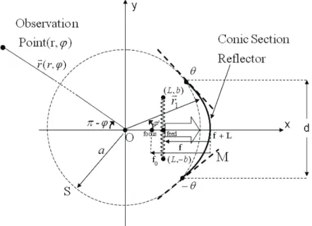
The problem geometry is associated with a zero-thickness curved PEC screen symmetrically illuminated by a directive feed (Fig. 1). The 2-D contour of the reflector’s cross section M can be elliptic, parabolic or hyperbolic arc, i.e. an arbitrary conical-section profile. Here we will take it as parabolic.
Figure 1: Geometry of the problem for the off-focus CSP feed.
The feed is assumed a CSP source; certain restrictions on its locations will appear due to the singularities of the corresponding field function. The central point of the feed aperture (shown by a wiggled line) is not necessarily at the geometrical focus of the reflector but still on the x-axis. When building the solution, the open arc of reflector contour M is completed to the closed contour C with a circular arc S of a certain radius a.
The rigorous formulation of the considered boundary value problem can be stated in terms of the Helmholtz equation of M, the Sommerfeld radiation condition far from the reflector and source, PEC boundary condition on
M, and an edge condition such that the field energy is limited in any finite domain around reflector edge. These
conditions guarantee the uniqueness of the problem solution.
The integral equations are obtained by using the theory of potentials and imposing the PEC boundary conditions on M for either of polarizations. Then according to the procedure given in [4,5,6], all functions are expanded into the Fourier series on C. The part associated with a circular closed contour of radius a is added and subtracted from the original contour kernel, and this part is treated with MAR-RHP technique. Inside the remaining integral, a regular function appears and double Fourier-series coefficients of this regular function are obtained effectively by Fast Fourier Transform technique. This is the semi inversion method for the non circular geometry. Then finally we obtain a regularized, i.e. a Fredholm second kind, algebraic matrix equation and previously mentioned properties are valid. Therefore the obtained numerical results can be thought as the benchmark data in terms of the accuracy, and other approximate methods should be compared to these data. The details of the method can be found in [4,6,7].
13th International Conference on Mathematical Methods in Electromagnetic Theory September 6 – 8, 2010, Kyiv, Ukraine
III.NUMERICAL RESULTS
Following the formulation and regularization performed according to the procedure given above, we have computed the radiation characteristics for a defocused CSP feed. As shown in Fig. 1, the feed position is f , the geometrical focus is f0 , and d is the reflector size. Various numerical results have been obtained for the far-field radiation including directivities and radiation patterns. In Fig. 2, the forward and backward directivities are plotted for the E-polarization case for f0/d 0.4and f0/d 0.6 cases, and parts (a) and (b) correspond to two reflectors with d 15O and d 30O, respectively. The /f d value (it relates to the reflector surface peak curvature) does not make any visible effect on the forward directivity. However in the backward directivity the larger /f d (that is the smaller curvature) increases value apparently because the edge points are located at a slightly larger distance for larger
b D / f d b D
under the fixed value of d. In Fig. 2(b), the aperture size is twice larger than in Fig. 2(a), and therefore the forward directivity increases appreciably. However the doubled aperture size reduces slightly the backward directivity because again the distance to the diffraction points, i.e. the edges, increases slightly. In the H-polarization, the forward and backward directivities are slightly higher than in the E-case due to the higher edge effects. If the logarithmic scale is used, as in Fig. 2, these small differences cannot be seen and therefore we do not show the curves for the H-polarization case.
Figure 2: Variations of the forward and backward directivities with respect to the feed position. Solid line is for and dashed line is for
0/ 0.
f d 6 f0/d 0.4, and parts (a) and (b) are for d 15Oand d 30Ocases, respectively. CSP aperture size is kb = 3 (see [6,7]) and the matrix size is Ntr = 350.
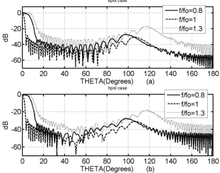
Finally the radiation patterns have been computed for three different feed positions including one that is the geometrical focus. The plots in Figs. 3(a) and 3(b) present the E and H-polarization cases, respectively.
13th International Conference on Mathematical Methods in Electromagnetic Theory September 6 – 8, 2010, Kyiv, Ukraine
Fig. 4: Normalized radiation patterns for the E and H polarization cases for various feed positions. The problem parameters are f0 12Oand d 30O, kb = 3 and Ntr = 350.
If the feed is at the true geometrical focus, the main beam is narrower and the side lobes in the penumbra region are lower, while if that is the feed shifted towards the reflector the main beam becomes wider and the backward sidelobes are almost at the same level as with the in-focus feed. In the opposite case of the is feed shifted away from the true focus. Then the main beam is even wider and all pattern level (both in penumbra and backward sectors) gets considerably higher compared to the previous two cases.
0 / 0. f f 8 3 0 / 1. f f VI.CONCLUSIONS
The effect of the axial shift of the feed from the geometrical focus on the radiation characteristics of a parabolic reflector have been investigated by the mathematically accurate MAR technique. The results quantify the conclusion of the aperture-integration theory that the feed should be shifted towards the parabolic reflector.
REFERENCES
[1.] A. F. Peterson, S. L. Ray and R. Mittra, Computational Methods for Electromagnetics, IEEE Press, 1998.
[2.] M. R. Barclay and W. V. T. Rusch, "Moment-method analysis of large, axially symmetric reflector antennas using entire-domain functions," IEEE Trans. Antennas Propagat., vol. 39, pp. 491- 496, 1991.
[3.] J. M. Song, C. C. Lu and W. C. Chew, "Multilevel fast multipole algorithm for electromagnetic scattering by large complex objects," IEEE Trans. Antennas Propagat., vol. 45, pp. 1488-1493, 1997.
[4.] A. I. Nosich, "Green’s function-dual series approach in wave scattering from combined resonant scatterers," in M. Hashimoto, M. Idemen and O. A. Tretyakov, Eds., Analytical and Numerical Methods in Electromagnetic Wave
Theory, Tokyo: Science House, pp. 419-469, 1993.
[5.] R. W. Scharstein, M. L. Waller, and T. H. Shumpert, "Near-field and plane-wave electromagnetic coupling into a slotted circular cylinder: hard or TE polarization," IEEE Trans. Electromagn. Compat., vol. 48, no 4, pp. 714-724, 2006.
[6.] T. O÷uzer, A. I. Nosich and A. Altintas, "E-polarized beam scattering by an open cylindrical PEC strip having arbitrary conical-section profile," Microwave Opt. Technol. Lett., vol. 31, pp. 480-484, 2001.
[7.] T. O÷uzer, A. I. Nosich and A. Altintas, "Analysis of arbitrary conic section profile cylindrical reflector antenna, H-polarization case," IEEE Trans. Antennas Propagat., vol. 52, pp. 3156-3162, 2004.
[8.] M. S. Narasimhan and K. R. Govind, "Front-to-back ratio of paraboloidal reflectors," IEEE Trans. Antennas Propagat., vol. 39, no.7, pp. 877-882, 1991.