İZMİR KÂTİP ÇELEBİ UNIVERSITY GRADUATE SCHOOL OF NATURAL AND APPLIED SCIENCES
M.Sc. THESIS
JUNE 2017
DEVELOPMENT OF VIBRATION PERFORMANCES OF HYBRID LAMINATED COMPOSITE MATERIALS BY USING STOCHASTIC
METHODS
Thesis Advisor: Assist. Prof. Dr. Levent AYDIN Melih SAVRAN
İZMİR KÂTİP ÇELEBİ UNIVERSITY GRADUATE SCHOOL OF NATURAL AND APPLIED SCIENCES
M.Sc. THESIS
JUNE 2017
DEVELOPMENT OF VIBRATION PERFORMANCES OF HYBRID LAMINATED COMPOSITE MATERIALS BY USING STOCHASTIC
METHODS
Thesis Advisor: Assist. Prof. Dr. Levent AYDIN Melih SAVRAN
(Y130105015)
HAZİRAN 2017
İZMİR KÂTİP ÇELEBİ ÜNİVERSİTESİ FEN BİLİMLERİ ENSTİTÜSÜ
TABAKALI HİBRİT KOMPOZİT MALZEMELERİN TİTREŞİM PERFORMANSLARININ STOKASTİK OPTİMİZASYON YÖNTEMLERİ
KULLANILARAK GELİŞTİRİLMESİ
YÜKSEK LİSANS TEZİ Melih SAVRAN
(Y130105015)
Makina Mühendisliği Anabilim Dalı
iii
Thesis Advisor : Assist. Prof. Dr. Levent AYDIN İzmir Katip Çelebi University
Jury Members : Prof. Dr. M. Evren TOYGAR Dokuz Eylül University
Prof. Dr. Buket OKUTAN BABA İzmir Katip Çelebi University
Melih SAVRAN, a M.Sc. student of İzmir Katip Çelebi University student ID Y130105015, successfully defended the thesis entitled “Development of vibration performance of hybrid laminated composite material by using stochastic methods”, which he prepared after fulfilling the requirements specified in the associated legislations, before the jury whose signatures are below.
Date of Submission : 03.07.2017 Date of Defense : 05.06.2017
iv
ACKNOWLEDGMENTS
I would like to express my sincere gratitude to my supervisor Assist. Prof. Dr. Levent Aydın for his advises, guidance, support, encouragement, and inspiration through the thesis. His patience and kindness are greatly appreciated. I have been fortunate to have Dr. Aydın as my advisor and I consider it an honor working with him.
I am also grateful to my friends for their support, encouragement and contributions.
Lastly, I would like to thank my family who have supported and encouraged me during my graduate studies.
June 2017 Melih Savran
v
TABLE OF CONTENTS
ACKNOWLEDGEMENTS ... IV TABLE OF CONTENTS ... V LIST OF TABLES ... VII LIST OF FIGURES ... X ABSTRACT ... XI ÖZET ... XIII CHAPTER 1. INTRODUCTION ... 1 1.1. Literature Survey ... 1 1.2. Objectives ... 5
CHAPTER 2. COMPOSITE MATERIALS ... 6
2.1. Introduction ... 6
2.2. Classification of Composites ... 8
2.3. Applications of Composite Materials ... 13
CHAPTER 3. MECHANICS OF COMPOSITE MATERIALS ... 17
3.1. Classical Lamination Theory ... 17
3.2. Vibration Theory of Laminated Composite Plates ... 22
CHAPTER 4. OPTIMIZATION ... 25
5.1 Single-Objective Optimization ... 26
5.2 Multi-Objective Optimization ... 26
5.3. Stochastic Optimization Algorithms ... 27
5.3.1. Diferential Evolution Algorithm (DE) ... 27
5.3.2. Nelder Mead Algorithm (NM) ... 28
5.3.3. Random Search Algorithm (RS) ... 30
vi
CHAPTER 5. STOCHASTIC OPTIMIZATION OF NON-HYBRID LAMINATED COMPOSITE FOR MAXIMUM
FUNDAMENTAL FREQUENCY ... 34
CHAPTER 6. STOCHASTIC OPTIMIZATION OF GRAPHITE- GLASS/EPOXY INTERPLY HYBRID LAMINATED COMPOSITE FOR MAXIMUM FUNDAMENTAL
FREQUENCY AND MINIMUM COST ... 44
CHAPTER 7. STOCHASTIC OPTIMIZATION OF GRAPHITE- FLAX/EPOXY INTERPLY HYBRID LAMINATED COMPOSITE FOR MAXIMUM FUNDAMENTAL
FREQUENCY AND MINIMUM COST ... 59
CHAPTER 8. CONCLUSION ... 65
vii
LIST OF TABLES
Table Page
Table 2.1: Specific Modulus and Specific Strength Values of
Typical Fibers, Composites and Bulk Metals ... 7
Table 2.2: Comparison between plant fibers and E-glass ... 10
Table 2.3: Differences between thermosets and thermoplastics ... 11
Table 2.4: Comparison of Conventional Matrix Materials ... 12
Table 2.5: Advantages and Disadvantages of Reinforcing fibers ... 13
Table 2.6: Application of natural fibres in automotive parts ... 15
Table 4.1: Four optimization methods options... 33
Table 5.1: Glass-epoxy, graphite-epoxy and flax-epoxy mechanical Properties ... 35
Table 5.2: Comparison of optimum stacking sequences design in terms of fundamental frequencies for 8-layered symmetric non-hybrid graphite/epoxy laminates with 150 increment ... 38
Table 5.3: Comparison of optimum stacking sequences design in terms of fundamental frequencies for 8-layered symmetric-balance non-hybrid graphite/epoxy laminates with 150 increment ... 38
Table 5.4: Comparison of optimum stacking sequences design in terms of fundamental frequencies for 8-layered symmetric-balance non-hybrid graphite/epoxy laminates with integer design variable ... 39
Table 5.5: Comparison of optimum stacking sequences design in terms of fundamental frequencies for 16-layered symmetric non-hybrid glass/epoxylaminates with 450 increment ... 40
Table 5.6: Comparison of optimum stacking sequences design in terms of fundamental frequencies for 16-layered symmetric-balance non-hybrid glass/epoxy laminates with 450 increment ... 41
viii
Table 5.7: Comparison of optimum stacking sequences design in terms of fundamental frequencies for 16-layered symmetric-balance non-hybrid glass/epoxy laminates
with integer design variables ... 41 Table 5.8: Comparison of optimum stacking sequences design
in terms of fundamental frequencies for 16-layered symmetric non-hybrid flax/epoxy laminates with
450 increment ... 42 Table 5.9: Comparison of optimum stacking sequences design
in terms of fundamental frequencies for 16-layered symmetric-balance non-hybrid flax/epoxy laminates
with 450 increment ... 43 Table 6.1: Comparison of optimum stacking sequences design
in terms of index F and corresponding values on fundamental frequencies and cost for 8-layered symmetric hybrid graphite-glass/epoxy
laminates with 150 increment ... 48 Table 6.2: Comparison of optimum stacking sequences design
in terms of index F and corresponding values on fundamental frequencies and cost for 8-layered symmetric-balance hybrid graphite-glass/epoxy
laminates with 150 increment ... 49 Table 6.3: Comparison of optimum stacking sequences design
in terms of index F and corresponding values on fundamental frequencies and cost for 28-layered
symmetric-balance hybrid graphite-glass/epoxy
laminates with 150 increment ... 51 Table 6.4: Comparison of optimum stacking sequences design
in terms of index F and corresponding values on fundamental frequencies and cost for 48-layered
ix
laminates with 150 increment ... 53
Table 6.5: Comparison of optimum stacking sequences design in terms of index F and corresponding values on fundamental frequencies and cost for 8/28/48-layered
symmetric-balance hybrid graphite-glass/epoxy
laminates with cont/10/50/300 increments ... 55
Table 7.1: Comparison of optimum stacking sequences design in terms of index F and corresponding values on fundamental frequencies and cost for 8-layered symmetric hybrid graphite-flax/epoxy
laminates with 150 increment ... 61
Table 7.2: Comparison of optimum stacking sequences design in terms of index F and corresponding values on fundamental frequencies and cost for 28-layered symmetric hybrid graphite-flax/epoxy
x
LIST OF FIGURES
Figure Page
Figure 2.1: Specific strength as a function of time of
use of materials... 7
Figure 2.2: Types of composites based on reinforcement Shape ... 8
Figure 2.3: Cost per weight comparison between glass, graphite and natural fibres ... 11
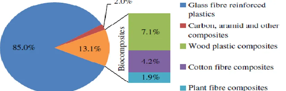
Figure 2.4: PFRPs accounted for 1.9% of the 2.4 million tonne EU FRP market in 2010 ... 13
Figure 2.5: Use of fiber-reinforced polymer composites in Boing 787 ... 14
Figure 3.1: A thin fiber-reinforced laminated composite subjected to in plane loading ... 18
Figure 3.2: Coordinate locations of plies in a laminate ... 18
Figure 3.3: Resultant forces and moments on a laminate ... 20
Figure 3.4: Geometry, coordinate system, and simply supported boundary conditions for a rectangular plate ... 23
Figure 4.1: Flowchart of the DE algorithm ... 28
Figure 4.2: Flowchart of the NM algorithm ... 29
Figure 4.3: Flowchart of the RS algorithm ... 31
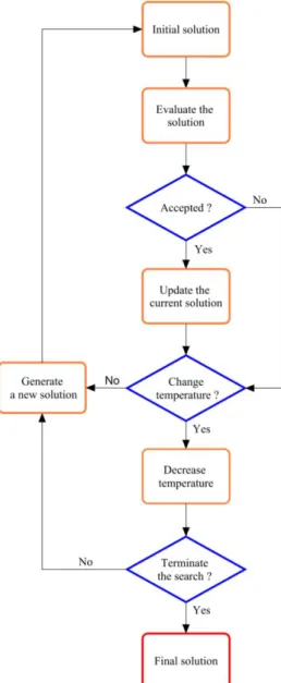
Figure 4.4: Flowchart of the SA algorithm ... 32
Figure 5.1: Laminated plate consisting of multiple laminate ... 34
Figure 6.1: Fundamental frequency and cost of laminated composite for 28 and 48 ply depends on aspect ratio and number of graphite ply ... 57
Figure 6.2: Percent reduction of fundamental frequency and cost of laminated composite for 28 and 48 ply depends on aspect ratio and number of graphite ply ... 58
xi
ABSTRACT
Development of vibration performances of hybrid laminated
composite materials by using stochastic methods
In recent years, laminated composites are fairly utilized in marine, automotive, aerospace, military and other engineering applications because of their high specific modulus (ratio between the young modulus and the density) and high specific strength (ratio between strength and density). In addition to these features, fiber reinforced composites have inherent tailorability such as fiber orientation and stacking sequence and provide great possibilities to designers against isotropic materials. Determination of the fundamental frequency performance of laminated composite plate is crucial for the design of the composite structures. Especially, in dynamical engineering systems, fundamental frequency have to be taken into account in order to prevent resonance arising from external excitations. Laminated composite materials can fulfill this requirement with an appropriate stacking sequence by using optimization methods.
In this thesis, the optimum designs of non-hybrid and hybrid laminated composite plates have been investigated. The considered laminated plate is simply supported on four sides. In non-hybrid cases, fundamental frequency is taken as objective function and fiber orientation angles of the laminated composites are taken as discrete and continuous design variables. The optimization has been conducted using graphite/epoxy, glass/epoxy and flax/epoxy materials for various aspect ratios (0.2-2). Single objective optimization formulation have been used for mathematical verification of model problems. In hybrid cases, multi objective approach is considered to maximize the fundamental frequency and minimize the cost simultaneously. The design variables of the multi objective optimization problems are selected as fiber orientation angles, the number of outer layers (No) having high-stiffness and more expensive and the number of inner layers (Ni ) having low-stiffness and inexpensive. Multi objective optimization has been carried out using hybrid graphite-glass/epoxy and graphite-flax/epoxy materials for various aspect ratios (0.2-2).
Ecological approach in automotive, aerospace and marine industries have stated that natural fibers (especially flax) are of great importance for their use as alternative reinforcing materials to glass fibers because of their inherent good vibration and cost
xii
performances. In this regard, the present study is an attempt to show the usage of flax fiber as an alternative to E-glass in interply hybrid composite structures in terms of fundamental frequency and cost. Stacking sequences design and optimization of laminated composites based on Differential Evolution (DE), Nelder Mead (NM), Random Search (RS) and Simulated Annealing (SA) algorithms are considered. The results show that the proposed optimum graphite-flax/epoxy interply composite structure give better than the result of graphite-glass/epoxy in terms of maximum fundamental frequency and minimum cost. It is also found that DE, NM and SA algorithms show superior or at least comparable performance versus Ant Colony Optimization (ACO), Simulated Annealing (SA) and Genetic Algorithm (GA) in the literature for the same laminated structure design problems.
xiii
ÖZET
Tabakalı hibrit kompozit malzemelerin titreşim performanslarının
stokastik optimizasyon yöntemleri kullanılarak geliştirilmesi
Son yıllarda, fiber katkılı tabakalı kompozitler, yüksek özgül modülü (elastisite modülü ve yoğunluk arasındaki oran) ve yüksek özgül mukavemeti (mukavemet ile yoğunluk arasındaki oran) nedeniyle deniz, havacılık, otomotiv ve diğer mühendislik uygulamalarında sıklıkla kullanılmaktadır. Bu özelliklere ek olarak, fiber takviyeli tabakalı kompozit malzemeler, fiber oryantasyonu ve tabaka dizilimi gibi doğal özelliklere sahiptir ve tasarımcılara izotropik malzemelere karşı büyük avantajlar sağlar. Kompozit plakaların doğal frekans performansının belirlenmesi, kompozit yapıların tasarımı için oldukça önemlidir. Özellikle, dinamik mühendislik sistemlerinde, dış yüklemelerden kaynaklanan rezonansı önlemek için doğal frekans dikkate alınmalıdır. Tabakalı kompozit malzemelerde optimizasyon yöntemleri kullanarak uygun tabaka dizilimlerinde arzulanan doğal frekans değerleri elde edilebilir.
Bu tezde, hibrid ve hibrit olmayan tabakalı kompozit plakaların optimum tasarımları araştırılmıştır. Düşünülen tabakalı kompozit plaka dört kenarından basit mesnet ile desteklenmektedir. Hibrid olmayan durumlarda, doğal frekans amaç fonksiyon olarak, tabakalı kompozitlerin fiber yönlenme açısı ise tasarım değişkeni olarak alınır. Optimizasyon, grafit / epoksi, cam / epoksi ve keten / epoksi malzemeler kullanılarak, çeşitli en-boy oranlarındaki (0.2-2) diktörtgen plakalar için gerçekleştirilmiştir. Model problemlerinin matematiksel doğrulanması için tek amaçlı optimizasyon yöntemi kullanılmıştır. Hibrit durumlarda, çok amaçlı optimizasyon yaklaşımı, temel frekansı en üst düzeye çıkarmak ve aynı anda maliyeti en aza indirgemek için düşünülmüştür. Çok amaçlı optimizasyon problemlerinde; fiber oryantasyon açıları, yüksek rijitliğe sahip ve pahalı dış katmanların (No) sayısı ve düşük rijitliğe sahip ve ucuz iç katmanların (Ni) sayısı tasarım değişkenleri olarak seçilirmiştir. Çeşitli en boy oranlarında ki (0.2-2) diktörtgen plakalar için hibrit grafit-cam / epoksi ve grafit-keten / epoksi malzemeleri kullanılarak çok amaçlı optimizasyon yapılmıştır.
Otomotiv, havacılık ve denizcilik endüstrilerinde ki çevreci yaklaşımlar, doğal elyafların (özellikle keten) doğal frekans ve maliyet performanslarından dolayı cam elyaflara alternatif takviye malzemeleri olarak kullanılmasının büyük önem taşıdıgını
xiv
ifade etmektedir. Bu bağlamda, bu çalışma, doğal frekans ve maliyet açısından, tabakalar arası hibrit kompozit yapılarda alternative malzeme olarak cam elyaf yerine keten elyaf kullanımını göstermektedir. Tabakalı kompozitlerin dizayn ve optimizasyonu Differential Evolution (DE), Nelder Mead (NM), Random Search (RS) ve Simulated Annealing (SA) algoritmaları yardımıyla yapılmıştır. Önerilen optimum grafit-keten / epoksi kompozit yapı, maksimum doğal frekans ve minimum maliyet açısından grafit-cam / epoksi yapıdan daha iyi sonuçlar vermiştir. Aynı tabakalı yapı tasarımı problemleri için DE, NM ve SA algoritmaları literatürdeki Ant Colony algoritması (ACO), Simulated Annealing (SA) ve Genetic Algoritma (GA) karşısında üstün veya en azından benzer performans göstermiştir.
1
CHAPTER 1
INTRODUCTION
1.1
Literature Survey
Laminated composites are fairly used in automotive, marine, aerospace and other engineering applications because of their inherent tailorability. Traditional fiber reinforced composite materials generally have consisted of glass, carbon and /or combination of these. In addition to being strong and rigid, when these materials are mixed, they save up cost and weight. However, in recent years, automobile, aircraft and construction industries focus on eco-friendly materials including cheaper, lightweight and high mechanical properties (Prabhakaran et al., 2014). Flax fiber is one of the natural fibers having high specific strength and low density and they can be used as an alternative to glass fiber in a composite system. A detailed discussion about the usage of flax fiber instead of glass in terms of vibration damping, cost efficiency, fracture toughness and fatigue behavior can be found in (Prabhakaran et al., 2014; Duc et al., 2014; Dittenber and Gangarao, 2012; Zhang et al., 2013; Liang et al., 2012). In the literature, even though mechanical properties of flax fiber are handled by researchers, there are only few studies concerning damping and vibration capabilities.
In recent years, it is possible to obtain appropriate designs including desired physical features of anisotropic materials with the development of stochastic optimization methods. In this regard, the design of some engineering structures sometimes necessitates the maximization or minimization of the objective function for the process. For example, maximizing the natural frequency (Reiss and Ramachandran, 1987; Fukunago et al., 1987; Narita, 2003, 2006; Karakaya and Soykasap, 2011; Lakshmi and Rao, 2015), maximizing critical buckling load factor (Le Riche and Haftka, 1992; Erdal and Sonmez, 2005; Soykasap and Karakaya, 2007; Karakaya and Soykasap, 2009), dimensional stability (Aydin, 2011; Aydin et al., 2015, 2016; Bressan et al., 2004; Le Riche and Gaudin, 1998), minimization of failure index
2
(Groenwold and Haftka, 2006; Lopez et al., 2009) are used in developing new materials systematically. However, the design and optimization of the engineering structures need to be maximized and / or minimized frequently conflicting more than one objectives, simultaneously. In this situation, multi-objective approach is used and Pareto optimal solutions are gained. There are several examples on the multi objective optimization problems for laminated composites in the literature in terms of cost-weight (Abachizadeh and Tahani, 2007; Hemmatian et al., 2013; Rao and Lakshmi, 2011), frequency-cost (Tahani et al., 2005), strength-mass (Pelletier and Vel, 2006), weight-cost-failure load (Ghasemi and Ehsani, 2007), deflection-weight (Walker et al., 1998), stiffness-thermal expansion coefficient, critical buckling load- critical temperature rise and failure load (Spallino and Rizzo, 2002), weight, buckling and failure load factor (Irisarri et al., 2009). In this approach, it is not possible to obtain the best solution for all objectives, thus only one solution is selected from the set of solutions for practical engineering usage. (Aydin and Artem, 2011).
In dynamical engineering systems, fundamental frequency is an important issue in order to prevent resonance arising from external excitations, therefore many researchers have solved fundamental frequency optimization problems including practical applications of engineering. Reiss and Ramachandran (1987), Bert (1977) and Grenestedt (1989) investigated the maximum fundamental frequency for laminated composite plates based on single objective approach by continuous design variables. Duffy and Adali (1991) solved the same problem for cross ply laminates. Qatu (1991) inquired effects of material type, fiber orientation and edge conditions on the natural frequency and mode shapes for symmetric laminated composite plates by using Ritz method. Narita and Leissa (1992) handled free vibration problem for cantilever and rectangular angle-ply and cross-ply laminated composite plates using Ritz method.Narita (2006) used combined LO-FEM (layerwise optimization and finite element analysis) approach to determine free vibration behavior of symmetric laminated rectangular and square plates with mixed boundary conditions. Topal (2012) tackled the applicability of extended layerwise optimization method (ELOM) to maximize the fundamental frequency of laminated composite plates with various aspect ratios and mixed boundary conditions. The first order shear deformation theory (FSDT) is utilized for the finite element solution of the laminated composites. Khdeir and Reddy (1999) proposed a complete set of linear equations for cross-ply
3
and angle-ply laminated plates concerning free vibration utilizing second order shear deformation theory and gained analytical solutions with arbitrary boundary conditions for thin and moderately thick plates. Cong et al. (2011) investigated effect of cutout upon natural frequency and mode shape for cross-ply laminated composite plates with different aspect ratios and boundary conditions using first order shear deformation theory.
In addition to mechanical point of view of laminated composite structures, it is also crucial to consider the cost and weight factors in engineering problems. Therefore, fundamental frequency, weight and cost of the structures can be preferred as an objective functions of the design and optimization problems. This attempt can be achieved either by multi objective or single objective approaches. For instance, by single objective approach: Adali and Duffy (1992) viewed minimum cost design of antisymmetric, angle-ply hybrid laminates under fundamental frequency constraint. Adali and Verijenko (2001) deal with fundamental frequency, frequency separation and cost factor for graphite-glass/epoxy symmetric interply hybrid laminates and determined the optimum discrete stacking sequence design. Moreover, it should be noted that interply hybrid laminated construction involves high-stiffness and expensive material in the surface layers and low-stiffness and cheap one in inner layers. This type of construction provides both suitable structural rigidity and low cost simultaneously. Therefore, multi objective optimization approach is usually preferred in the solution of the design problems for interply hybrid laminated composites. The previous studies about multi objective optimization problems in interply hybrid laminated composite exhibit that the designers can reduce cost and weight of laminated composite as well as providing safer design . In this regard, Abachizadeh and Tahani (2009) solved multi objective optimization problem of composite graphite-glass/epoxy symmetric interply hybrid laminates for maximum fundamental frequency and minimum cost. Beluch et al. (2007) determined optimum stacking sequence and the number of inner and outer layers for graphite-glass/epoxy interply hybrid structure in terms of minimum cost and maximum fundamental frequency and frequency seperations. Grosset et al. (2001) carried out minimum cost-weight design under frequency constraint. Baier et al. (2008) dealed with combined continuous-discrete optimization problem using geometry and material parameters on the o side of plate. The Pareto set optimal solution is obtained for composite satellite equipment in terms of minimum mass and high resonance
4
frequency. Design and optimization problems of laminated composites include complicated, highly nonlinear functions, hence stochastic optimization methods such as Genetic Algorithm and Simulated Annealing become appropriate to solve them. Genetic Algorithm is used for stacking sequence optimization of laminated composites for maximum buckling load under contiguity and strain failure constraints (Le Riche and Haftka, 1992), for maximum fundamental frequency of laminated plate with different edge conditions (Apalak et al., 2008), for minimum weight of laminated composites under strength and stiffness constraints (Callahan and Weeks, 1992) and maximizing the twisting displacement of a cantilevered composite plate under contiguity and failure constraints (Soremekun et al., 2001). Simulated Annealing Algorithm is preferred in the solution of natural frequency and buckling optimization problems (Karakaya and Soykasap, 2011), for maximum natural frequency with buckling torque and torsional strength constraints and minimum weight with frequency constraint (Gubran and Gupta, 2002), for minimum weight optimization of laminated composite plates subjecting to different in-plane loadings considering Tsai-Wu and the maximum stress failure criteria (Akbulut and Sonmez, 2008). Apart from GA and SA, Random seach method is used for weight minimization satisfying failure criteria (Fang and Springer, 1993) and to determine the effects of uncertain material properties on the buckling behavior of laminated composites (Nguyen, 2017). Differential Evolution method is preferred to find the optimum stacking sequence for symmetric and unsymmetric laminated composite plates with simply supported and clamped boundaries considering maximum natural frequency and constant stiffness (Roque and Martins, 2017), for maximum buckling load factor of laminated composite using integer and continuous design variables (Ho-Huu et al., 2016). By considering the literature on laminated composite design, it is seen that optimum natural frequency maximization studies have a wide range of area based on the stochastic optimization methods. In this regard, the studies on Ant Colony Algorithm including minimum cost (Abachizadeh and Tahani, 2009), Evolutionary Strategy Algorithms involving minimum mass (Baier et al., 2008), multi objective evolutionary algorithm including minimum cost (Beluchi et al., 2007), Modified feasible direction (MFD) method, Golden section method (GS) (Topal and Uzman, 2008) and discrete singular convolution (DSC) method (Civelek, 2008) for different boundary condition, Discrete hybrid PSO algorithm (Rao and Lakshmi, 2011) regarding minimum cost and weight, Differential Evolution method
5
considering minimum weight as second objective function (Vo-Duy et al., 2017), Globalize Bounded Nelder Mead Method (GBNM) (Ameri et al., 2012) can be found in the literature. Moreover, some researchers compared different stochastic optimization methods such as Genetic Algorithm, Simulated Annealing and Generalized Pattern Search for laminated composite optimization problems (Aydin and Artem, 2011; Hasancebi et al., 2010; Manoharan et al., 1999).
1.2 Objectives
In this study, stacking sequence design and optimization of laminated composite plates for maximum fundamental frequency and minimum cost are determined using stochastic optimization methods: Differential Evolution (DE), Nelder Mead (NM), Simulated Annealing (SA) and Random Search (RS). Simply supported symmetric and symmetric- balanced composite plates with constant total thickness (2mm) and different aspect ratios (length to width) are considered. Considered composite plates consist non hybrid (graphite/epoxy, glass/epoxy, flax/epoxy) and hybrid (graphite-glass/epoxy, graphite-flax/epoxy) structures. Fiber orientation angle, the numbers and the thicknesses of the surface and core layers are taken as design variables. The aim of this thesis can be listed as follows;
• To maximize fundamental frequency and minimize cost simultaneously.
• Comparison of the stacking sequence designs of laminated composites for different aspect ratios using stochastic methods DE, NM, SA, RS.
• Comparison of discrete and continuous stacking sequences designs for the same laminated composite structure design and optimization problems.
• Determination of performance of hybrid structures consisting high stiffness in surface layers and low stiffnes in core layers in terms of fundamental frequency and cost.
• To research the usage of flax fiber, one of the natural fiber instead of glass fibres as reinforcement in composites for fundamental frequency maximization problems.
• Comparison of performance of the proposed algorithms (DE, NM, SA, RS) with popular algorithms (Ant Colony, Genetic Algorithm, Simulated Annealing) used in literatures.
6
CHAPTER 2
COMPOSITE MATERIALS
2.1
Introduction
In general terms, a composite can be describe as a structural material which comprises two or more components that are compounded at macroscopic level and are not soluble in each other. These components are called the reinforcement phase and the matrix. The reinforcement material can be in the form of particles, sheets, fibers or distinct other geometries. The matrix materials are usually in continuous nature. Epoxy reinforced with carbon fibers and concrete reinforced with steel, etc. are some composite system examples (Kaw, 2006).
The usage of composite materials have continued for many centuries. For example, the ancient Egyptian workers utilized chopped straw in bricks during the construction of pyramids to improve their structural integrity. Eskimos used moss to carry out strength ice homes. The Japanese Samurai warriors utilized multilayered metals in the forging of their swords to supply admirable material properties. In the 20th century, civil engineers place construction iron into cement and manufactured a well-known composite material, i.e., reinforced concrete. It can be said that the modern times of composite materials started with the use of fiberglass polymer matrix composites during World War II (Vinson and Sierakowski, 2004).
Fiber-reinforced composite materials have low density, high specific modulus (ratio between the young modulus and the density) and specific strength (ratio between strength and density). In addition to these natural features, these materials include some important design parameters to be able to tailored and provided advantage to against conventional isotropic materials such as ply orientation and stacking sequence. Thus, fiber-reinforced composite materials are fairly utilized instead of metals in aerospace, automotive, marine and other branches of engineering applications.
7
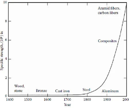
Figure 2.1 shows the usage of fibers, composites and the other traditional materials in terms of specific strength on annual basis.
Figure 2.1 : Specific strength as a function of time of use of materials (Source: Kaw 2006)
Table 2.1 shows that specific strength and specific modulus properties for commonly utilized composite fibers, unidirectional composites, cross-ply and quasi-isotropic laminated composites and monolithic metals. (Kaw, 2006).
Table 2.1 : Specific Modulus and Specific Strength Values of Typical Fibers, Composites and Bulk Metals (Source: Kaw 2006)
Materials Units Specific Gravity Young’s Modulus (GPa) Ultimate Strength (MPa) Specific Modulus (GPa-m3/kg) Specific Strength (MPa-m3/kg) System of Units: SI Graphite fiber 1.8 230 2067 0.1278 1.148 Aramid fiber 1.4 124 1379 0.08857 0.9850 Glass fiber 2.5 85 1550 0.0340 0.6200 Unidirectional graphite/epoxy 1.6 181 1500 0.1131 0.9377 Unidirectional glass/epoxy 1.8 38.60 1062 0.02144 0.5900 Cross-ply graphite/epoxy 1.6 95.98 373 0.06000 0.2331 Cross-ply glass/epoxy 1.8 23.58 88.25 0.01310 0.0490 Quasi-isotropic graphite/epoxy 1.6 69.64 276.48 0.04353 0.1728 Quasi-isotropic glass/epoxy 1.8 18.96 73.08 0.01053 0.0406 Steel 7.8 206.84 648.10 0.02652 0.08309 Aluminum 2.6 68.95 275.80 0.02652 0.1061
8
2.2
Classification of Composites
Composites can be classified either the geometry of the reinforcement material such as particulate, flake and fibers (Figure 2.2) or the type of matrix such as metal, ceramic, carbon and polymer.
Figure 2.2 : Types of composites based on reinforcement shape (Source: Kaw 2006)
Particulate composites comprise inserted particles in matrices such as alloys and ceramics. As the particles disperse randomly in matrices, they can be supposed as isotropic. These composites have some advantages such that advanced strength, enhanced operating temperature, and oxidation resistance. The usage of aluminum particles in rubber; silicon carbide particles in aluminum; and gravel, sand, and cement to conduct concrete are common examples of them (Kaw, 2006).
Flake composites comprise of thin, flat reinforcements suspended in matrices. Aluminum, glass, mica and silver can be utilized as flake materials in composites. Main advantages of the usage of flake composites in structure are higher strength and out-of-plane flexural modulus and low cost. On the other hand, these composites have some drawbacks. For instance, flakes cannot be directed easily and only a few number of materials are appropriate for use (Kaw, 2006).
Fiber composites comprise matrices, reinforced fibers and an interface. Fibers consists of either short (discontinuous) type or long (continuous) type fiber having high aspect ratio . Carbon, graphite, boron, kevlar and aramids can be chosen as fibers for composites.
9
Metals such as titanium, aluminum or magnesium; ceramics such as calcium– alumina silicate and resins such as epoxy, vinylester, polyester are instances of matrices. Continuous fiber matrix composite materials contain unidirectional or woven fiber laminas. Laminas are piled up top of each other at diverse angles to make up a multidirectional laminate (Kaw, 2006).
The most widely used advanced composites are polymer matrix composites (PMCs) comprising of a polymer such as epoxy, polyester and urethane, reinforced by thin diameter fibers such as graphite, glass, boron and aramid. These composites are mostly preferred because of their low cost, high strength, and simple manufacturing principles. The main disadvantages of PMCs are low operating temperatures, high coefficients of thermal and moisture expansion and low elastic properties in certain directions.
Graphite and glass fibers in polymer matrix composite are used wide range of engineering applications. Graphite fibers are more often used in high-modulus and high-strength applications such as aircraft components, etc. They have low coefficient of thermal expansion, and high fatigue strength. The disadvantages are high cost, low impact resistance, and high electrical conductivity. Especially, high cost restricts the usage of this material without special applications. To overcome this disadvantage, glass fibers are used together with graphite in hybrid structure. In this way, it can be provided that both suitable structural rigidity and low cost. In addition to low cost, glass fiber has advantages that high strength and chemical resistance, good insulating properties. The disadvantages are low elastic modulus, poor adhesion to polymers, high specific gravity, sensitivity to abrasion (reduces tensile strength) and low fatigue strength. The main types of glass fibers are E-glass (fiberglass) used for electrical and structural applications, S-glass included higher content of silica and keep its strength at high temperatures. Other typies of glass fiber are C-glass (Corrosion) prefered in chemical environments, R-glass utilized in structural applications, D-glass (Dielectric) can be used applications entailing low dielectric constants and A-glass (Appearance) utilized to improve surface appearance.
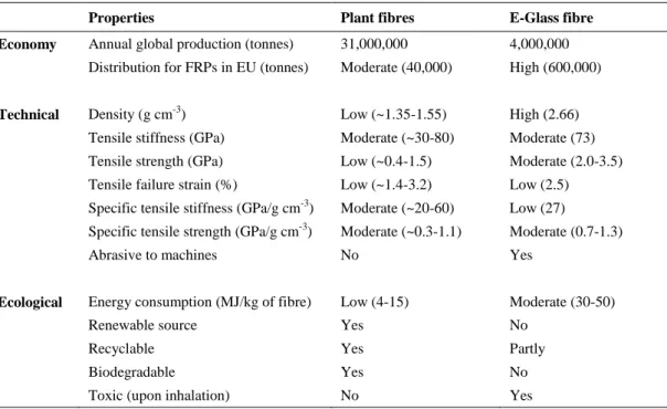
Natural fibres present several economical, technical and ecological advantages compared to synthetic fibres in reinforcing polymer composites because of low density and cost, high specific properties, health advantages, recyclability and eco-friently profile. Such as flax, hemp and jute, natural fibers have been prefered as alternative reinforcing materials to synthetic fibers, specifically E-glass (Shah et al.,
10
2012; Wambua et al., 2003; Faruk et al., 2012). Comprasion of different properties between natural fibers and E-glass fiber are indicated in Table 2.2.
Table 2.2 : Comparison between plant fibers and E-glass (Source: Shah et al., 2013)
Properties Plant fibres E-Glass fibre
Economy Annual global production (tonnes) 31,000,000 4,000,000
Distribution for FRPs in EU (tonnes) Moderate (40,000) High (600,000)
Technical Density (g cm-3) Low (~1.35-1.55) High (2.66)
Tensile stiffness (GPa) Moderate (~30-80) Moderate (73) Tensile strength (GPa) Low (~0.4-1.5) Moderate (2.0-3.5) Tensile failure strain (%) Low (~1.4-3.2) Low (2.5) Specific tensile stiffness (GPa/g cm-3) Moderate (~20-60) Low (27)
Specific tensile strength (GPa/g cm-3) Moderate (~0.3-1.1) Moderate (0.7-1.3)
Abrasive to machines No Yes
Ecological Energy consumption (MJ/kg of fibre) Low (4-15) Moderate (30-50)
Renewable source Yes No
Recyclable Yes Partly
Biodegradable Yes No
Toxic (upon inhalation) No Yes
It is thinked that natural fibres cause less health problems for the people working composites production and these materials do not lead to skin irritations and lung cancer. This is important issue because the discussion about whether or not small glass fibres can lead to lung cancer, has still not finished. The large amount of dust that occurs in the preliminary phase of the flax fiber insulation process can be relatively controlled in the modern flax fiber processing industry (Bos, 2004).
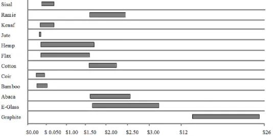
In addition to being healthy, natural fibers are lower cost and weight than synthetic fibers.For the aerospace, military and automotive industry, weight and cost reduction without sacrificing from mechanical properties is an always important issue. The usage of natural fibers as fillers meets this need. The cost of some natural fiber, glass and graphite fiber are shown in Figure 2.3.
11
Figure 2.3 : Cost per weight comparison between glass, graphite and natural fibres (Dittenber et al., 2012)
There are several polymers used in advanced polymer composites classified thermoset (epoxies, polyesters, phenolics, and polyamide) and thermoplastic (polyethylene, polystyrene, polyether–ether–ketone (PEEK) and polyphenylene sulfide (PPS)). Thermoset polymers connected strong covalent bonds are insoluble and infusible after cure; thermoplastics include weak van der Waals bonds and thus they can be formed at high pressure and high temperatures. The diversities between thermosets and thermoplastics are denoted in Table 2.3 (Kaw, 2006).
Table 2.3 : Differences between thermosets and thermoplastics (Source: Kaw, 2006)
Thermoplastics Thermosets
Soften on heating and pressure, and thus easy to repair Decompose on heating High strains to failure Low strains to failure Indefinite shelf life Definite shelf life Can be reprocessed Cannot be reprocessed Not tacky and easy to handle Tacky
Short cure cycles Long cure cycles
Higher fabrication temperature and viscosities have made it difficult to process
Lower fabrication temperature Excellent solvent resistance Fair solvent resistance
Epoxy resins are the most commonly used thermoset PMC, nevertheless they are more expensive than other polymer matrices. Epoxy matrices have some advantages such as high strength, low viscosity and low flow rates that permit good wetting of fibers and prevent misalignment of fibers during processing, low evaporation during cure, low shrinkage, which decrease the tendency of obtaining large shear stresses of
12
the bond between epoxy and its reinforcement and so they are usable for a wide range of engineering applications.
Metal matrix composites (MMCs) comprise of metals or alloys (aluminum, magnesium, titanium, copper) reinforced with carbon (graphite), boron or ceramic fibers. The materials are commonly used to provide advantages over metals such as steel and aluminum. The main advantages of these composites can be listed as higher specific modulus and strength by low density metals such as aluminum and titanium, lower coefficients of thermal expansion, such as graphite.
Ceramic matrix composites (CMCs) include ceramic matrices (alumina calcium, silicon carbide, aluminum oxide, glass-ceramic, silicon nitride) reinforced with ceramic fibers. The main advantages of CMCs are high strength, hardness, high service temperature limits for ceramics, chemical inertness and low density. Nevertheless ceramic matrix composites have low fracture toughness.
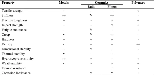
Carbon-carbon composites (C/C) contain carbon fibers reinforcement in the carbon or graphite matrix. This type of composites have excellent properties of high strength at high temperature, low thermal expansion and density. Disadvantages of C/C composites are their high cost, low shear strength, and sensitivity to oxidations at high temperatures. Typical properties of conventional matrix materials are given as comparative with each other in Table 2.4 and Table 2.5, each type of matrix and fiber has their advantages and drawbacks.
Table 2.4 : Comparison of Conventional Matrix Materials (Source: Daniel and Ishai, 2005)
Property Metals Ceramics Polymers
Bulk Fibers Tensile strength + - ++ v Stiffness ++ V ++ - Fracture toughness + - v + Impact strength + - v + Fatigue endurance + V + + Creep v V ++ - Hardness + + + - Density - + + ++ Dimensional stability + v + - Thermal stability v + ++ - Hygroscopic sensitivity ++ v + v Weatherability v v v + Erosion resistance + + + - Corrosion Resistance - v v +
13
Table 2.5 : Advantages and disadvantages of reinforcing fibers (Source: Daniel and Ishai, 2005)
Fiber Advantages Disadvantages
E-glass, S-glass High strength Low cost
Low stiffness Short fatigue life
High temperature sensitivity Aramid (Kevlar) High tensile strength
Low density
Low compressive strength High moisture absorption
Boron High stiffness
High compressive strength
High cost Carbon (AS4, T300, C6000) High strength
High stiffness
Moderately high cost Graphite (GY-70, pitch) Very high stiffness Low strength
High cost Ceramic ( silicon carbide, alumina) High stiffness
High use temperature
Low strength High cost
2.3
Applications of Composite Materials
Fiber-reinforced polymer composites are utilized in various engineering fields since they have better combination of strength and modulus than traditional monolithic metal materials. The application fields of composite materials are aircraft, space, automotive, boats and marine, sporting goods, medical industry and military. Figure 2.4 indicates the relative market share of EU for synthetic and natural fiber composites and it is seen that the most commonly used fiber in composite industry is glass. Composite materials such as carbon, aramid are only used in special applications due to their high prices. For instance, these composites are frequently utilized in the field of military and commercial aircrafts as these materials can provide both lightweight and strength.
Figure 2.4 : PFRPs accounted for 1.9% of the 2.4 million tonne EU FRP market in 2010 (Source: Carus, 2011)
14
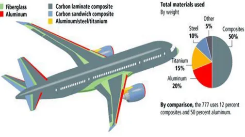
The more lightweight aircraft is the less burn fuel, thus weight minimization is important for military and commercial aircrafts. Figure 2.5 illustrates usage of composite materials in various components of the Boeing 787 aircraft. Carbon fibers are familiarized (acquaint) to industry in the 1970s and carbon- epoxy has been used as the primary material in many wing, empennage and fuselage components. The structural integrity and durability of constituent have enhanced confidence in their performance and developments of other structural aircraft constituents, thus increasing amount of composite materials are utilized in military aircrafts. For instance, the F-22 fighter aircraft have also 25% by weight of carbon fiber reinforced polymers; the other materials are titanium (39%) and aluminum (16%). The stealth aircrafts are almost all made of carbon fiber-reinforced polymers on account of design features that contain special coatings, decrease radar reflection and heat radiation. Moreover, many fiber-reinforced polymers are used in military and commercial helicopters for conducting baggage doors, fairings, vertical fins, tail rotor spars and so on (Mallick, 2007).
Figure 2.5 : Use of fiber-reinforced polymer composites in Boing 787 (Source: Bintang, 2011)
Another important application for composite materials is an automotive industry. Body, chassis and engine constituent are three major constituent in automotive industry. Body constituent such as the hood or door panels necessitate high stiffness and damage tolerance (dent resistance), thus the composite material used for these constitutes is E-glass fiber-reinforced sheet molding compound (SMC) composites. E-glass fiber is utilized instead of carbon fiber due to its considerably
15
lower cost. For the chasis constituent, the first main structural application of reinforced composites is rear leaf spring. The usage of unileaf E-glass fiber-reinforced epoxy springs instead of multileaf steel springs provide approximately 80% weight reduction. Other chassis constituent, such as drive shafts and wheels have been successfully tested, but they have been manufactured in limited quantities. The application of fiber reinforced composites in engine constituent has not been as successful as the other constituent (Mallick, 2007).
Nowadays, the usage of natural fibres instead of glass fibres as reinforcement in composites for engineering applications has obtained popularity because of an increasing environmental anxiety and necessity for developing sustainable materials. Approximately 315,000 tonnes of natural fibres were used as reinforcement in composites in the European Union (EU) in 2010, which are constituted for 13% of the total reinforcement materials (glass, carbon and natural fibres) in fibre reinforced composites (Yan et al., 2014). By commercial application, over 95% of PFRPs produced in the EU are used for non-structural automotive components. Table 2.6 shows the usage of natural fibers in automative part.
16
Actually, the automotive industry utilizes wood fibres as fillers. Wood reinforced fibres are quite short and this materials provide stiffer composites, however, they do not conduct them stronger. Thus, later, other longer reinforced natural cellulose fibres like flax, jute, hemp and sisal were developed for otomativ application.
Without automotive applications, natural fibers are used for interior components such as instrumental panels and door, they are used for applications in infrastructure and construction such as bridges, roof panels, beams,; sports equipments such as boat hulls, canoes, tennis rackets, bicycle frames; consumer and furniture goods such as packaging, chairs, cases, urns, tables, helmets, ironing boards.
17
CHAPTER 3
MECHANICS OF COMPOSITE MATERIALS
The mechanics of materials takes into consideration the concepts of stresses, strains, and deformations in engineering structures subjected to mechanical and environmental effects for instance moisture, temperature and radiation. A common consideration for mechanics of traditional engineering materials such as stainless steel, metal, copper, bronze and lead is that, this materials are homogeneous and isotropic. Their properties are independed of location and orientation. On the contrary, fiber reinforced composite materials are inhomogeneous and non-isotropic (orthotropic). As a result of this, the mechanical analysis of fiber-reinforced composite materials are much more sophisticated than that of traditional materials (Mallick, 2007).Fiber reinforced composite materials can be analyzed in two distinct levels: (i) macromechanical analysis and (ii) micromechanical analysis. These terms can be explained as follow.
Micromechanics: Mechanical analysis of the interactions of the components are microscopic level. This study is usually conducted by means of a mathematical model defining the response of each component material.
Macromechanics: In this analysis, material is assumed homogeneous. Mechanical analysis of the interactions of the components and their effects of interactions on the overall response quantities of the laminate are investigated in macroscopic level. At the laminate level, the macromechanical analysis is utilized in the form of lamination theory to analyze whole behaviour as a function of lamina properties and stacking sequence (Daniel and Ishai, 2005).
3.1
Classical Lamination Theory
Classical laminated plate theory is applied to define mechanical behaviour of laminated composites. This theory is only used in the following assumptions
18
1. Each lamina is homogeneous and orthotropic.
2. Each lamina is elastic and perfectly bounded each other.
3. The laminated composite is thin and the thickness of composite plate are much lesser than its edge dimensions.
4. The loadings are only implemented in the laminate's plane and the laminated composite (except for their edges) is subjected to plane stress (σzτxz= τyz=0). 5. Displacements are small constrast with the thickness of the laminate and
they are continuous throughout the laminate.
6. In plane displacements in the x and y directions are linear functions of z. 7. Transverse shear strains (γxz and γyz ) are ignorable because a line straight
and perpendicular to the middle surface preserves state throughout deformation.
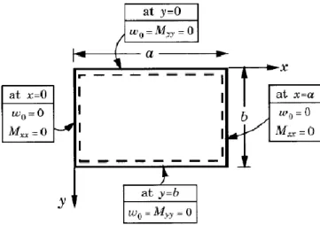
Considered thin laminated composite plate in this thesis is shown in Figure 3.1. Global coordinates of the layered material are defined x, y and z. A layer-wise principal material coordinate system is indicated by 1, 2, 3 and fiber direction is oriented at angle . Representation of laminate convention for the n-layered structure with total thickness h is given in Figure 3.2.
Figure 3.1 : A thin fiber-reinforced laminated composite
Figure 3.2 : Coordinate locations of plies in a laminate (Source: Kaw, 2006)
19
The strains at any point in the laminate to the reference plane can be written as
o x x x o y y y s s s z (3.1)
The stress-strain relationship for the k-th layer of a laminated composite plate considering the classical lamination theory can be written in the following form
k xy y x o xy o y o x k k xy y x z Q Q Q Q Q Q Q Q Q 66 26 16 26 22 12 16 12 11 (3.2)
where [Qij]k are the in plane elements of the transformed reduced stiffness matrix under plane stress condition, [o] is the mid-plane strains, [
] is curvatures, respectively.The elements of transformed reduced stiffness matrix [Qij] can be expressed as in the following form
2 2 66 12 4 22 4 11 11 Q c Q s 2(Q 2Q )s c Q (3.3) ) ( ) 4 ( 11 22 66 2 2 12 4 4 12 Q Q Q s c Q c s Q (3.4) 2 2 66 12 4 22 4 11 22 Q s Q c 2(Q 2Q )s c Q (3.5) c s Q Q Q sc Q Q Q Q16 ( 11 12 2 66) 3 ( 22 12 2 66) 3 (3.6) 3 66 12 22 3 66 12 11 26 (Q Q 2Q )cs (Q Q 2Q )sc Q (3.7) ) ( ) 2 2 ( 11 22 12 66 2 2 66 4 4 66 Q Q Q Q s c Q c s Q (3.8)
20 where stiffness matrix quantities [Qij] are
12 21 1 11 1 E Q (3.9) 12 21 2 12 12 1 E Q (3.10) 12 21 2 22 1 E Q (3.11) 12 66 G Q (3.12)
Figure 3. 3 : Resultant forces and moments on a laminate (Source: Kaw, 2006)
Applied normal force resultants Nx,N , shear force resultanty N (per unit xy
width) and moment resultants Mx,M and y M on a laminate (Fig. 3.3) have the xy
following relations: xy y x xy y x xy y x B B B B B B B B B A A A A A A A A A N N N 66 26 16 26 22 12 16 12 11 0 0 0 66 26 16 26 22 12 16 12 11 (3.13) xy y x xy y x xy y x D D D D D D D D D B B B B B B B B B M M M 66 26 16 26 22 12 16 12 11 0 0 0 66 26 16 26 22 12 16 12 11 (3.14)
21
The matrices [A], [B] and [D] specified in Equations 3.13 and 3.14 can be defined as
n k ij k k k ij Q h h A 1 1 ) ( )] [( , i,j 1,2,6 (3.15) n k ij k k k ij Q h h B 1 2 1 2 ) ( )] [( 2 1 , i,j1,2,6 (3.16) n k ij k k k ij Q h h D 1 3 1 3 ) ( )] [( 3 1 , i, j1,2,6 (3.17)
The [A] matrice is extensional stiffness regarding plane forces to the in-plane strains, [B] matrice is coupling stiffness regarding forces and mid-in-plane strains, moments and mid-plane curvatures and [D] matrice is bending stiffness regarding moments and curvatures. (Kaw, 2006).
Now, stresses and strain expressions based on classical lamination theory can be expressed by local coordinate system (1, 2). The relation between the local and global stresses in an angled lamina can be written as in the following form:
xy y x T 12 2 1 (3.18)Similarly, the local and global strains are also related as follows
xy y x R T R 1 12 2 1 (3.19) where
2 0 0 0 1 0 0 0 1 R (3.20)22 and
T transform matrix, 2 2 2 2 2 2 2 2 ] [ s c sc sc sc c s sc s c T ccos, ssin (3.21)
3.2
Vibration Theory of Laminated Composite Plates
All elastic bodies begin to oscillate about their equilibrium position under the influence of an external stimulus and continue to oscillate when this stimulus is lifted. This oscillation is called free vibration motion. The total number of oscillations per minute is called natural frequency. This number of frequencies is endless for plates that are a continuous medium. The smallest of these frequencies is called the fundamental frequency. In the case of a external vibration force that is equal to any of these frequency values, the amplitude of the distance of the plate from its equilibrium position increases and goes to infinity. This is called as resonance. Therefore, knowing the frequency values in terms of design is very important in terms of enabling the engineering structure to operate without any damage. (Meirovitch, 1986). A vibration analysis usually includes four steps. First, the structure or system of interest is defined, its boundary conditions are predicted and its interfaces with other systems are plotted. Second, the natural frequencies and mode shapes of the structure are designated by analysis or direct experimental measurement. Third, the time dependent loads on the structure are predicted. Fourth, these loads are applied to an analytical model of the structure to specify its response. The major steps in the vibration analysis are the identification of the structure and the determination of its natural frequencies and mode shapes (Blevins, 1979). In this regard, simply supported laminated plate is considered and the governing equation of the free vibration process based on the classical laminated plate theory for the described symmetric laminate is given as follow (Reddy, 2004):
4 4 4 4 4 2 11 4 4 16 3 2 12 2 66 2 2 4 26 3 22 4 2 w w w w w w D D D D D D h x x y x y x y y t (3.22)23
where D11, D12, D16, D22, D26 , D66 are the terms of bending stiffnesses, w is the deflection in the z direction , h is the total thickness of the laminate , t is time and ρ is the mass density as
/2 1 ( ) ( ) /2 1 1 N h k k h k h dz N
(3.23) where N is the total number of plies, k is the ply number.The boundary conditions for the simply supported plate are given as ( , 0) 0, ( , ) 0, (0, ) 0, ( , ) 0 (0, ) 0, ( , ) 0, ( , 0) 0, ( , ) 0 xx xx yy yy w x w x b w y w a y M y M a y M x M x b (3.24)
Figure 3.4 : Geometry, coordinate system, and simply supported boundary conditions for a rectangular plate (Source: Reddy, 2004)
If the stacking sequence of laminated composite comprise only 0 and 90 degree , this laminate is called special orthotropic. For symmetric special orthotropic laminate, A16=A26=B=D16=D26 = 0, thus , no coupling occurs between the normal-shear forces, bending - twisting moments and force-moment terms. Nemeth (1986) has given the detail about bending–twisting interaction in composite laminates for buckling problems. In case laminated composite is not specially orthotropic, the effect of bending – twisting terms D and 16 D will be neglected if the non-26
dimensional parameters have the conditions:
0.2, 0.2
(3.25) where
24 3 1/4 16( 11 22) D D D 3 1/4 26( 11 22 ) D D D
Because of the similarity between buckling and free vibration analysis, the same constraints are used to reduce complexity of the problem.
The deflection w for the natural vibration mode (m , n) is obtained by solving the governing equation (Eq.3.22) with the boundary conditions (Eq.3.24) as :
1 1 ( , , ) sin sin i mnt mn m n m x n y w x y t A e a b
(3.26) where mn is the natural frequency of the vibrating mode (m , n) obtained by solvingan eigenvalue problem as
4 2 2 4 4 2 11 2 12 2 66 22 mn m m n n D D D D h a a b b (3.27)Here, different values of m and n give different mode shapes of the laminated plate. Clearly, fundamental frequency can be obtained with the condition m=n=1.
25
CHAPTER 4
OPTIMIZATION
Optimization can be identified as mathematical process used forming the best design or favorable designs by minimizing or maximizing defined single or multi objectives that fulfill all the constraints. Optimization is frequently used in engineering problems such as weight, cost, vibration, buckling and failure. In such problems, single and multi objective optimization approaches are utilized to obtain desired design of structure. In single objective optimization approach, design and optimization problem comprise of a single objective function, constraints and bounds. Nevertheless, the design and optimization of the engineering structures need to be maximized and / or minimized often conflicting more than one objectives, simultaneously. (Aydin and Artem, 2011). In this situation, multi-objective approach is used and Pareto optimal solutions are gained. In this approach, it is not possible to obtain the best solution for all objectives, thus only one solution is selected from the set of solutions for practical engineering usage (Pelletier and Vel, 2006).
As design and optimization problems of laminated composites include complicated, highly nonlinear functions, they are unsolvable by the traditional optimization methods. In these situation, the usage of stochastic optimization methods such as Differential Evolution (DE), Random Search (RS), Nelder Mead (NM), Simulated Annealing (SA) and Genetic Algorithms (GA) are appropriate.
MATHEMATICA is one of the crucial commercial program that can be used to solve the design and optimization problems for composites. The program includes stochastic methos Differential Evolution (DE), Nelder Mead (NM), Random Search (RS) and Simulated Annealing (SA) for solving optimization problems. All of these methods are used in the design and optimization of composite structures by many researchers.
26
4.1 Single objective optimization
Single objective optimization approach comprises objective function, design variables, constraints and bounds of constraints. In this study, the problems solved using single-objective optimization approach are expressed as follows
minimize f (1 ,2 ,....,n ) such that hi (1 ,2 ,....,n ) 0 i 1, 2,...r g j (1 ,2 ,....,n ) 0 j 1, 2,...m L ≤ 1,2 ,....,n ≤ U
where f is objective function, 1,2 ,....,n are the design variables and h, g are the
constraints of the problem. Here, L and U show lower and upper bounds. In design and optimization of composite structure problems; stiffness, mass, strength, displacements, thickness, vibration frequencies, buckling loads, residual stresses, cost and weight are utilized as objective functions (Gurdal et al., 1999). In this thesis, fundamental frequency is taken as objective function of the single-objective optimization problems.
4.2
Multi objective optimization
A multi-objective optimization problem can be expressed as follows: minimize f1 (1 ,2 ,....,n ), f2 (1 ,2 ,....,n ),…….. ft (1 ,2 ,....,n ) such that hi (1 ,2 ,....,n ) 0 i 1, 2,...r g j (1 ,2 ,....,n ) 0 j 1, 2,...m L ≤ 1,2 ,....,n ≤ U
where f1, f2,... fn denote the objective functions to be minimized simultaneously (Rao, 2009). On the contrary to the traditional multi objective optimization approach, the usage of penalty function formulation may be appropriate because of its advantage of turning constrained optimization problems into the unconstrained ones
27
and thanks to this, it can be applied to the problem by any of the unconstrained methods. In this thesis, penalty approach based on multi objective optimization is considered to maximize the fundamental frequency and minimize the cost, simultaneously.
4.3
Stochastic Optimization Algorithms
Optimization methods can be catogorized as traditional and non-traditional. Traditional methods, such as Lagrange Multipliers and Constrained Variation are analytical and find the optimum solution of only continuous and differentiable functions . Because composite design problems usually have discrete search spaces, the traditional optimization methods can not be utilized. In these cases, the usage of stochastic optimization methods such as Simulated Annealing (SA), Genetic Algorithms (GA), Differential Evolution (DE) and Nelder-Mead (NM) are appropriate. A detailed discussion of different optimization methods is expressed in Rao (2009) for general application of engineering and in Gurdal et al. (1999) for composite design problems. In this thesis, DE, NM, RS and SA methods are used for defined optimizations problems of laminated composites and steps of the algorithms are briefly explained in the following subsections. Related parameters of the algorithms are listed in Tables 4.1 used in adjusting the options correctly.
4.3.1 Diferential Evolution Algorithm
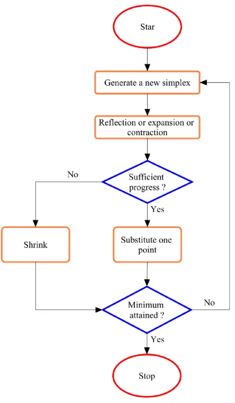
Differential Evolution (DE) is a stochastic optimization method which permits alternative solutions for some of the complex composite design and optimization problems such as increasing frequency and frequency separation and obtaining lightweight design. Differential Evolution algorithm includes the following main stages: initialization, mutation, crossover and selection as shown in Figure 4.1. The optimum results of the algorithm change with the parameters: scaling factor, crossover and population size. Detail description of the DE can be found in Storn and Price (1997). DE always considers a population of solutions instead of a single solution at each iteration and is also computationally expensive. It is relatively robust and efficient in finding global optimum of the objective function. However, it is not guaranteed to find the global optima.