Identification of Dynamics of Movement of the Differential Mobile Robotic Platform
Controlled by Fuzzy Controller
Lukáš VACHO, Martin OLEJÁR, Dušan HRUBÝ, Vladimír CVIKLOVIČ, Jan VALÍČEK, Zuzana PALKOVÁ, Marta HARNIČÁROVÁ, Hakan TOZAN
Abstract: Mobile robots with differential chassis are very often used because of simple construction and a smaller number of drive and sensors elements. For practical
applications, it is necessary to know the kinematic and dynamic structure of the differential mobile robot. This paper deals with identification of the dynamics of the differential robotic platform, using differential kinematics. Electro-optical rpm sensors obtain required values such as speed of the driven wheels. Identification of dynamic system is used to determine the dynamic characteristics of power subsystem of developed EN 20 robot, whose control subsystem is created by single-chip microcontroller. Response of the dynamic system is monitored along with the peripheral velocity of the right and left drive wheels. Incremental encoders that work on optics principle measure the speeds of both wheels. It was necessary to calibrate the sensors and obtain constants for precise speed determination. The monitored system with the dumped oscillation characteristic is approximated by a system with the inertia of the 2nd order. Dynamic system parameters are found. The system approximation is suitable for given evolution of circumferential speeds of the right and left wheels. This is confirmed by the quantitative determination coefficients R2. The equations for calculating peripheral velocities of driving wheels are applied to the system of the differential equations for the differential chassis. A mathematical model of the mobile robot EN20 was obtained for testing control algorithms, where a robot is equipped with sensory systems and it is designed for interior conditions. Fuzzy controller with 49 interference rules is used to control the mobile robot. The real mobile robot path matches the path determined according to simulation model.
Keywords: dynamic system; fuzzy controller; incremental sensor; modelling; mobile robot 1 INTRODUCTION
Mathematical modelling has penetrated into various areas of natural, technical, economic and social sciences and has become an important aid in modelling and simulation of complex systems and in the prediction of different processes [1]. One of the systems that can be modelled is a mobile robot when it is necessary to take into account the kinematics and dynamics of the mobile robot, which allows subsequent planning of the realistic movements of the robot [2]. Realistic mathematical models of mobile robots are obtained through the physics laws that govern their behaviour. In the case of mobile robot navigation where obstacles are considered in the environment, an environment model is created, which is necessary for testing the robot's control and navigation algorithms [3]. For the needs of navigation in mobile robotics, it is necessary to know the mathematical model of the mobile robot for the cases of simulation of control algorithms or of the mobile robotic platform. In the most commonly used types of wheel robots with two [4, 5] with four [6, 7] and more wheels the static and dynamic parameters are monitored, while using the kinematic chassis structures as a basis. Dynamic and kinematic principles are used to create mobile robot models [8, 9]. In the control of non-linear systems, control methods with fuzzy logic are used quite often. The theory of fuzzy sets introduced for the first time by Zadeh, has revolutionized many applications [10]. The theory was practically applied by Mamdani and Takagi-Ssugeno, in the field of control. The role of the fuzzy system transforms the knowledge base into mathematical that have resulted in effective use in many applications [11]. Process of control is directly related to robotics. In robotics it is mainly about the design of controllers designed to control the mobile robot that is to reach the target position and it is required to monitor the robot's declination from the trajectory [12]. Fuzzy logic can be used for the dynamic adaptation of the variables of the
system [13, 14]. In this study, we are trying we are trying to target the potential of recognizing a dynamic system. In our case, the dynamic system is part of the mobile robot, where we focus specifically on speed of the drive wheels. With the evolution of dynamic speed rotation through a dynamic system, identification can determine the behaviour of an actuator subsystem over time. An important role in mobile robotics is to accurately steer a robot to a goal in performing work. For this purpose, in addition to localization algorithms, robustness and reliability of control algorithms are required. PID controllers, as linear system are unusable in nonlinear applications and therefore difficult to apply in the field of mobile robotics when the robot needs to reach the target. For this reason, a combination of PID regulators with fuzzy logic was created. Fuzzy logic is based on grades of membership of an element in a set, where the value of an element in a set is between 0 and 1 compared to the classical edge sets. This method allows the control of non-linear processes, including moving the mobile robot to the target and in our case, fuzzy logic with a fuzzy controller is used to set the motor speed so that the deviation from the desired path of the mobile robot is as small as possible which depends on inputs of the target distance and the angle of rotation. The accuracy and robustness of the proposed fuzzy motor speed controller are given by the number of interference rules [15]. Speed rotation of mobile robots wheel can be sensed in a variety of ways, including the use of incremental encoders [16, 17]. From the measured wheel speeds, it is then possible to derive the peripheral velocity of wheels or, as in our case, the position of the robot by the odometry principle, which is used on the robotic platform EN 20 with a differential platform. The mobile robotic platform is designed to move on solid level surfaces, especially in interior conditions, and is designed to test navigation and control algorithms.
2 MATERIAL AND METHODS
2.1 Kinematic Model of Differential Mobile Robot
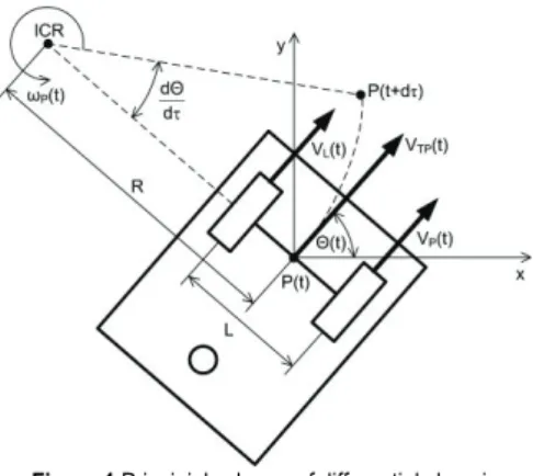
Differential chassis and type of its drive are characterised by the existence of two independently driven wheels, the mutual distance of which L is called gauge. The movement of the chassis based on the differential drive which is illustrated by Fig. 1, can be characterised as a movement along the arcs around the instant centre of rotation (ICR), with the radius R of this arc.
Figure 1 Principial scheme of differential chassis
The instantaneous tangential velocity VTP(t) [18] of the
differential chassis can be calculated as follows:
( ) ( )
TP P
V t =ω t R (1) where: ωP(t) is robot’s angular velocity, s−1; R is turning
radius, m. Peripheral velocities of the left VL(t) and right VP(t) wheel with wheels gauge L can be calculated with the use of the following relations:
( ) ( ) ( ) ( ) ; 2 P( ) L( ) 2 L P P L V t V t L L V t t R R V t V t ω + = − = ⋅ − (2)
By solving the system of the two previous equations we calculate the turning radius R and the robot’s angular velocity ωP(t) as follows: ( ) ( ) ( ) ( ) ( ) ; ( ) ( ) 2 P L P L P P L V t V t V t V t L t R L V t V t ω = − = + ⋅ − (3) By substituting the Eq. (3) to the Eq. (1), we get a relation for calculation of the tangential velocity through the peripheral velocity of the right and left wheels:
( ) ( ) ( ) 2 P L TP V t V t V t = + (4) According to wheel peripheral velocity and chassis construction dimensions, it is possible to obtain equations to determine the position of the robot with differential chassis as the system of differential equations in the Cartesian coordinate system:
[
]
[
]
( ) ( ) ( ) ( 1) ( ) ( ) ( ) cos ( ) ( 1) 2 ( ) ( ) ( ) sin ( ) ( 1) 2 P L P L P L V k V k k T k L V k V k x k k T x k V k V k y k k T y k Θ Θ Θ Θ − = + − + = + − + = + − (5)where: x(k),y(k) is current sample of the xth, yth mobile robot
coordinate, m; x(k−1), y(k−1) is the previous sample of the
xth, yth mobile robot coordinate, m; Θ(k) is current angle of
the robot turning, °; Θ(k−1) is the previous angle of the robot turning, °; VP(k), VL(k) is current sample of the right
and left wheel peripheral velocity, m/s; T is the sampling period, s.
2.2 Kinematic Model of Differential Mobile Robot
For calculating the coordinates of the mobile robot, the motion of a robot, with the differential chassis on the flat plane pad, is used. The calculated current position is referenced precisely to the centre of the rotation axis of the mobile robot (centre of the drive wheel axis). From the distance of both wheels is determined the angle of rotation
Θ of the mobile robot with sP right and sL left wheel:
P L
u
s s
k
Θ= − (6) where: ku is calibration constant for determining the
directional angle of the mobile robot, m/°. We can calculate the path increment value dr by relationship. Advantage of this approach is that the angle Θ is not directly dependent on the previous state. It depends on the measured distance and hence the slipping of the wheels.
( ) ( ) ( 1) ( 1)
2 2
P L P L
s k s k s k s k
dr= + − − + − (7) Actual coordinates of the position of the robot x(k),
y(k) with differential chassis use the value of the path
increment as follows:
[
]
[
]
( ) cos ( ) ( 1) ( ) sin ( ) ( 1) x k k dr x k y k k dr y k Θ Θ = ⋅ + − = ⋅ + − (8) where: x(k−1), y(k−1) previous sample of x and y-axis of the mobile robot, m; Θ(k) current angle of rotation of mobile robot, °.2.3 The Identification of Dynamics of Movement of the Robot
In mobile robots with wheel chassis, devices in most cases include a drive, a gearbox and a driving wheel. This set of devices represents a dynamic system, the behaviour of which must be identified. An experimental method based on the transition characteristic for determination of static and dynamic properties of unknown systems is a commonly used method. If the response of the system is with damped oscillations characteristic, we approximate
the examined system with an inertia of the 2nd order in the
Laplace’s form, where ξ0 is a damping coefficient, 1; T0 is
the time constant of the dynamic system response, s.
2 2 0 0 0 ( ) 2S 1 S K G s T s ξ T s = + + (9) On the basis of the values ai and the time intervals ti,
where N is the number of values read from the transition characteristic, ξ0 and T0 are as follows:
(
)
1 2 0 0 2 2 1 2 2 2 0 0 1 1 ln ln or ln 4 ln 1 i i i i i i i i N a a a a a a a a T t t N ξ ξ π π ξ π + + + + + = − = − + + − = − (10)Figure 2 The block diagram of differential mobile robotic system Based on kinematic relationships and using the principle of identification of dynamic systems and data from identification of dynamic system, the motion of the mobile robot can be described. The block diagram in Fig. 2 shows the arrangement of functional blocks of a mobile robotic device in a closed loop, which can be considered as a dynamic system. The point of interest as a dynamic system, in this case, is the power subsystem of the mobile robot. The motor speed is set by the controller and the time response of peripheral velocity of the mobile robot wheels is monitored at the jump rpm change.
2.4 Experimental Mobile Robot with Differential Chassis
Identification of the robot motion dynamics was performed on the developed mobile robotic platform EN20. The principal scheme of this robot is shown and block diagram of the robot is shown in Fig. 3 [19]. Communication with the drive modules, incremental sensors, power monitor with control module run according to the SPI communication standard in a four-wire connection with a data flow rate of 1 Mbps. The centre of communication between the internal modules and PC is the module IM1.0, which includes the single-chip microcontroller C8051F340 from the Silicon Laboratories. The control module IM1.0 combines the communication standards UART and SPI. UART is a serial line that is exclusively designated for communication with the control computer via the full-duplex protocol XBee. The second
type of communication is SPI, where the module is set as "MASTER" in a 4-wire connection with the possibility of connecting eight SPI "SLAVE" modules. Communication with PC is solved through a virtual serial port via USB (chip CP2102). BLY171S 24V-4000 type [20] (BLDC) motors are used to drive the mobile robot EN 20, which are controlled by the MR1.0R and MR1.0L controllers. Measure velocity of drive wheels of the mobile robot provides optical incremental sensors: TP 6.35 1024 BZ TTL [21] with a resolution of 1024 pulses per revolution.
Figure 3 Scheme and block diagram of differential chassis of EN 20 mobile
robot
2.5 Fuzzy Controller
Of the many available feedback control methods [27], fuzzy is considered an optimal way of controlling nonlinear systems, which is also a mobile robot [26]. It is also possible to use more sophisticated controlling methods when using neural networks. These methods are principally more complex and computationally more demanding [28]. An error of rotation angle has the most significant effect on the overall accuracy of determining the current position. With increasing distance from the starting position, the position determination error for the plane increases linearly. Compensate of error in the motion trajectory is possible with feedback because inputs to control are functions of the actual state of the system and not just the start and end point functions. According to [22, 23] definition of a Fuzzy Set A(FS) like a set function on
universe E, described by the membership function µA(x)
(MF), where first definition is now known as the Type-1 Fuzzy Set:
{
, ( )µ}
= A ∈
A x x x E (11)
A fuzzy system is composed of fuzzifier, rules, inference, and defuzzifier. In our case the fuzzy controller is used to control direction of the mobile robot EN20. Block diagram of fuzzy controller with importance of input fuzzy controller values is illustrated in Fig. 4.
The inputs to the controller are the mobile robot's deflection angle from the target position δ whose range of values is ±90° and the robot distance from the target position D whose range is 0 to 2 m:
2 2
TARGET TARGET
( ) ( )
D= x x− + −y y (12) Where xTARGET,yTARGET is axis of target, m; x, y is axis
coordinate of the mobile robot of reference point, m; y is y-axis coordinate of the mobile robot of reference point, m. Before calculating the mobile robot's deflection angle from the target position, the target point angle must be determined relative to the mobile robot reference point
ΘTARGET and then can be determined the mobile robot's
deflection angle δ. TAEGET TAEGET 180 arcsinyTARGET y D Θ π δ Θ Θ − = ⋅ = − (13)
The result of calculating the position of the mobile robot is determined by the time interval. This interval is given by the transmission rate of the communication standard. In the real model it is 330 ms, and this value is also used in simulations.
Figure 4 Block diagram of the fuzzy controller used to control model of the
mobile robot EN20 and importance of input fuzzy controller values
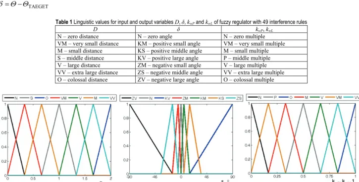
Table 1 Linguistic values for input and output variables D, δ, kwP and kwL of fuzzy regulator with 49 interference rules
D δ kwP, kwL
N – zero distance N – zero angle N – zero multiple VM – very small distance KM – positive small angle VM – very small multiple M – small distance KS – positive middle angle M – small multiple S – middle distance KV – positive large angle P – middle multiple V – large distance ZM – negative small angle V – large multiple VV – extra large distance ZS – negative middle angle VV – extra large multiple O – colossal distance ZV – negative large angle O – colossal multiple
Figure 5 Membership functions of linguistic variables for mobile robot offset from target position δ, multiples of maximum right engine kwP and left kwL. They are identical
with membership functions of linguistic variables for robot distance from target position D. The outputs of the fuzzy controller are multiples of the
maximum speed of the right motor kwP and the left motor kwL, whose range of values is 0 to 1.
max; max
P wP P L wL L
w =k ⋅w w =k ⋅w (14)
where wP, wL are rpm of right and left motor, %; wPmax, wLmax are maximum rpm of right and left motor, %; kwP, kwL
is multiple of maximum rpm of right and left motor in range 0 – 1. The input parameters of the mobile robot positioning algorithm are the target position xTARGET, yTARGET and rpm wPmax, wLmax of the right and left motor in
of the motor, because the motor current protection is active. The decrease of the current is reflected in the change of engine speed and thus in the speed of the drive wheels. The same value is used for simulation as well as for experiments. The target position values xTARGET, yTARGET
are set in the algoritm to: xTARGET = 10 m, yTARGET = 0 m.
The purpose is to achieve a target position by a mobile robot with an accuracy of 10 cm.
After defining linguistic values for input and output variables, their membership functions are also defined as follows in Fig. 5.
3 RESULT AND DISCUSSION
The identification of dynamics of movement of the robot EN20 was determined by sending the rpm values of the left and right drives from the application in the PC, when at the beginning the robot stood still, which is one of the basic conditions for identification. The calibration constants of the right encoder kP = 2317.430279 pulses per
meter and the left encoder kL = 2255.876494 pulses per
meter were determined. Differences between constants are due to inaccuracy of gearbox and inaccuracy of encoder mounting. Steep change of rpm of the right and left drives represented the test jump signal, and the response of the dynamic system was the evolution of the peripheral speed of the right and left driving wheels. This peripheral velocity was measured by encoders which were independently imbedded in the driving wheels axes. Fig. 6 illustrates the evolution of the right and left driving wheels peripheral velocity at a steep change of drive rpm from 0 to 60% of the maximum rpm. It is evident from the peripheral velocities of the driving wheels that drive of the mobile robot EN20 behaves as a dynamic system with damped oscillations characteristic. This system is approximated by a static system with the inertia of the 2nd order according to
the relation 10. Parameters for this type of dynamical system are T0 time constant, ξ0 damping coefficient and KS
amplification, which in our case are calculated as the ratio of the steady peripheral velocity of the driving wheel and the drive rpm.
Figure 6 Evolution of the peripheral speed of the right and left driving
wheel, at a steep change of the drive rpm from 0 to 60% of the maximum rpm Steep change of the drives rpm was limited to 60% of the maximum rpm because at higher rpm the current protection is activated in order to reduce the current supplied to the drives and thus to reduce the drives rpm. On the basis of the values in the measured interval between 2% to 60% of peripheral velocity, we determined the damping coefficients ξ0P, ξ0L (right, left wheel) and the time
constants T0P, T0L (right, left wheel) of the peripheral
velocities evolution of both driving wheels as an arithmetic mean of all the values, as follows:
0 0 0 0 0 3675 0 110833 s 0 3575 0 110833 s P P L L . T . . T . ξ ξ = = = =
The KSP and KSL gains cannot be calculated as the
average of all values due to the significant influence of the given parameters on the values of steady peripheral velocities of the driving wheels and hence on the mobile robot velocity. Therefore, it was necessary to describe through regression the evolution of the KSP and KSL gains
by polynomials. The KSP and KSL gain values at different
drive rpm are shown in Fig. 7.
Figure 7 Values of amplification of the peripheral velocity of the right and
left driving wheel at different drive rpm
The evolution of amplification of the KSP and KSL can
be described by the polynomial of the fourth order in the following form: 9 4 7 3 5 2 9 4 7 3 5 2 3 56 10 6 68 10 4 82 10 0 00167 0 031 4 45 10 8 10 10 5 60 10 0 00184 0 032 SP P P P P SL L L L L K . w . w . w . w . K . w . w . w . w . − − − − − − = × − × + + × − + = × − × + + × − + (15)
By substituting the mean values of ξ0P, ξ0L, T0P, T0L in
the Eq. (6), by replacing the KSP and KSL gain by the
polynomial of the fourth order and with subsequent deducing the dynamic system response during the steep change of rpm of the drives wP and wL we obtain Eqs. (16),
for the calculation of the driving wheel peripheral velocity
VP and VL. 9 5 7 4 5 3 2 3 3158 9 5 7 4 5 3 2 ( ) (3 56 10 6 68 10 4 82 10 0 00167 0 031 ) cos(8 3912 ) 0 3952sin(8 3912 ) 1 ( ) (4 45 10 8 10 10 5 60 10 0 00184 0 032 ) cos(8 4263 ) 0 1 P P P P P P . t L L L L L L V t . w . w . w . w . w . t . . t e V t . w . w . w . w . w . t . − − − − − − = × − × + + × − + × + × − = × − × + + × − + × + × − 3 2256.3828sin(8 4263 )t . t e (16)
We verified the correctness of the calculation by simulation, and the actual and calculated peripheral velocities of the left and right driving wheels at the steep change of the drive rpm from 0 to 60%, that are shown in Fig. 8.
Figure 8 Evolutions of real and calculated peripheral velocities of the right and left driving wheel in experiment
In a measured dynamic system of a mobile robot (power subsystem) there are some construction details, which negatively affect the evolution of peripheral velocity. In case of mobile robot navigation process and control process it can be reflected as the aberrance of real measure value. Equations for calculation of the driving wheels peripheral velocities were subsequently applied to the set of differential equations for a differential chassis (Eq. (5)), by which we obtained the mathematical model of the mobile robot EN20, on which we tested the control algorithms with fuzzy controller of the 49 rules for the kwP
and kwL output variables. Based on these fuzzy sets, it was
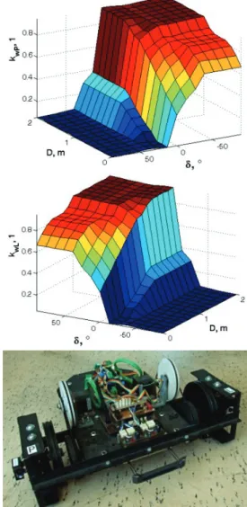
determined that the base Number of rules can be different [24, 25]. Because of the definition of membership function, linguistic values and interference rules, the control surfaces for the multiples of the maximum rpm of right motor kwP
and the left motor kwL are shown in Fig. 9.
The proposed fuzzy controller with nine 49 rules was used to control model of the mobile robot as well as the EN20 robot. The result of the process of the simulation of the mobile robot and the real track of the mobile robot and relative error of peripheral velocity is shown in Fig. 10.
Figure 9 Control surfaces of the fuzzy controller with 49 interference rules for
multiples of maximum rpm: right motor kwP, left motor kwL and the mobile Robot
EN 20 with differential chassis
Figure 10 Process of track of mobile robot EN20, mathematic model of mobile
robot and Relative error of the peripheral velocity of the left driving wheel, and right driving wheel at a steep change of the drives rpm form 0 to 60%
The model of the mobile robot EN20 quite accurately describes the behaviour of the real robot, so it is possible to use this mathematical model to search for and optimize other control algorithms. Inaccuracy in the differences between the real robot and the model are due to the imprecise storage of the gearboxes as well as the uneven terrain. Stabilisation of the system during a simulated calculation of the right wheel occurs at a time of 1.796 s at the value of 0.3640 m/s, where in the real case the dynamic system stabilised at the value of 0.3352 at a time of 1.437 s. We have determined similarly the characteristic form of peripheral velocity and times of stabilisation of the dynamic system when the simulated case the peripheral velocity of the left wheel was stabilised at the value of 0.3519 m/s at a time of 1.372 s. Fig. 14 shows a relative error of the left and right driving wheel peripheral velocity at a time from the start of the system identification till the system stabilisation. The biggest relative error at the change of the right wheel peripheral velocity occurs at a time of 0.130 s when initial oscillation and subsequent time delays of the system take place. The maximum value of the relative error of the left wheel peripheral velocity occurs at a time of 0.098 s where similarly as in the case of the right wheel velocity the system oscillations take place.
4 CONCLUSION
The mobile robotic platform presented in this article EN20 is considered from the viewpoint of a model to be a stochastic, dynamic, continuous, and non-linear model. Mobile robot with a differential chassis has separate drive and measuring wheels, what is advantage in proces of measure rpm. Identification of the robot motion dynamics using the transition characteristic was performed. The response of the dynamic system and therefore of the peripheral velocity of the right and left driving wheels was monitored. The dynamic system with the damped oscillation characteristic was approximated by a static system of the second-order, with time constant, damping coefficient, and gain being determined. Approximation corresponds to the assumption of determination of the system of the second order, which was confirmed based on determination coefficients, where the value R2 = 0.9080
was for the evolution of the right wheel rpm and the value
R2 = 0.9303 was for the evolution of the left wheel rpm.
The amplifications have a significant effect on the values of stabilised peripheral velocities. For this reason, regression analysis was used for describing the evolution of amplification by polynomials of the fourth order. The mathematical model of the robot EN20 was obtained by deducting the relations for calculation of the driving wheels peripheral velocity and their application in the differential equations of the mobile robot differential chassis. We deduce in conclusion that by using dynamic system identification and kinematic equations for a differential robotic platform, it is possible to obtain a model for a mobile robot presented in this study. Such a procedure could also be applied to other kinematic structures of robots. It is possible to use such model for testing the control algorithms based on the soft-computing methods, including fuzzy logic [13, 25]. In this case, a regulator with 49 interference rules and triangular membership functions was used, and the motor speeds of the mobile robot EN 20
have been determined. In a fairly accurate manner, the speed was determined by the regulator when the input values were the mobile robot rotation values and the mobile robot's offset angle from the target position. This principle can be used in mobile robotic navigation process [26], what was in this case. The solution gives the incentive to further research into control algorithms for mobile robot control and implementing complex control algorithms into microcontrollers to reach the target position by a robot in the shortest possible time with the maximum precision.
Acknowledgements
The study was supported by the VEGA, The Ministry of Education, Science, Research and Sport of the Slovak Republic under grant reference number: 1/0720/18.
5 REFERENCES
[1] Barnes, B. & Fullford, G. (2015). Mathematical Modeling with Case Studies. Cambridge, USA: CRC Press.
[2] Wang, T., Wu, Y., Liang, J., Han, C., Chen, J., & Zhao, Q. (2015). Analysis and Experimental Kinematics of a Skid-Steering Wheeled Robot Based on a Laser Scanner Sensor. Sensors, 15(5), 9681-9702.
https://doi.org/10.3390/s150509681
[3] Joshi, M. M. & Zaveri, M. A. (2010). Neuro-fuzzy based autonomous mobile robot navigation system. In 11th International Conference on Control Automation Robotics & Vision. https://doi.org/10.1109/ICARCV.2010.5707354
[4] Mu, B., Chen, J., Shi, Y., & Chang, Y. (2017). Design and Implementation of Nonuniform Sampling Cooperative Control on a Group of Two-Wheeled Mobile Robots. In IEEE Transactions on Industrial Electronics.
https://doi.org/10.1109/TIE.2016.2638398
[5] Ma, Y., Cocquempot, V., Najjar, M., & Jiang, B. (2016)., Multiple-model based actuator fault compensation for two linked 2WD mobile robots. In 3rd Conference on Control and Fault-Tolerant Systems (SysTol).
https://doi.org/10.1109/SYSTOL.2016.7739725
[6] Terada, K., Miura, H., Okugawa, M., & Kobayashi, Y. (2016). Adaptive speed control of wheeled mobile robot on uncertain road condition. Journal of Robotics and Mechatronics, 26(5), 687-694.
https://doi.org/10.20965/jrm.2016.p0687
[7] Bascetta, L., Baur, M., & Gruosso, G. (2017). 'ROBI': A Prototype Mobile Manipulator for Agricultural Applications. Electronics, 6(2), pp. 39.
https://doi.org/10.3390/electronics6020039
[8] Abhishek, V. & Saha, S. K. (2016). Dynamic identification and model based control of an Omni-wheeled mobile robot. In 4th RSI International Conference on Robotics and Mechatronics. https://doi.org/10.1109/ICRoM.2016.7886810 [9] Wang, C., Liu, X., Yang, X., Hu, F., Jiang, A., & Yang, C.
(2018). Trajectory Tracking of an Omni-Directional Wheeled Mobile Robot Using a Model Predictive Control Strategy. Applied. Science, 8(2), pp. 231.
https://doi.org/10.3390/app8020231
[10] Zadeh, L. A. (2002). From Computing with Numbers to Computing with Words: From Manipulation of Measurements to Manipulation of Perceptions. In The Dynamics of Judicial Proof, Physica.
https://doi.org/10.1007/978-3-7908-1792-8_5
[11] Castillo, O. (2012). Interval Type-2 Mamdani Fuzzy Systems for Intelligent Control, Berlin, Heidelberg, Springer. https://doi.org/10.1007/978-3-642-24666-1_12
[12] Alouache, A. & Wu, Q. (2018). Fuzzy logic PD controller for trajectory tracking of an autonomous differential drive
mobile robot (i.e. Quanser Qbot). Industrial Robot: the international journal of robotics research and application, 45(1), 23-33. https://doi.org/10.1108/IR-07-2017-0128
[13] Caraveo, C., Valdez, F., & Castillo, O. (2017). A New Meta-Heuristics of Optimization with Dynamic Adaptation of Parameters Using Type-2 Fuzzy Logic for Trajectory Control of a Mobile Robot. Algorithms, 10(3), pp. 85. https://doi.org/10.3390/a10030085
[14] Castillo, O., Amador-Angulo, L., Castro, J. R., & Garcia-Valdez, M. (2016). A comparative study of type-1 fuzzy logic systems, interval type-2 fuzzy logic systems and generalized type-2 fuzzy logic systems in control problems. Information Science, vol. 354, 257-274.
https://doi.org/10.1016/j.ins.2016.03.026
[15] Abdalla, M. O. (2018). Optimal Fuzzy Controller: Rule Base Optimizer Generation. Journal of Control Engineering and Applied Informatics, 20(2), 76-86.
[16] Klancar, G., Zdesar, A., Blazic, S., & Skrjanc, I. (2017). Wheeled Mobile Robotics. USA: Elsevier.
[17] Wang, G., Ding, Y., Hou, Y., Zhou, Y., & Jia, X. (2018). Two-Level Fault Detection and Isolation Algorithm for Vehicle Platoon. In IEEE Access, vol. 6, 15106-15116. https://doi.org/10.1109/ACCESS.2018.2815644
[18] Dhaouadi, R. & Hatab, A. A. (2013). Dynamic Modelling of Differential-Drive Mobile Robots using Lagrange and Newton-Euler Methodologies: A Unified Framework. Advances in Robotics & Autamtion, 2(2), pp. 107.
[19] Cviklovič, V., Olejár, M., Hrubý, D., & Lukáč, O. (2013). Odometry in Navigation of Autonomous Mobile Robots, Slovakia: SUA Nitra: Slovakia.
[20] Technical description of BLDC motor - Anaheim Automation. www.anaheimautomation.com
[21] Technical description of optical encoder. www.usdigital.com
[22] Robles, E. O., Melin, P., & Castillo, O. (2018). Comparative analysis of noise robustness of type 2 fuzzy logic controllers. Kybernetika, 54(1), 175-201.
https://doi.org/10.14736/kyb-2018-1-0175
[23] Mendel, J. M. (2017). Uncertain Rule-Based Fuzzy Systems, USA: Springer International Publishing AG.
https://doi.org/10.1007/978-3-319-51370-6
[24] Almasri, M., Elleithy K., & Alajlan, A. (2015). Sensor Fusion Based Model for Collision Free Mobile Robot Navigation. Sensors, 16(1), pp. 24.
https://doi.org/10.3390/s16010024
[25] Omrane, H., Masmoudi, M. S., & Masmoudi, M. (2016). Fuzzy Logic Based Control for Autonomous Mobile Robot Navigation. Computational Intelligence and Neuroscience, pp. 10. https://doi.org/10.1155/2016/9548482
[26] Oltean, S. E., Dulău, M., & Puskas, R. (2010). Position control of Robotino mobile robot using fuzzy logic. In IEEE International Conference on Automation, Quality and Testing, Robotics (AQTR).
https://doi.org/10.1109/AQTR.2010.5520855 Contact information:
Lukáš VACHO, M. Eng.
(Corresponding author)
Department of Electrical Engineering, Automation and Informatics, Faculty of Engineering,
Slovak University of Agriculture in Nitra, Tr. A. Hlinku 2 949 01 Nitra. [email protected]
Martin OLEJÁR, Associate Professor, PhD, M. Eng.
Department of Electrical Engineering, Automation and Informatics, Faculty of Engineering, Slovak University of Agriculture in Nitra, Tr. A. Hlinku 2 949 01 Nitra, Slovak Republic
Dušan HRUBÝ, Professor, PhD, M. Eng.
Department of Electrical Engineering, Automation and Informatics, Faculty of Engineering, Slovak University of Agriculture in Nitra, Tr. A. Hlinku 2 949 01 Nitra, Slovak Republic
Vladimír CVIKLOVIČ, Associate Professor, PhD, M. Eng.
Department of Electrical Engineering, Automation and Informatics, Faculty of Engineering, Slovak University of Agriculture in Nitra, Tr. A. Hlinku 2 949 01 Nitra, Slovak Republic
Zuzana PALKOVÁ, Professor, PhD, M. Eng.
Department of Electrical Engineering, Automation and Informatics, Faculty of Engineering, Slovak University of Agriculture in Nitra, Tr. A. Hlinku 2 949 01 Nitra, Slovak Republic
Department of Mechanical Engineering, Faculty of Technology, Institute of Technology and Business in České Budějovice,
Okružní 10, 370 01 České Budějovice, Czech Republic [email protected]
Jan VALÍČEK, Associate Professor, PhD, M. Eng.
Department of Electrical Engineering, Automation and Informatics, Faculty of Engineering, Slovak University of Agriculture in Nitra, Tr. A. Hlinku 2 949 01 Nitra, Slovak Republic
Department of Mechanical Engineering, Faculty of Technology, Institute of Technology and Business in České Budějovice,
Okružní 10, 370 01 České Budějovice, Czech Republic [email protected]
Marta HARNIČÁROVÁ, PhD, M. Eng.
Department of Electrical Engineering, Automation and Informatics, Faculty of Engineering, Slovak University of Agriculture in Nitra, Tr. A. Hlinku 2 949 01 Nitra, Slovak Republic
Department of Mechanical Engineering, Faculty of Technology, Institute of Technology and Business in České Budějovice,
Okružní 10, 370 01 České Budějovice, Czech Republic [email protected]
Hakan TOZAN, Associate Professor, PhD
School of Engineering and Natural Sciences, Istanbul Medipol University, Istanbul, 34810, Turkey [email protected]