©BEYKENT UNIVERSITY
DIODES LOADED ACTIVE MICROSTRIP ANTENNAS DESIGN AND ANALYSIS OF DIODES EFFECTS ON
ACTIVE ANTENNAS FOR RF WIRELESS RECEIVER-TRANSMITTER SYSTEMS
Ender KARAZEYBEK1, Adnan KAYA2
1 2 [email protected], [email protected] Department of Electronics and Communication
Engineering Süleyman Demirel University Isparta, Turkey, 32260
ABSTRACT
This paper is presentation of designed different diodes loaded active model dissimilar geometries of micro strip patch antennas. As known, mikrostrip patch antennas have complex impedance and its impedance changes with frequency. Because of this, imaginer part of micro strip patch antennas is minimized by effect of diodes having capacitive reactance thus maximum power radiating is occurred. The aim of this project is to present different diodes loaded patch antenna for ISM 2.4 Ghz and to indicate active antenna performance according to influence of locations and dc biasing of diodes then to compare the antenna parameters of passive models. Besides, this project is used three types of diodes which are schottky Barrier diodes, silicon variable capacitance diode and tuner diode and four diodes whose are bas70, bas83, bb619 and bb721. The simulation programmer is AWR Design Environment Microwave Office 2007 (MWO) whose analysis meted is moment (Mom). Finally, the antennas that are projected are ready condition for LAN application or wireless RF receiver-transmitter systems.
Return loss of designed antennas are between -25.54 dB and -36.17 dB. Gain does not change a lot but results of VSWR and Input impedance is satisfactory when comparing the passive model's results.
Keywords: Active antenna, diode, Micro strip, 2.4 GHz ISM
ÖZET
Bu makalede farklı diyotlar ve geometriler ile entegre edilmiş aktif model mikroşerit yama anten tasarımı ve pasif modelleri ile karşılaştırılması gösterilmiştir. Mikroşerit Yama Antenlerin sahip oldukları empedans değeri bilindiği gibi komplekstir ve frekansla değişmektedir. Bu nedenle aktif bir eleman olan diyot kullanarak kapasitif
üzerinde birebir etki ederek maksimum güç iletimi sağlanması ve anten parametrelerinin sonuçlar üzerindeki etkisinin incelenmesi amaçlanmıştır. Tasarlanan Antenlerin tamamı 2,4 Ghz ISM bandı üzerinde çalışmaktadır. Schottky bariyer diyot, Değişken kapasiteli diyot ve ayarlanabilir diyot tipinde 3 farklı tip diyot kullanılmış ve bunların ters gerilim-kapasite eğrisi referans alınmıştır. Kullanılan diyot sayısı 4 olup bunlar sırasıyla bas70, bas83, bb619, bb721 ile isimlendirilen yüzey montajlı diyotlardır. farklı diyotlar ve farklı mikroşerit yama modelleri kullanarak moment metodu vasıtasıyla AWR Design Environment Microwave Office 2007 (MWO) simülasyon programı yardımıyla analiz edilmiş ve LAN uygulamaları yada kablosuz alıcı verici sitemler için hazır devreler meydana getirilmiştir.
Tasarlanan Antenlerin geri dönüş kaybı -25.54 dB ile -36.17 dB arasında değişmekte olup, pasif antenler ile karşılaştırıldığında kazancı çok değişmemekte olmasına rağmen VSWR ve giriş empedansı pasif modele göre tatminkâr seviyede sonuçlar vermiştir.
Anahtar Kelimeler: Aktif anten, Diyot, Mikroşerit, 2,4 GHz ISM bandı
1. INTRODUCTION
Microstrip antennas have several advantages, including that they are lightweight and small-volume and that they can be made conformal to the host surface. In addition, Microstrip antennas are manufactured using printed-circuit technology, so that mass production can be achieved at a low cost [1].
Microstrip antenna is one of the important elements in the RF system for receiving or transmitting the radio wave signals from into the air or any medium in addition to active antenna has active device or devices and are employed in the passive antenna elements to improve antenna performance, the terminology of "active integrated antenna" indicates more specifically that the passive antenna elements and the active circuitry are integrated on the same substrate [2]. In conventional wireless or radar systems the antenna and circuit have been considered as separate subsystems. This has led to developments of partial systems by two communities, each of which was expert in the design of its own technology but which in general knew little about the complexities of the other area [3].
Antennas For Rf Wireless Receiver-Transmitter Systems
Microstrip active integrated antennas are easy integration with microwave integrated circuit. Integration with microwave device can be realised because of the structure of the microstrip is also similar to a circuit board and the easiness to create a matching network for any microwave devices [10].
Active integrated antennas can be classified according to active elements functions which are integrated in to the surface. The principal functions of this element in active antennas to produce RF signals, RF signals is to strengthen or frequency conversion. In this paper, frequency conversation type models are chosen.
2. ANTENNA DESIGN AND EQUIVALET CIRCUIT OF ACTIVE DEVICE
Antenna dimensions are determined at desired operational frequency. Antenna impedance is matched the device impedance. In this project, matching circuit is used for necessary. Dc bias circuit that is well isolated from the radio frequency circuit so, low impedance X/4 open stub microstrip line is used.
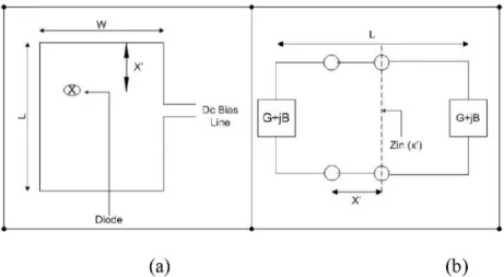
Varaktor diodes may be used to tune the operating frequency of microstrip patch antennas. When a varaktor diode is integrated with a radiating patch, it provides a variable capacitive reactance at the point of its location, thereby changing the resonance frequency of the patch. Figure 2 is shown that schematic diagram of active antenna model and equivalent transmission line model. Diode's location is most significant for input impedance.
Z,„
(x)
=2G
cos2(fix ) + — — — sinG2 + B2 . ,. B 2 (fix ) -Bsin(2fix )Y2 y
y0 y0
where f is the propagation constant of the microstrip line, Yo is the characteristic admittance of the microstrip line, G and B is the total antenna conductance and the radiating edge susceptance, respectively. Equation (1) can be further simplified for practical case of G/Yo << 1 and B/Yo <<1 to equation (2) [5].
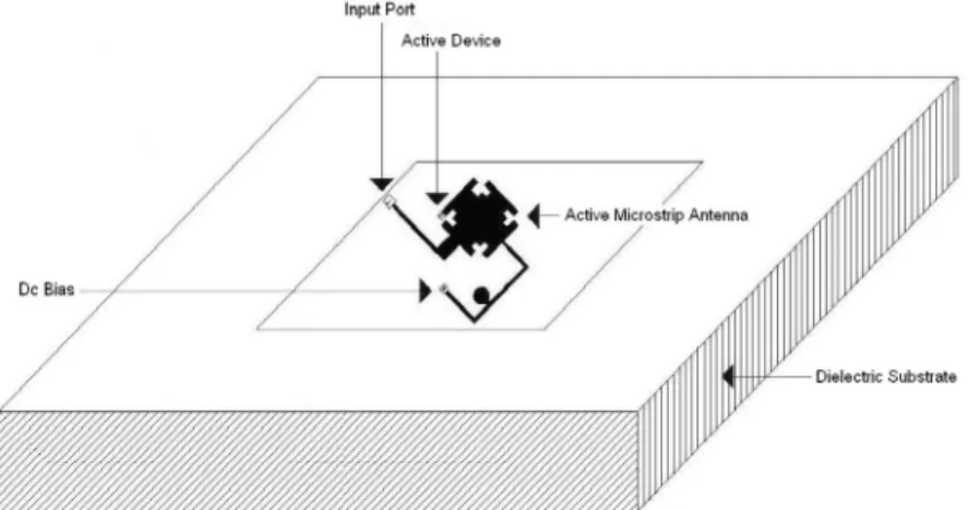
Input Port Active Device
Figure 1. Active microstrip patch antenna
= c o s ^ (2)
„( ' 2G
Equivalent circuit characterization of the active device is of crucial importance to active antenna simulation. Full performance prediction can only be achieved using both linear and nonlinear device characterization. In particular for oscillator analysis, where accurate frequency and power level are required, for amplifier linearity analysis, and for mixer or frequency conversion action, nonlinear models are required [3].
Antennas For Rf Wireless Receiver-Transmitter Systems
The radiation efficiency decreases depending on the geometry. Commonly utilized reactively loaded impedance matching method is a successful technique since the impedance variations are the dominant bandwidth limiting factor [8].
(a) (b)
Figure 2. (a) Schematic diagram of active antenna, (b) Equivalent transmission
line model.
3. SIMULATION
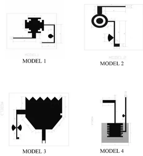
Active element is used to examine the effect of 4 different types of diodes. C-V curve of diodes are taken reference. 4 different models are designed. The reason that is devised 4 different geometric shapes is to see different results in each. Effect of performance parameters of antenna change on different geometric shapes because of the fact that passive antenna is threshold for active antenna. The more passive antenna is successful, the more active antenna is effective and gainful. In addition, performance of active antenna is low when active device location is not suitable. For this reason, diodes locations are placed to edge of antenna when it is compared to a passive model, both different diodes on the same model generate different results and the same diode displays different results on the different models. Accordingly, influence of capacity diode is most important. Thereby increasing the performance of the system is aimed using active device on microstrip antenna for transmitter and receiver for wireless communication systems.
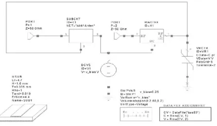
Figure 4. Active antenna schematic diagrams in AWR design environment
Antennas For Rf Wireless Receiver-Transmitter Systems
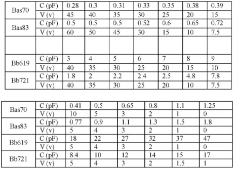
Table 1 shows the capacity for response to voltage of diodes which are bas70, bas83, bb619 and bb721. These characteristics are affected antenna performances which are return loos, input impedance, bandwidth and SWR in simulation results. Also the location of diode is influenced radiation pattern of antenna.
3.1. Simulation Result
Active and passive antennas are designed individually in 4 different diodes. Active antenna position on the x and y axes are placed on the most appropriate point that has been identified. sr =
4.7 h = 1.6mm and an existing tand = 0.019 as substrate (FR4) were used. Schematic representation of the circuit in Figure 7 is shown. The most important parameters in the performance of the model results at the same time according to the comparative analysis of passive antenna have been specified in the table.
Table 1 The capacity for response to voltage of diodes
Bas70 C (pF) 0.28 0.3 0.31 0.33 0.35 0.38 0.39 Bas70 V (v) 45 40 35 30 25 20 15 Bas83 C (pF) 0.5 0.5 0.5 0.52 0.6 0.65 0.72 Bas83 V (v) 60 50 45 30 15 10 7.5 Bb619 C (pF) 3 4 5 6 7 8 9 Bb619 V (v) 40 35 30 25 20 15 10 Bb721 C (pF) 1.8 2 2.2 2.4 2.5 4.8 7.8 Bb721 V (v) 40 35 30 25 20 10 7.5 Bas70 C (pF) 0.41 0.5 0.65 0.8 1.1 1.25 Bas70 V (v) 10 5 3 2 1 0 Bas83 C (pF) 0.77 0.9 1.1 1.3 1.5 1.8 Bas83 V (v) 5 4 3 2 1 0 Bb619 C (pF) 18 22 27 32 37 47 Bb619 V (v) 5 4 3 2 1 0 Bb721 C (pF) 8.4 10 12 14 15 17 Bb721 V (v) 5 4 3 2 1.5 1
MODEL 3 MODEL 4
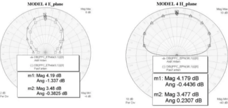
Figure 6. E and H planes of Active antennas in simulation programme
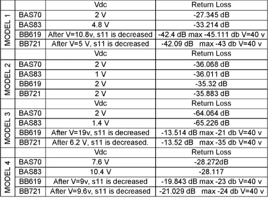
E and H planes of antennas change obviously owing to diodes location. Table 3 is shown that return loss of diodes is depending of dc supply voltage. After exceeding a certain voltage, Return loss of Bb619 and bb721 is decreased. So, the supply voltage is very considerable for antenna efficiency and radiation.
4. COMPARISON OF THE RESULTS
There are some classical techniques for the increasing the matching level and radiation pattern in according to feed point of the antenna [6]. For matching, low impedance X/4 open stub microstrip line is used in all antennas models.
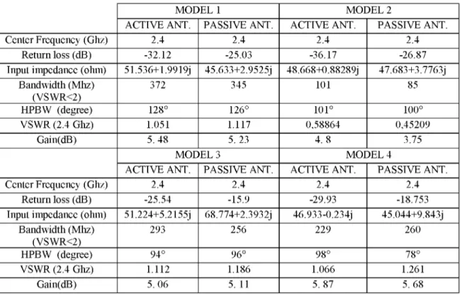
It is obvious that successful results are acquired in model 4 that is made to analyze some of the parameters rather than passive antenna. But all the studies done on the 4 model shows us that all parameters cannot be expected to give excellent results even if very successful over a parameter on another parameter that is desired success. Model 1, 2 and 3 are very satisfactory to passive models.
Table 2. Simulation result of 4 models of active antennas
MODEL 1 MODEL 2
ACTIVE ANT. PASSIVE ANT. ACTIVE ANT. PASSIVE ANT.
Center Frequency (Ghz) 2.4 2.4 2.4 2.4
Return loss (dB) -32.12 -25.03 -36.17 -26.87
Input impedance (ohm) 51.536+1.9919j 45.633+2.9525j 48.668+0.88289j 47.683+3.7763j Bandwidth (Mhz) (VSWR<2) 372 345 101 85 HPBW (degree) 128° 126° 101° 100° VSWR (2.4 Ghz) 1.051 1.117 0,58864 0,45209 Gain(dB) 5. 48 5. 23 4. 8 3.75 MODEL 3 MODEL 4
ACTIVE ANT. PASSIVE ANT. ACTIVE ANT. PASSIVE ANT.
Center Frequency (Ghz) 2.4 2.4 2.4 2.4
Return loss (dB) -25.54 -15.9 -29.93 -18.753
Input impedance (ohm) 51.224+5.2155j 68.774+2.3932j 46.933-0.234j 45.044+9.843j Bandwidth (Mhz) (VSWR<2) 293 256 229 260 HPBW (degree) 94° 96° 98° 78° VSWR (2.4 Ghz) 1.112 1.186 1.066 1.261 Gain(dB) 5. 06 5. 11 5. 87 5. 68
Table 3. return loss of diodes is depending of dc supply voltage
Vdc Return Loss
- BAS70 2 V -27.345 dB
LU BAS83 4.8 V -33.214 dB
U
O BB619 After V=10.8v, s11 is decreased -42.4 dB max -45.111 db V=40 v ^ BB721 After V=5 V, s11 is decreased -42.09 dB max -43 db V=40 v
Vdc Return Loss CN BAS70 2 V -36.068 dB ^ LU BAS83 1 V -36.011 dB U O BB619 2 V -35.32 dB ^ BB721 2 V -35.883 dB Vdc Return Loss CO BAS70 2 V -64.064 dB ^ LU BAS83 1.4 V -65.226 dB U
O BB619 After V=19v, s11 is decreased -13.514 dB max -21 db V=40 v
^ BB721 After 6.2 V, s11 is decreased. -13.52 dB max -35 db V=40 v
Vdc Return Loss
•t BAS70 7.6 V -28.272dB
^
LU BAS83 10.4 V -28.117
U
O BB619 After V=9v, s11 is decreased -19.843 dB max -23 db V=40 v ^ BB721 After V=9.6v, s11 is decreased -21.029 dB max -24 db V=40 v
Antennas For Rf Wireless Receiver-Transmitter Systems
If effects of diodes are considered as a reference, the best performance of return loss is seen model 3 although radiation performance of model 4 is more successful than model 3 species. This model, as well as radiation affects on the model 2 show clearly.
5.CONCLUSION
This Project is made which will be run in 2.4 GHz and it is seen that maximum capacity of the diodes C-V curve ranges should be between 0-5 pF. Otherwise DC supply voltage increases for resonance moreover warming of on the diode may cause negative effects radiation pattern. Diodes also have not been change the polarization of the antenna. Each model has also resonated for 2.4 GHz for passive antennas. Diode attached on the antenna is increased the fundamental parameters of antenna such as RL, Zin, Gain, VSWR.
ACKNOWLEDGMENT
This work was supported by TUBITAK, Career Programme, TUBITAK-107E200 project conducted by Research Center at SDU.
REFERENCES
[1] Girish KumarK. P. Ray, Broadband Microstrip Antennas, Artech House, 2003
[2] Tenshan Lin, Tatsuo Itoh "Active Integrated Antenna," IEEE Microwave Theory and Tec., Vol. 42, pp. 2186-2194, Dec. 1994 [3] K.C. Gupta, Peter S. Hall, Analysis and Design of Integrated Circuit-Antenna Modules, John Wiley&Wiley, 2000
[4] Constantine A. Balanis, Modern Antenna Handbook, John Wiley&Wiley, 2008.
[5] Ramesh Garg, Prakish Bhartic, Microstrip Antenna Design Handbook, 2000.
[6] M.K.A Rahim, Z.W Low, P.J.Soh, A.Askorin, M.H Jamaluddin, M.R. Ahmad (2006) Active and Passive Aperture Coupled Microstrip Antenna Design. International Symposium on Antennas and Propagation 2006
[7] Garg, R., P. Bahartia, and A. Ittipiboon, Microstrip Antenna Design Handbook, Artech House, Boston, London, 2001.
[8] Eric Marzolf, M'hamed Drissi, Global design of an active integrated antenna for milimeter wave
[9] Kai Fong lee and Wei Chan, Advanced in Microstrip printed Antennas, John Wiley&Sons, 1997
[10] Dr. Mohamad Kamal A. Rahim, Azhari Bin Askorin, Mohd Haizal Bin Jamaludin, Mohd Nazri Bin A Karin, Design and Development of Active Integrated Antenna for Wireless Lan Application, 2007
[11] Kin-Lu Wong, Compact and Broadband Microstrip Antennas, John Wiley&Wiley, 2002