Focusing of electromagnetic waves by a
left-handed metamaterial flat lens
Koray Aydin and Irfan Bulu
Department of Physics, Bilkent University, Bilkent, 06800, Ankara Turkey
[email protected] Ekmel Ozbay
Nanotechnology Research Center and Department of Physics, Bilkent University, Bilkent, 06800, Ankara Turkey
Abstract: We present here the experimental results from research conducted
on negative refraction and focusing by a two-dimensional (2D) left-handed metamaterial (LHM) slab. By measuring the refracted electromagnetic (EM) waves from a LHM slab, we find an effective refractive index of -1.86. A 2D scanning transmission measurement technique is used to measure the intensity distribution of the EM waves that radiate from the point source. The flat lens behavior of a 2D LHM slab is demonstrated for two different point source distances of ds = 0.5λ and λ. The full widths at half maximum of the
focused beams are 0.36λ and 0.4λ, respectively, which are both below the diffraction limit.
©2005 Optical Society of America
OCIS codes: (110.2990) Image formation theory; (120.5710) Refraction; (220.3630) Lenses
References and links
1. V. G. Veselago, “The electrodynamics of substances with simultaneously negative values of permittivity
and permeability,” Sov. Phys. Usp. 10, 504 (1968).
2. J. B. Pendry, A. J. Holden, D. J. Robbins, and W. J. Stewart, “Low frequency plasmons in thin-wire
structures,” J. Phys.: Condens. Matter 10, 4785 (1998).
3. J. B. Pendry, A. J. Holden, D. J. Robbins, and W. J. Stewart, “Magnetism from conductors and enhanced
nonlinear phenomena,” IEEE Trans. Microwave Theory Tech. 47, 2075 (1999).
4. D. R. Smith, W. J. Padilla, D. C. Vier, S. C. Nemat-Nasser, and S. Schultz, “Composite medium with
simultaneously negative permeability and permittivity,” Phys. Rev. Lett. 84, 4184 (2000).
5. R. A. Shelby, D. R. Smith, S. C. Nemat-Nasser, and S. Schultz, “Microwave transmission through a
two-dimensional, isotropic, left-handed metamaterial,” Appl. Phys. Lett. 78, 489 (2001).
6. R. A. Shelby, D. R. Smith, and S. Schultz, “Experimental verification of a negative index of refraction,”
Science 292, 77 (2001).
7. C. G. Parazzoli, R. B. Greegor, K. Li, B. E. Koltenbah, and M. Tanielian, “Experimental Verification and
Simulation of Negative Index of Refraction Using Snell’s Law,” Phys. Rev. Lett. 90, 107401 (2003).
8. A. A. Houck, J. B. Brock, and I. L. Chuang, “Experimental Observations of a Left-Handed Material That
Obeys Snell's Law,” Phys. Rev. Lett. 90, 137401 (2003).
9. K. Aydin, K. Guven, C. M. Soukoulis, and E. Ozbay, “Observation of negative refraction and negative
phase velocity in left-handed metamaterials,” Appl. Phys. Lett. 86, 124102 (2005).
10. K. Aydin, and E. Ozbay, “Negative refraction through impedance matched left-handed metamaterial slab,”
J. Opt. Soc. Am. B, (to be published).
11. K. Aydin, K. Guven, M. Kafesaki, L. Zhang, C. M. Soukoulis, and E. Ozbay, “Experimental observation
of true left-handed transmission peak in metamaterials,” Opt. Lett. 29, 2623 (2004).
12. M. Notomi, “Theory of light propagation in strongly modulated photonic crystals: Refraction like behavior
in the vicinity of the photonic band gap,” Phys. Rev. B 62, 10696 (2000).
13. C. Luo, S. G. Johnson, J. D. Joannopoulos, and J. B. Pendry, “All-angle negative refraction without
negative effective index” Phys. Rev. B 65, 201104(R) (2002).
14. E. Cubukcu, K. Aydin, E. Ozbay, S. Foteinopoulou, and C. M. Soukoulis, “Electromagnetic waves:
Negative refraction by photonic crystals,” Nature 423, 604 (2003).
15. E. Cubukcu, K. Aydin, S. Foteinopolou, C. M. Soukoulis, and E. Ozbay, “Subwavelength resolution in a
two-dimensional photonic crystal based superlens,” Phys. Rev. Lett. 91, 207401 (2003).
16. P. V. Parimi, W. T. Lu, P. Vodo, and S. Sridhar, “Imaging by flat lens using negative refraction,” Nature
17. K. Guven, K. Aydin, K. B. Alici, C. M. Soukoulis, and E. Ozbay, “Spectral negative refraction and focusing analysis of a two-dimensional left-handed photonic crystal lens,” Phys. Rev. B 70, 205125 (2004).
18. J. B. Pendry, “Negative Refraction Makes a Perfect Lens,” Phys. Rev. Lett. 85, 3966 (2000).
19. A. Grbic, and G. V. Eleftheriades, “Overcoming the Diffraction Limit with a Planar Left-Handed
Transmission-Line Lens,” Phys. Rev. Lett. 92, 117403 (2004).
20. N. Fang, and X. Zhang, “Imaging properties of a metamaterial superlens” Appl. Phys. Lett. 82, 161
(2003).
21. D. R. Smith, D. Schurig, M. Rosenbluth, S. Schultz, S. A. Ramakrishna, and J. B. Pendry, “Limitations on
subdiffraction imaging with a negative refractive index slab,” Appl. Phys. Lett. 82, 1506 (2003)
22. A. N. Lagarkov, and V. N. Kissel, “Near-Perfect Imaging in a Focusing System Based on a
Left-Handed-Material Plate,” Phys. Rev. Lett. 92, 077401-1 (2004).
23. C. Luo, S. G. Johnson, J. D. Joannopoulos, and J. B. Pendry, “Subwavelength imaging in photonic
crystals” Phys. Rev. B 68, 045115 (2003).
24. N. Fang, H. Lee, C. Sun, and X. Zhang, “Sub-diffraction Limited Optical Imaging with a Silver
Superlens,” Science 308, 534 (2005).
25. J. D. Wilson, and Z. D. Schwartz, “Multifocal flat lens with left-handed metamaterial,” Appl. Phys. Lett.
86, 02113 (2005).
26. C. G. Parazzoli, R. B. Greegor, J. A. Nielsen, M. A. Thompson, K. Li, A. M. Vetter, D. C. Vier, and M.
H. Tanielian, “Performance of negative index of refraction lens,” Appl. Phys. Lett. 84, 3232 (2004).
27. P. Vodo, P. V. Parimi, W. T. Lu, and S. Sridhar, “Focusing by plano-concave lens using negative
refraction,” Appl. Phys. Lett. 86, 201108 (2005).
28. W. T. Lu, and S. Sridhar, “Flat lens without optical axis: Theory of Imaging,”
arXiv:cond-mat/0501715, (2005).
1. Introduction
Materials that possess a negative index of refraction have become a remarkable research area in recent years due their interesting properties and novel applications [1]. One approach taken is to construct a composite metamaterial (CMM) consisting of two components that have permittivity of ε(ω) < 0 [2] and permeability of μ(ω) < 0 [3] simultaneously over a certain frequency range, so that the resulting index of the refraction of the effective medium becomes
0
eff=
εμ
<n [4-11]. Another path was revealed by photonic crystals (PCs), where the band structure led to negative dispersion for electromagnetic (EM) waves. Hence, a negative index of refraction can be associated with the unusual optical properties of PCs [12-17].
In the pioneering work of Pendry et al. [2], a metallic thin wire grid has been shown to exhibit a plasma frequency in the microwave regime, below which the effective permittivity is negative. Thereafter, a split-ring resonator (SRR) structure is proposed to have μ (ω) < 0 near the magnetic resonance frequency [3]. The first experimental demonstration of left-handed metamaterials (LHM) were achieved by arranging ε(ω) < 0 media and μ(ω) < 0 media periodically [4,5]. Experimental verification of negative refraction was reported shortly after [6-9], supporting the existence of neff < 0 medium.
A negative refractive index allows a flat lens to bring EM waves into focus, whereas positive refractive index materials always require curved surfaces to focus EM waves [1,18]. One interesting physical behavior of negative index materials is that they can restore the amplitude of evanescent waves and therefore enable subwavelength focusing [18]. Subwavelength resolution was experimentally verified for negative index materials made of PCs [15] and left-handed transmission-line lenses [19]. Imaging properties of LHMs [20], limitations on subwavelength imaging [21,22] and subwavelength imaging in photonic crystals [23] are investigated theoretically. Recently, a sub-diffraction-limited silver superlens is reported to have operated at optical frequencies [24]. LHM multi-focal flat lenses [25], planoconcave lenses of LHMs [26] and PCs [27] are recent studies making use of the negative refraction concept for constructing an image.
In this paper, we present our recent results from research conducted on negative refraction and the flat lens behavior of LHMs. Our structure exhibits high transmission [9] and low reflection [10] at a certain frequency. First, the negative index of refraction for the two-dimensional (2D) LHM is verified by using the Gaussian beam shifting method. An
omni-directional source is then placed at two different distances away from the LHM lens, in which a clear image of the source is subsequently observed. The measured full widths at half maximum (FWHM) of the focused beams are 0.36λ and 0.4 λ for two different source distances. This is consistent with the result that negative index materials can focus EM waves onto an area smaller than a wavelength [18].
2. Verification of the negative index of refraction
The LHM structure is constructed by periodically combining SRRs and wires. Periodic thin wire media is responsible for negative effective permittivity, whereas a periodic SRR structure provides negative effective permeability [4,5,11]. SRR and wire patterns are fabricated on the front and backsides of FR4 printed circuit boards. The metal used for deposition was copper and had a thickness of 30 μm. The geometrical parameters of a SRR unit cell can be found in our previous work [9].
We previously reported a true left-handed peak for one-dimensional LHMs, where we demonstrated the magnetic resonance of SRRs, downward plasma frequency shift and high transmission peak [11]. The same structure is used for constructing a 2D LHM. This 2D LHM is shown to exhibit high transmission (-10.2 dB) and low reflection (-38 dB) [9,10]. Since we have a clear understanding of this structure, it can be employed for negative refraction and flat lens imaging measurements.
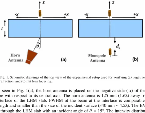
The refraction spectrum is measured by a setup consisting of an HP 8510C network analyzer, a standard high gain microwave horn antenna as the transmitter, and a monopole antenna as the receiver (Fig. 1(a)). The size of the monopole antenna is 3.9 cm, which is half of the wavelength (λ≅7.77cm) of the EM wave at a working frequency of f= 3.86 GHz. The 2D LHM structure is composed of Nx= 40, Ny= 20, and Nz= 10 unit cells, with lattice
spacings ax = ay= az= 9.3 mm. The top view of the experimental setup is given in Fig. 1(a),
the x and z directions are shown in the figure, whereas the y is directed to the out of page. The electric field is along the y direction, whereas the magnetic field and wave-vector are on the x-z plane.
Fig. 1. Schematic drawings of the top view of the experimental setup used for verifying (a) negative refraction, and (b) flat lens focusing.
As seen in Fig. 1(a), the horn antenna is placed on the negative side (-x) of the LHM structure with respect to its central axis. The horn antenna is 125 mm (1.6λ) away from the first interface of the LHM slab. FWHM of the beam at the interface is comparable to the wavelength and smaller than the size of the incident surface (340 mm ~ 4.5λ). The EM wave is sent through the LHM slab with an incident angle of θi = 15°. The intensity distribution of the refracted EM wave is scanned by a monopole antenna mounted to a 2D scanning table
with Δx = Δz = 2.5 mm steps. In our experiments we can only measure the power at a certain point, which corresponds to the time averaged intensity at that point.
At f = 3.86 GHz our 2D LHM is shown to have the highest transmission and lowest reflection values [10]. We have set 3.86 GHz as our working frequency, to assure that the effect of the reflections on our results is kept at minimum, including losses due to reflection. Figure 2(a) displays the measured refraction spectrum at 3.86 GHz. The intensities are normalized with respect to maximum intensity. The incident EM wave has a Gaussian beam profile centered at x = 0. Therefore, by measuring the shift of the outgoing beam, one can easily deduce whether the structure has a positive or negative index of refraction [14,17]. As clearly seen in Fig. 2(a), the center of the outgoing Gaussian beam is shifted to the left side of the center of the incident Gaussian beam, which due to Snell’s law, corresponds to negative refraction.
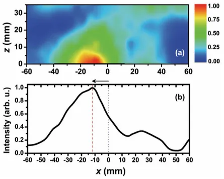
Fig. 2. (a) Spatial intensity distribution of an outgoing EM wave at 3.86 GHz along the x-z plane. (b) Intensity profile of an EM wave at the LHM-air interface (z = 0).
The point z = 0 in Fig. 2(a) corresponds to the second LHM-air interface. Figure 2(b) is the cross-section of Fig. 2(a) taken at z = 0, in other words it provides the intensity distribution of an EM wave at the LHM-air interface. As can be seen in Fig. 2(b), the center of the refracted Gaussian beam (red dashed line) is measured at -12.5 mm away from the center of the incident Gaussian beam (blue dotted line).
Snell’s law is an effective method for calculating refractive indices. Since we know the amount of the beam shift (-12.5 mm) and the thickness of the LHM slab, t = 91.2 mm, the angle of refraction can easily be calculated by using simple geometry, and found as θr ≅ 8°. The refractive index of LHM is then calculated from Snell’s law (nairsin
θ
i =neff sinθ
r) as neff = -1.86. The refractive index values were calculated by using the data in Ref. 9 for thesame structure by using the experimental results of refraction through a wedge shaped LHM sample (neff = -1.95) and the phase shift between different numbers of LHM layers (neff =
-2.00) [9]. The result neff = -1.86 obtained from a Gaussian beam shifting experiment is in good
3. Point focusing by a LHM flat lens
The presence of negative refraction enables the possibility that the slab structure may act like a lens for an omni-directional source. As described in detail in Ref. 18, a parallel-sided slab of material made of negative index metamaterial can focus EM waves. EM waves emerging from an omni-directional source located near such a lens will first be refracted through the first air-LHM interface and will come into focus inside the material. Then outgoing EM waves will face refraction again at the second LHM-air interface and the refracted beam will meet the optical axis of flat lens, where the second focusing will occur. If the lens is not thick enough, the focusing may not occur inside the lens, which in turn will result in a diverging beam instead of a converging beam, even if the material is negatively refracting. Therefore, the thickness of the lens plays a crucial role for observing flat lens behavior.
We have employed a LHM lens with 40×20×10 layers along the x, y and z directions. Along the propagation direction (z direction) the structure has 10 unit cells, and the thickness is t = 91.2 mm. The top view of the experimental setup for verifying focusing through a flat lens of LHM is schematically given in Fig. 1(b). A monopole antenna is used as the point source. The source is located away from the LHM lens at two different source distances of ds
= 39 mm (0.5λ) and ds = 78 mm (λ). The intensity distribution of an EM wave is scanned by another monopole antenna with Δx = Δz = 5 mm steps.
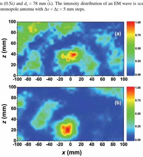
Fig. 3. Measured transmission spectra along the x-z plane for a point source located at (a) ds = 39 mm, and (b) ds = 78 mm away from the LHM lens. The x direction is parallel to the LHM lens where x = 0 is the optical axis of the flat lens, whereas the z direction is perpendicular to the LHM lens where z = 0 is the LHM-air interface.
The measured transmission spectra are shown in Fig. 3, with the intensities normalized with respect to the maximum intensity values. The point z = 0 corresponds to the LHM-air interface. Figure 3(a) provides the transmission spectrum for the omni-directional source located at ds = 39 mm away from the LHM lens. As seen in the figure, an image is formed at a
focal length of z = 40 mm (~0.52λ). For the case where the point source is placed at ds = 78 mm, the image is observed at z = 20 mm (~0.26 λ) (Fig. 3(b)). As the point source is moved away from the LHM flat lens, the focal length is shifted towards the flat lens, which is consistent with the imaging theory.
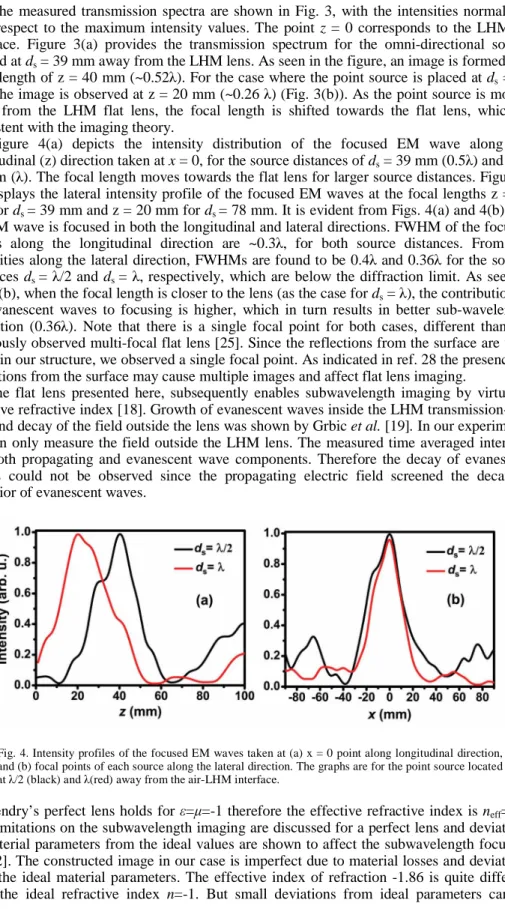
Figure 4(a) depicts the intensity distribution of the focused EM wave along the longitudinal (z) direction taken at x = 0, for the source distances of ds = 39 mm (0.5λ) and ds =
78 mm (λ). The focal length moves towards the flat lens for larger source distances. Figure 4 (b) displays the lateral intensity profile of the focused EM waves at the focal lengths z = 40 mm for ds = 39 mm and z = 20 mm for ds = 78 mm. It is evident from Figs. 4(a) and 4(b) that
the EM wave is focused in both the longitudinal and lateral directions. FWHM of the focused beams along the longitudinal direction are ~0.3λ, for both source distances. From the intensities along the lateral direction, FWHMs are found to be 0.4λ and 0.36λ for the source distances ds = λ/2 and ds = λ, respectively, which are below the diffraction limit. As seen in
Fig. 4(b), when the focal length is closer to the lens (as the case for ds = λ), the contribution of
the evanescent waves to focusing is higher, which in turn results in better sub-wavelength resolution (0.36λ). Note that there is a single focal point for both cases, different than the previously observed multi-focal flat lens [25]. Since the reflections from the surface are very small in our structure, we observed a single focal point. As indicated in ref. 28 the presence of reflections from the surface may cause multiple images and affect flat lens imaging.
The flat lens presented here, subsequently enables subwavelength imaging by virtue of negative refractive index [18]. Growth of evanescent waves inside the LHM transmission-line lens and decay of the field outside the lens was shown by Grbic et al. [19]. In our experiments we can only measure the field outside the LHM lens. The measured time averaged intensity has both propagating and evanescent wave components. Therefore the decay of evanescent waves could not be observed since the propagating electric field screened the decaying behavior of evanescent waves.
Fig. 4. Intensity profiles of the focused EM waves taken at (a) x = 0 point along longitudinal direction, and (b) focal points of each source along the lateral direction. The graphs are for the point source located at λ/2 (black) and λ(red) away from the air-LHM interface.
Pendry’s perfect lens holds for ε=μ=-1 therefore the effective refractive index is neff= -1. The limitations on the subwavelength imaging are discussed for a perfect lens and deviations of material parameters from the ideal values are shown to affect the subwavelength focusing [21,22]. The constructed image in our case is imperfect due to material losses and deviations from the ideal material parameters. The effective index of refraction -1.86 is quite different from the ideal refractive index n=-1. But small deviations from ideal parameters can be
permitted to achieve subwavelength imaging [22]. Subwavelength focusing is shown theoretically [23] and experimentally [15] for photonic crystals, where material parameters do not play an important role for overcoming the diffraction limit.
The paraxial approximation and ray diagrams are only applicable for the ideal case where n = -1. A recent theoretical analysis done by Lu et al. shows that negative group refraction is responsible for flat lens imaging therefore it is not meaningful to speak of Snell’s Law and geometrical optics if the refractive index is different from the ideal value n=-1 [28]. Therefore a focal point estimate by using geometrical optics will not work in these anisotropic structures.
LHM structures are all-angle negatively refracting materials, since the effective refractive index of these structures is determined by the effective material parameters, dielectric permittivity and magnetic permeability. All-angle negative refraction is essential for focusing the beam diverging from a point source [13]. Another crucial point is that the lens should not suffer much from the reflections at the LHM-air interface. The advantages of our flat lens in a nutshell are that: (1) The lens is constructed from an all-angle negative refractive index LHM slab, (2) it operates at a frequency where the transmission is at the maximum and the reflection is minimum, assuring that the experimental results are not any artifact of the reflections from the surface, (3) it is working in free space rather than an isolated waveguide environment, and (4) it enables sub-wavelength focusing by virtue of the negative refractive index.
4. Conclusion
In this paper, the negative refraction and the point focusing analysis of a 2D LHM flat lens is presented. The structure is shown to exhibit a negative refractive index at 3.86 GHz for a plane wave source. The Gaussian beam shift method and Snell’s law are employed to verify and calculate the negative index of refraction of the LHM. The effective refractive index value is found to be -1.86, which is consistent with the previously reported index of refraction values for the same structure. The flat lens behavior of a 2D LHM slab is investigated for a point source, located at two different distances away from the air-LHM interface. Sub-wavelength focusing is achieved along the longitudinal and lateral direction. A free space flat lens made of an all-angle negative refractive index LHM with low reflection is successfully demonstrated.
Acknowledgments
This work is supported by the European Union under the projects EU-DALHM, EU-NOE-METAMORPHOSE, EU-NOE-PHOREMOST, and TUBITAK under Project No. 104E090. One of the authors (Ekmel Ozbay) acknowledges partial support from the Turkish Academy of Sciences.