www.advmat.de
Record High External Quantum Efficiency of 19.2%
Achieved in Light-Emitting Diodes of Colloidal Quantum
Wells Enabled by Hot-Injection Shell Growth
Baiquan Liu, Yemliha Altintas, Lin Wang, Sushant Shendre, Manoj Sharma,
Handong Sun, Evren Mutlugun,* and Hilmi Volkan Demir*
Dr. B. Liu, Dr. S. Shendre, Dr. M. Sharma, Prof. H. V. Demir
Luminous! Centre of Excellence for Semiconductor Lighting and Displays School of Electrical and Electronic Engineering and School of Physical and Mathematical Sciences
Nanyang Technological University Singapore 639798, Singapore E-mail: [email protected]
Dr. Y. Altintas, Dr. M. Sharma, Prof. E. Mutlugun, Prof. H. V. Demir Department of Electrical and Electronics Engineering
Department of Physics
UNAM-Institute of Materials Science and Nanotechnology Bilkent University
Ankara 06800, Turkey E-mail: [email protected]
DOI: 10.1002/adma.201905824
last decade.[1–8] Thanks to their strong quantum confinement solely in the ver-tical direction, 2D CQWs possess many unique thickness-dependent optical char-acteristics including ultranarrow emis-sion with suppressed inhomogeneous broadening, giant oscillator strengths, extraordinarily large linear and nonlinear absorption cross-sections, and molar extinction coefficients.[9–14] All these supe-rior properties render CQWs to offer great potential for optoelectronic applications including solar energy harvesting, lasing, and light-emitting diodes (LEDs).[15–18]
CQW-LEDs are highly promising for display and lighting applications, owing to their high color purity with ultranarrow full-width at half-maximum (FWHM), easy solution-processed fabrication pro-cedures, and good compatibility with flexible electronics.[19–21] In the past few years, some efforts have been made to develop CQW-LEDs.[18–21] Nevertheless, the performance of CQW-LEDs lags far behind other types of LEDs showing the benchmark external quantum efficiency (EQE) of ≈20% including organic LEDs (OLEDs),[22–24] colloidal-quantum-dot LEDs (CQD-LEDs),[25–27] and perovskite LEDs (PeLEDs).[28–30] As a comparison, the record EQE of CQW-LEDs
Colloidal quantum wells (CQWs) are regarded as a highly promising class of optoelectronic materials, thanks to their unique excitonic characteristics of high extinction coefficients and ultranarrow emission bandwidths. Although the exploration of CQWs in light-emitting diodes (LEDs) is impressive, the performance of CQW-LEDs lags far behind other types of soft-material LEDs (e.g., organic LEDs, colloidal-quantum-dot LEDs, and perovskite LEDs). Herein, high-efficiency CQW-LEDs reaching close to the theoretical limit are reported. A key factor for this high performance is the exploitation of hot-injection shell (HIS) growth of CQWs, which enables a near-unity photoluminescence quantum yield (PLQY), reduces nonradiative channels, ensures smooth films, and enhances the stability. Remarkably, the PLQY remains 95% in solution and 87% in film despite rigorous cleaning. Through systematically understanding their shape-, composition-, and
device-engineering, the CQW-LEDs using CdSe/Cd0.25Zn0.75S core/HIS CQWs
exhibit a maximum external quantum efficiency of 19.2%. Additionally, a high luminance of 23 490 cd m−2, extremely saturated red color with the Commission Internationale de L’Eclairage (CIE) coordinates of (0.715, 0.283), and stable emission are obtained. The findings indicate that HIS-grown CQWs enable high-performance solution-processed LEDs, which may pave the path for future CQW-based display and lighting technologies.
The ORCID identification number(s) for the author(s) of this article can be found under https://doi.org/10.1002/adma.201905824.
Dr. Y. Altintas, Prof. E. Mutlugun
Department of Materials Science and Nanotechnology and Department of Electrical-Electronics Engineering
Abdullah Gül University Kayseri TR-38080, Turkey
E-mail: [email protected] Dr. L. Wang, Prof. H. Sun, Prof. H. V. Demir Division of Physics and Applied Physics School of Physical and Mathematical Sciences Nanyang Technological University
Singapore 637371, Singapore
Semiconductor colloidal quantum wells (CQWs), also com-monly nicknamed as nanoplatelets, have emerged as a new, highly promising family of optoelectronic materials over the
www.advmat.de www.advancedsciencenews.com
is 8.39%, accompanied with a maximum luminance of ≈100 cd m−2.[31] In fact, it is a challenge for CQW-LEDs to simultaneously achieve high efficiency and high luminance, especially for deep-red CQW-LEDs due to the low luminance perception of human eyes in those spectral ranges.[32] The low performance can be attributed to the use of inefficient CQW emitters, poor film morphology, and uncontrolled charge injec-tion and balance. Addiinjec-tionally, color-stable and saturated red CQW-LEDs have not been demonstrated yet.
To develop high-performance CQW-LEDs, superior CQW emitters are required. Most importantly, the CQWs should have an excellent photoluminescence quantum yield (PLQY), which is essential to warrant the high efficiency.[33] However, the PLQY of CQWs used in LEDs is not sufficiently high.[18–21,31,32] In the case of core CQWs, the surface nonradiative recombination sites will easily deteriorate the efficiency, leading to the ineffi-cient core-only-based CQW-LEDs.[18,20] To reduce surface traps, the growth of a semiconductor layer around the core CQWs is useful, which can increase the PLQY and decrease emission blinking at a single particle level.[34] In general, the colloidal atomic layer deposition (c-ALD) procedure is utilized to pro-duce the core/shell CQW heterostructures. However, c-ALD only allows for low PLQY and limited thermal stability since it occurs at room temperature.[5] Very recently, shell growth using hot-injection technique at high temperature is successfully implemented on CQWs, which provides highly uniform and crystalline core/shell CQWs having high PLQY, good stability, and narrow spectrum.[35] However, no efficient LED has been reported by utilizing the hot-injection shell (HIS)-based CQW emitters. In addition, the effect of the physical shape of CQWs on the device performance remains unknown, which might affect the film morphology of spin-coated CQWs in LEDs. Fur-thermore, the surface of previously reported CQW films is not smooth enough,[18–21,31,32] which may lead to detrimental cur-rent leakage and other losses.[36] Moreover, the employment of hybrid organic-inorganic device architectures is considered to be the most effective scheme to ensure high-efficiency CQD-LEDs.[37] However, in spite of high expectation, highly efficient CQW-LEDs with hybrid device architectures have not been reported yet.[31]
In this work, we show, for the first time, a CQW-LED with the EQE comparable to state-of-the-art OLEDs, CQD-LEDs, and PeLEDs. To obtain the high electroluminescence (EL) perfor-mance, core/HIS grown CQWs have been utilized, which is key to achieve near-unity PLQY, reduced nonradiative emission, smooth film, and improved stability. Importantly, even after five times of cleaning, the PLQY still remains as high as 95% in solution and 87% in solid state film, which is highly desirable to utilize them in LEDs. We propose that the shape of CQWs plays a crucial role in the performance of LEDs (e.g., the square CQW-based LEDs show higher efficiency than rod-like and rectangular CQW-based LEDs). We present that the optimized composition of core/HIS CQWs is significant to enhance the device efficiency by reducing the lattice mismatch between core and shell materials. With the understanding of the shape-, composition-, and device-engineering, the optimized CQW-LEDs based on CdSe/Cd0.25Zn0.75S core/HIS CQWs can exhibit an EQE of 19.23%, which is the most efficient CQW-LEDs reported thus far. Additionally, a high luminance of
23 490 cd m−2, an extremely saturated red color with the Com-mission Internationale de L’Eclairage (CIE) coordinates of (0.715, 0.283) along with highly stable emission at different luminance levels is achieved. Furthermore, to demonstrate the superiority of CQW emitters prepared by our HIS method, we have fabricated LEDs with core/shell CQWs synthesized via previously reported c-ALD method. Using the same device architecture, the CQW-LED with the core/c-ALD shell only exhibits a peak EQE of 0.19%, which is nearly 100-fold lower than that of core/HIS CQW-LEDs. It is also worth mentioning that the core/HIS CQW-LEDs exhibit a much better operational stability than the core/c-ALD shell CQW-LEDs.
The core CQWs, in their synthesized form, suffer from low stability and are prone to degradation due to their interac-tion with the surrounding medium, giving rise to suppressed PL by surface trap sites. This has tremendously affected the film QY of core CQWs only reaching 5%, despite the in-solution QY reached 70% by using halide ligands.[21] Hence, the overcoating shell material is usually needed for the c-ALD approach in CQWs. In this method, shell materials are conse-quently overcoated on the core CQW via sequential addition of cationic and anionic layers at room temperature. Although the method achieves the precise thickness control at atomic levels, the photophysical properties of the c-ALD coated CQWs are generally limited due to the consecutive washing steps and suc-cessive ligand exchange, which deteriorates the QY and photo-stability of the synthesized CQWs similar to the core CQW sys-tems. The HIS approach has been utilized for the synthesis of 0D CQDs successfully since early 90s, providing the uniform size distribution and high QY.[38] Recently, we have shown the optimized synthesis of shell growth using HIS approach,[35,39] which results in highly photostable and near-unity PLQY emit-ting core/shell CQWs.[40] The wide-bandgap shell (e.g., ZnS) provides high photostability and reduced Auger recombination for exciton harvesting applications. However, to reduce the lattice mismatch and strain build-up in core/shell CQWs, there is a definite need for the fine control of the core/shell inter-face.[39,41] To address the above-mentioned challenges, here we have introduced HIS approach with a precise control of CQW aspect ratio (AR) and shell alloying which lead to core/HIS grown materials, namely CdSe/Cd1−xZnxS CQWs. The alloying
mechanism allows for the fine tuning of the bandgap, which is demonstrated to be of critical importance for achieving high-performance LEDs.
CQWs can be synthesized in flat rod-like, rectangular and square shapes, which are named as high, mid, and low AR, respectively. To unveil the effect of CQW shape engineering on the performance of EL devices, we start with CdSe/ Cd0.15Zn0.85S core/HIS CQWs. In this approach, by changing the Cd-precursor as Cd-acetate, Cd-acetate monohydrate, and Cd-acetate dihydrate (see the Experimental Section in the Sup-porting Information), we achieve CQWs possessing the high, mid, and low AR. Further growth of alloyed shell leads to CdSe/ Cd0.15Zn0.85S core/shell CQWs corresponding to rod-like, rec-tangular, and square shape, respectively. Figure 1a presents the absorption and PL spectra of the high, mid, and low AR alloyed CdSe/Cd0.15Zn0.85S core/HIS CQWs. Although the shape varies, the PL emission peak and excitonic transition peak positions of the CQWs remained almost the same (638 ± 5 nm) since the
same core thickness and same shell composition are utilized. Figure 1b shows the transmission electron microscopy (TEM) image of the rod-like, rectangular, and square shaped CQWs. The AR of rod-like, rectangular, and square shaped CQWs are 3.2, 1.6, and 1.0, respectively (Table S1, Supporting Informa-tion). Atomic force microscopy (AFM) images presented in Figure 1c show the effect of the shape of CQWs on the film morphology, where the low AR CQWs has drastically enhanced the film morphology with reduced surface roughness. Further structural characterization of CdSe/Cd0.15Zn0.85S has been car-ried out and analyzed by X-ray diffraction (XRD) and X-ray photo electron spectroscopy (XPS) spectroscopy in Figures S1 and S2 (Supporting Information), respectively.
To understand the effect of the CQW shape on the EL per-formance, we have developed CQW-LEDs with the inverted hybrid organic–inorganic architecture (Figure 1d): indium tin oxide (ITO)/zinc oxide (ZnO, 25 nm)/CQWs (4 mg mL−1, 2000 rpm)/4,4-N,N-dicarbazolebiphenyl (CBP, 60 nm)/MoO3 (6 nm)/Al, where CdSe/Cd0.15Zn0.85S core/HIS CQWs with different shapes are used as the emitting layer (EML). CQWs were cleaned to reduce the ligands and then dispersed in toluene to facilitate spin coating onto ZnO electron trans-porting layer (ETL) without dissolution. ITO and Al func-tion as cathode and anode, respectively. CBP and MoO3 serve as the hole transporting layer (HTL) and hole injecting layer, respectively, which were deposited in a continuous manner by vacuum evaporation. Since ZnO possesses a high electron mobility of 1.8 × 10⁻³ cm2 V−1 s−1 and CBP has an excellent hole mobility of 2.0 × 10⁻³ cm2 V−1 s−1,[25,42] this simple hybrid device
architecture can provide sufficient electrons and holes to reach the CQW EML and then generate excitons for emission.
As shown in Figure 1e, the EL emission peaks of high, mid, and low AR-based CQW-LEDs are 648, 642, and 640 nm, respec-tively, corresponding to the CIE coordinates of (0.712, 0.286), (0.709, 0.288), and (0.707, 0.291). The EL spectra of high, mid, and low AR-based CQW-LEDs at various luminance are shown in Figure S3 (Supporting Information), where relatively stable emissions are yielded. The maximum EQE of high, mid, and low AR-based CQW-LEDs are 5.66%, 8.65%, and 11.19%, respectively (Figure 1e and Table 1). Therefore, the EL performance can be greatly affected by CQW shapes and the LED with low AR CQWs exhibits the best efficiencies among the three fabricated devices.
The origin of the best EQE achieved by low AR CQWs can be explained as follows. In LEDs, the EQE is usually defined as below[43]
r q
EQE=ηout⋅IQE=ηout⋅ ⋅ ⋅γ (1)
where ηout represents the outcoupling factor, IQE represents internal quantum efficiency, r represents the fraction of exci-tons that can potentially radiatively decay, q represents the PLQY of emitters, and γ represents the charge balance factor. For solution-processed LEDs, the film morphology of the active layer has a significant influence on the device performance.[32] Thus, the EQE of solution-processed LEDs (EQE’) can be written as follows[36,44]
α η γ
′ = ⋅ ⋅ ⋅ ⋅ ′r q
EQE out (2)
Figure 1. a) Absorption and PL spectra of high, mid, and low aspect ratio (AR) CdSe/Cd0.15Zn0.85S core/HIS CQWs. b) High-resolution TEM images (scale
www.advmat.de www.advancedsciencenews.com
where α represents the factor of film morphology extracted out from the charge balance factor to emphasize the effect of film roughness on the leakage current, γ ’ thus is the ratio of γ over α such that γ = α γ ’. In OLEDs, α is not considered due to the very smooth film formed by the vacuum-evaporated procedure.[45] The value of α is assumed to be ≤1 in solution-processed LEDs, where α = 1 indicates an excellent film morphology which has a negligible effect on the device performance. In the case of α = 1, EQE’ is the same as EQE, otherwise EQE’ is lower than EQE. Since ηout is not affected by the internal operation and r is ≈1, thanks to a slight energetic separation (<25 meV), for the “dark” and “bright” band-edge excitonic states,[46] the EQE’ of CQW-LEDs is mainly determined by γ ’, q, and α according to Equation (2).
The difference for the charge injection efficiency in high, mid and low AR-based CQW-LEDs is negligible, which can be attrib-uted to the almost similar valence band maximum and conduction band minimum of high, mid, and low AR CQWs due to the same chemical composition, similar device architectures, and similar cleaning procedure of CQWs.[47] Hence, the influence of γ ’ on the EQE of these CQW-LEDs can be ignored. In terms of the PLQY of emitters, the PLQY of low AR CQWs in the toluene solution is 92%, which is higher than that of high AR CQWs (86%) and mid AR CQWs (89%). Hence, low AR-based CQW-LEDs are able to show the high EQE. Furthermore, the average PL lifetime of low AR CQWs is 17.14 ns, which is higher than that of high AR (15.54 ns) and mid AR (16.75 ns) CQWs as measured from the time-resolved PL (TRPL) spectroscopy (Figure S4 and Table S2, Supporting Information). We attribute the long lifetime of PL to the fact that the shell growth on low AR structure is more superior to passivate nonradiative defects in CdSe/Cd0.15Zn0.85S, which enhances the efficiency of CQW-LEDs.[28]
The influence of the film morphology can be compared by the measurement of surface roughness of EML films using AFM.[25] To make evaluation at the same conditions as that of LED architectures, CQW films were spin-coated on ZnO. The root-mean-square (RMS) roughness of low AR CQW film is 2.43 nm (Figure 1c), which is much smoother than that of high AR (5.74 nm) and mid AR (3.44 nm) CQW films (Figure S5, Supporting Information). As a consequence, the likelihood of morphologically induced electrical shorts in low-AR-based CQW-LEDs is remarkably reduced, enhancing the device perfor-mance.[48] To give an insightful evidence for the phenomenon
that low AR CQWs exhibit the smoothest film, the high-angle annular dark-field (HAADF) TEM of high and low AR CQWs have been measured (Figure S6, Supporting Information). The surface coverage and edge-down formation of low AR CQWs are much better than those of high AR CQWs, which enhances the film quality. Therefore, it is reasonable that low AR based CQW-LEDs exhibits the highest EQE among these three devices. On the other hand, the stacking in CQW films is detrimental to the efficiency through fast nonradiative exciton transfer giving defected sub-populations, which act as exciton sinks, undermining the efficiency of LEDs.[16,49] As HAADF TEM images clearly show in Figure S6 (Supporting Informa-tion), negligible stacking is observed in low AR CQWs while stacking exists in high AR CQWs, suppressing the efficiency reduction in low AR devices.[50,51] Nevertheless, despite low AR-based CQW-LEDs show superior performance among all devices possessing different ARs, further investigations are needed to better understand their role in the high performance.
After optimizing the shape of core/shell CQWs, additional improvements are envisioned by manipulating the compo-sition of shell alloying on optimized low AR CQWs. First, to reveal the effect of the bandgap alignment, we have synthesized low AR CdSe/ZnS core/HIS CQWs. The PL emission peak for CdSe/ZnS is at 613 nm, and the XRD analysis shows the ZnS presence in the shell (Figure S7, Supporting Information).
Figure 2a presents the bandgap alignment of the CQW-LEDs
using CdSe/Cd1−xZnxS as emitters, where large electron and
hole injection barriers exist at the interface of ZnO-CdSe/ZnS and CdSe/ZnS-CBP, respectively. Using the same device archi-tecture, the EL spectra of CdSe/ZnS-based CQW-LEDs show the emission peak at 618 nm (Figure 2b), possessing CIE color coordinates of (0.674, 0.324). The maximum EQE of CdSe/ZnS-based CQW-LEDs is 4.69% (Figure 2c), which is lower than that of CdSe/Cd0.15Zn0.85S-based CQW-LEDs (11.19%). This is expected since the charge injection may be limited by the align-ment of the energy band levels and reduced PLQY (85%) in the case of CdSe/ZnS CQWs.[52] To have a better engineering of the bandgap alignment, we have focused on the synthesis of low AR CdSe/Cd1−xZnxS core/HIS CQWs with the alloyed shell
in the structure to reduce the lattice mismatch and favor the balanced charge injection.
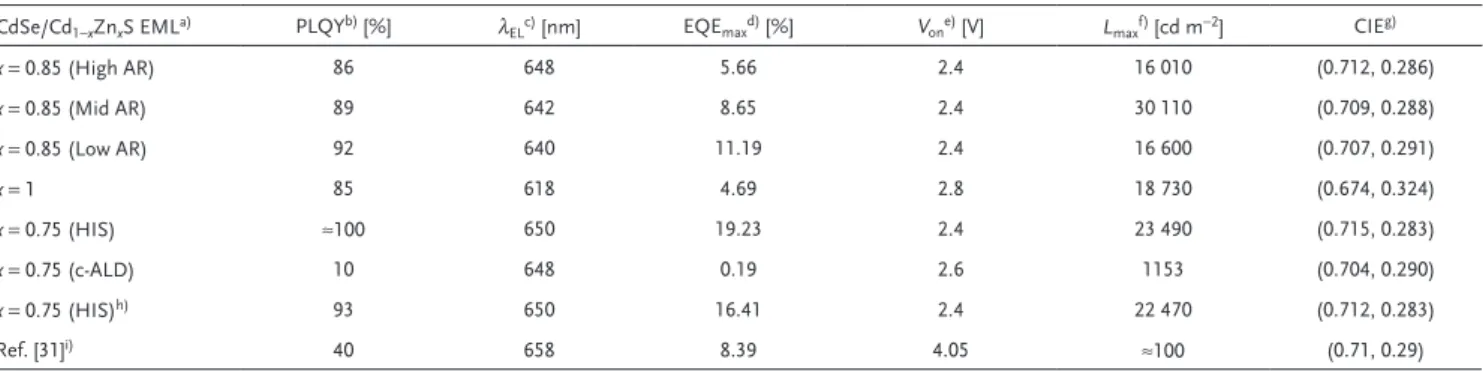
In this regard, we successfully synthesized core/HIS CQWs having different alloying compositions in the shell. Optimized Table 1. Summary of LED performances.
CdSe/Cd1−xZnxS EMLa) PLQYb) [%] λELc) [nm] EQEmaxd) [%] Vone) [V] Lmaxf) [cd m−2] CIEg)
x = 0.85 (High AR) 86 648 5.66 2.4 16 010 (0.712, 0.286) x = 0.85 (Mid AR) 89 642 8.65 2.4 30 110 (0.709, 0.288) x = 0.85 (Low AR) 92 640 11.19 2.4 16 600 (0.707, 0.291) x = 1 85 618 4.69 2.8 18 730 (0.674, 0.324) x = 0.75 (HIS) ≈100 650 19.23 2.4 23 490 (0.715, 0.283) x = 0.75 (c-ALD) 10 648 0.19 2.6 1153 (0.704, 0.290) x = 0.75 (HIS)h) 93 650 16.41 2.4 22 470 (0.712, 0.283) Ref. [31]i) 40 658 8.39 4.05 ≈100 (0.71, 0.29)
a)The EML used in LEDs; b)The PLQY of CQWs; c)EL emission peak; d)Maximum EQE; e)Turn-on voltage (the voltage when the luminance is >0.01 cd m−2); f)Maximum
low AR cores were used to grow HIS for these experiments and CdSe/Cd0.25Zn0.75S core/HIS was found to be the best CQW emitter for the enhancement of balanced charge injec-tion. With the increasing of Cd in the shell, the bandgap of CdSe/Cd1−xZnxS is decreasing since the bandgap of CdS
is narrower than that of ZnS (e.g., the bandgap of CdSe/ Cd0.25Zn0.75S is 1.87 eV),[51] as shown in Figure S8 (Supporting Information). According to the ultraviolet photoelectron spec-troscopic (UPS) measurement (Figure S9 and Table S3, Sup-porting Information), the energy level of CdSe/Cd0.25Zn0.75S can be more effectively matched with the device architecture thanks to the reduced charge injection barrier. The average PL lifetime of CdSe/Cd0.25Zn0.75S is 26.44 ns, which is longer than that of low AR CdSe/Cd0.15Zn0.85S (17.14 ns) and CdSe/ ZnS (14.22 ns) (Figure S10 and Table S4, Supporting Infor-mation). These results clearly indicate the reduced nonra-diative channel with optimized alloying composition in shell region.[28] Furthermore, RMS roughness of CdSe/Cd
0.25Zn0.75S CQW film is very low (2.23 nm) (Figure S11, Supporting Information). The PLQY of as-synthesized CdSe/Cd0.25Zn0.75S CQWs is near-unity in solution, which remains still as high as 95% in solution and 87% in film even after 5 times clean-ings (Figure 2d). These values are the highest among CQWs, to the best of our knowledge. Since emitters with a near-unity PLQY are ideal for LEDs, CQW-LEDs have been developed with optimized CdSe/Cd0.25Zn0.75S, where the device architecture is similar to CdSe/Cd0.15Zn0.85S-based devices except for the EML (i.e., ITO/ZnO/CdSe/Cd0.25Zn0.75S/CBP/MoO3/Al). The
cross-sectional scanning electron microscopy (SEM) image of CQW-LEDs is depicted in Figure S12 (Supporting information), where the thickness of EML is very thin (≈20 nm) compared with the thickness of active layer in solar cells (e.g., 200 nm).[53] As shown in Figure 2b, the EL emission peak of CdSe/ Cd0.25Zn0.75S-based CQW-LEDs is 650 nm and the FWHM is as narrow as 26 nm, The maximum EQE of CdSe/Cd0.25Zn0.75 S-based CQW-LEDs is 19.23% (Figure 2c), which is the first report to demonstrate that the EQE of CQW-LEDs can be close to the theoretical maximum of 20% from planar surfaces without any light extraction features. The high efficiency can be ascribed to the high PLQY, excellent film quality and engineered bandgap alignment through the alloyed shell composition adjustment of CQWs. Figure 2e provides the histogram of the maximum EQE values for 30 devices based on CdSe/Cd0.25Zn0.75S, where the average maximum EQEs is 15.61%, demonstrating the good performance reproducibility of these CQW-LEDs. The turn-on voltage is 2.4 V, while the maximum luminance is 23 490 cd m−2 (Figure 2f). Therefore, CQW-LEDs have been demonstrated to simultaneously exhibit high efficiency and high luminance in the deep red spectrum range, which is unprecedented.
On top of the above discussions, the key factor of the high EQE is the exploitation of the HIS technique. As an evidence, we have used CdSe/Cd0.25Zn0.75S core/c-ALD shell CQWs as the emitter to develop LEDs, where the device architecture is similar to that of CdSe/Cd0.25Zn0.75S core/HIS CQW-LEDs except for the EML. To make an appropriate comparison, the shell thickness of CdSe/Cd0.25Zn0.75S core/c-ALD shell is Figure 2. a) Schematic flat-band energy diagram of CQW-LEDs. The unit of energy is eV. The values of CdSe/Cd1−xZnxS are obtained by UPS while
others are taken from the literature.[20,25] b) EL spectra of CQW-LEDs with varying shell composition at 100 cd m−2. c) EQE of CQW-LEDs with varying
shell composition. d) Evolution of the PLQY of CdSe/Cd0.25Zn0.75S core/HIS CQWs. e) EQE histogram of the CdSe/Cd0.25Zn0.75S core/HIS CQW-LEDs.
www.advmat.de www.advancedsciencenews.com
controlled to be the same as that of CdSe/Cd0.25Zn0.75S core/ HIS. As shown in Figure 2b, the EL emission peak of CdSe/ Cd0.25Zn0.75S core/c-ALD shell CQW-LEDs is 648 nm. The maximum EQE of CdSe/Cd0.25Zn0.75S core/c-ALD shell CQW-LEDs is 0.19% (Figure 2c), which is nearly 100-fold lower than that of CdSe/Cd0.25Zn0.75S core/HIS device. Addition-ally, the maximum luminance is 1153 cd m−2, which is about 20-fold lower than that of CdSe/Cd0.25Zn0.75S core/HIS device (Figure S13, Supporting Information). Therefore, the CQW-LEDs fabricated using HIS technique perform far better com-pared with the c-ALD approach.
To understand the origin of the above phenomenon, we have further compared the optical and material structure of the CdSe/Cd0.25Zn0.75S core/c-ALD and core/HIS samples. Figure 3a,b present the absorption and PL spectra of the CdSe/
Cd0.25Zn0.75S core/c-ALD and core/HIS along with their TEM image, respectively. Despite the PL emission peaks being almost the same (i.e., 639 and 644 nm for core/c-ALD and core/HIS CQWs, respectively), the PLQY of CdSe/Cd0.25Zn0.75S core/c-ALD shell is only 10%, leading to the poor device effi-ciency.[54] However, it is deserved to point out that such PLQY is consistent with that of reported core/shell CQWs utilizing c-ALD, with levels in the range of 0.5–11%.[55,56] The XRD and XPS characterizations of the CdSe/Cd0.25Zn0.75S core/c-ALD and core/HIS are shown in Figures 3c,d, respectively. Both XRD and XPS studies reveal that Zn composition is very low in the c-ALD approach, since it cannot penetrate into the struc-ture due to the low temperastruc-ture shell growth route followed in c-ALD approach. In comparison, both XRD and XPS analysis
present that the Zn is incorporated into the structure for HIS-grown CQWs. XPS elemental analysis presents that there is a 2% Zn in the c-ALD and 20% (counted from all elements in the core/shell structure) in the HIS approach even though ini-tial same precursor compositions are employed. Also as shown in the XRD analysis, CdSe/Cd0.25Zn0.75S core/c-ALD shell reveals the structure of the CdSe/CdS rather than CdSe/ZnS. The average PL lifetime of the CdSe/Cd0.25Zn0.75S core/c-ALD shell is 7.35 ns, which is much lower than that of CdSe/ Cd0.25Zn0.75S core/HIS (26.44 ns) (Figure 3e), indicating an increased nonradiative recombination of excitons.[28] As shown in Figure 3f, the RMS roughness of c-ALD-shell-based film is as rough as 3.70 nm. Consequently, CQW-LEDs using CdSe/ Cd0.25Zn0.75S core/c-ALD shell show poor performance. How-ever, it is deserved to note that no CQW film used in LEDs has been previously demonstrated to exhibit an RMS roughness of ≤3 nm,[18–21,31,32] indicating that the HIS technique (e.g., an RMS roughness of 2.23 nm) provides a new pathway to effec-tively smoothen the film surface.
For the practical display and lighting applications, stable colors are required.[57,58] Additionally, to satisfy the require-ment of the International Telecommunication Union Recom-mendation BT 2020 (Rec. 2020) standard for new-generation ultrahigh definition TVs, the CIE 1931 color coordinates for the red emitters should be close to (0.708, 0.292).[59] As shown in Figure 4a, CdSe/Cd0.25Zn0.75S core/HIS CQW-LEDs have a very stable EL emission. In addition, no emissions were observed from the neighboring charge transporting layers, indicating that the injected holes and electrons are recombined at the Figure 3. Comparison of different shell growths on CdSe/Cd0.25Zn0.75S using c-ALD and HIS techniques. a,b) Absorption and PL spectra of core/c-ALD
shell CQWs (a) and core/HIS CQWs (b). Inset: the TEM images (scale bar: 20 nm). c) XRD, d) XPS, and e) TRPL analyses of c-ALD- and HIS-grown CQWs. f) AFM image of core/c-ALD shell CQWs.
CQWs. The photograph given in the inset of Figure 4a displays a bright red emission from an operating CQW-LED at about 5000 cd m−2. The CIE coordinates remain almost unchanged with increasing luminance (Figure 4b). The total CIE change is only 0.004 in x and 0.002 in y as the luminance increases from 10 to 10 000 cd m−2, which is the smallest variation for CQW-LEDs to date. At the display-related luminance of 100 cd m−2, the CIE 1931 coordinates of CdSe/Cd0.25Zn0.75S core/HIS CQW-LEDs are (0.715, 0.283), exhibiting an exceptionally sat-urated red emission (Figure 4c). As a result, the color gamut covers 101% of the Rec. 2020 standard in the CIE 1931 color space. For the National Television System Committee (NTSC) standard, the color gamut is as high as 110% in the CIE 1931 color space. Therefore, extremely color-stable and saturated red CQW-LEDs which are highly advantageous for display technol-ogies have been demonstrated here.
The operation lifetime of previous CQW-LEDs is usually very poor. For example, only one CQW-LED was reported with life-time data in the literature till now which had a lifelife-time of 270 s at an initial luminance of 100 cd m−2.[20] CdSe/Cd
0.25Zn0.75S core/HIS CQW-LEDs, simply encapsulated by ultraviolet-cur-able epoxy resin, show a much better operational stability. As shown in Figure 4d, for a typical device tested at a constant driving current density of ≈80 mA cm−2, which corresponds to an initial luminance, L0, of 5000 cd m−2, the half lifetime,
T50, defined as the time for the luminance to decrease to L0/2 is 130 s. By using the relation L0nT50 = L1nT and assuming an acceleration factor of n = 1.5,[25] T
50 for this device at 100 cd m−2 is predicted to be 12.8 h, which is 170-fold longer than that
of previous CQW-LEDs.[20] Such an important enhancement for the lifetime is attributed to the excellent stability of CQWs prepared by the HIS approach. In contrast, the lifetime of CdSe/Cd0.25Zn0.75S core/c-ALD shell CQW-LEDs is only 480 s at an initial luminance of 100 cd m−2 (Figure S14, Supporting Information).
Compared to CQD-LEDs,[25] the stability of our CQW-LEDs (12.8 h) may be further improved. To comprehend the origin of this issue, we have found that the stability is related to the device architecture as one of the important factors. CBP is an unstable organic material, which is prone to crystallization because of a low glass transition temperature (Tg) of 62 °C, resulting in morphological instability.[60] In addition, CBP molecules can be electrochemically decomposed during device operation, where decomposed species act as nonradiative recom-bination centers and/or luminance quenchers, decreasing the stability.[61] To overcome this problem, we have used an HTL
N,N ′-di-(1-naphthyl)-N,N ′-diphenyl-(1,1’-biphenyl)-4,4’-diamine (NPB) exhibiting an enhanced Tg of 98 °C and good morpho-logical stability to develop CQW-LEDs.[62] As expected, the life-time is improved (24.6 h), as shown in Figure S15 (Supporting Information). Nevertheless, a low EQE of 7.2% is obtained (Figure S16, Supporting Information). Furthermore, a stepwise HTL NPB (30 nm)/4,4′,4″-tris(carbazol-9-yl)-triphenylamine (TCTA, 30 nm) has been used to develop CQW-LEDs, since TCTA has a HOMO (5.7 eV)[63] locating between the HOMO of NPB (5.3 eV)[62] and the valence band maximum of CdSe/Cd0.25Zn0.75S. Additionally, TCTA exhibits a high mor-phological stability (Tg = 152 °C).[64] As shown in Figure S17 Figure 4. a) EL spectra of CdSe/Cd0.25Zn0.75S core/HIS CQW-LEDs at various luminances. Inset: a photograph of CQW-LEDs under bias. b) CIE
coor-dinates as a function of the luminance. c) Position of the coorcoor-dinates of (0.715, 0.283) in the CIE diagram. d) Lifetime study of CdSe/Cd0.25Zn0.75S
www.advmat.de www.advancedsciencenews.com
(Supporting Information), T50 for this device at 100 cd m−2 is 57.0 h, which is 4.5-fold longer than that of CBP-based CQW-LEDs. As a comparison, the stability of our NPB/TCTA-based device is better than that of state-of-the-art red all-inorganic PeLEDs, which show a lifetime of 3 h at 100 cd m−2.[59] The EQE of NPB/TCTA-based device is improved to be 15.7% (Figure S18, Supporting Information). Based on these findings, the stability of CQW-LEDs is expected to be further enhanced if the thick-ness of each layer for the stepwise HTL is optimized and more stable hole transport materials can be obtained. Furthermore, it is required to study more in-depth underlying phenomena resulting in the compromise of stability and efficiency in our future work.
Apart from the role of different hole and electron transport layers in the stability of CQW-LEDs, the nature of EML may also affect the overall stability. With the similar device archi-tecture (ITO/ZnO/emitter/CBP/MoO3/Al), PeLEDs exhibit a lifetime of 0.1 h at 100 cd m−2.[65] Even with the same emitter composition, the c-ALD-based CQW-LED shows a poor life-time of 480 s. Hence, emitters should have an influence on the stability. Despite the RMS roughness of the HIS-based CdSe/Cd0.25Zn0.75S is very low, it is still higher than that of CQDs which can exhibit an RMS <1 nm.[66] Since the smooth surface is beneficial to the stability,[67] further improvement of CQW emitters with improved film quality may achieve more stable devices. Furthermore, since we simply encapsulated CQW-LEDs by using only ultraviolet-curable epoxy resin and cover glass, the amount of oxygen and humidity is increased during device operation since the Joule heating generated at high voltages plays a negative role in the encapsulation. Oxygen and humidity are typically detrimental to many kinds of CQD and CQW films unless using extra protection materials as silica or resistant ligands (obtained via ligand exchange procedures). While such protection materials or ligand-exchange procedures decrease PLQY of films and charge injection into the emitter, they can increase the film stability. The PLQY of our CQWs is decreased with the exposure of air (Figure 2d) and the PLQY of CQW films is about 50% after 96 h exposure in the air envi-ronment. Therefore, the stability of CQW-LEDs can be further enhanced if more advanced encapsulation technology were used and/or CQWs were synthesized in a way not to be negatively affected by oxygen and humidity, which is under investigation.
To further understand the stability of HIS-grown CQWs, the ligand-cleaned CdSe/Cd0.25Zn0.75S core/HIS CQW solutions have been stored for 1 year under ambient condition and air environment. Despite for such long time storage, the PLQY of cleaned CQWs remains almost stable (93%). The stored CQWs have also been tested in LEDs with the same device architec-ture (ITO/ZnO/CQWs/CBP/MoO3/Al). The maximum EQE of LEDs with CQWs stored for a year is still as high as 16.41% (Figure 4e), which also indicates the excellent reproducibility of core/HIS CQW-LEDs. Additionally, LEDs with stored CQWs exhibit a turn-on voltage of 2.4 V and maximum luminance of 22 470 cd m−2 (Figure 4f), which are almost similar to LEDs using fresh CQWs. Furthermore, the similar CIE coordinates of (0.712, 0.283) and stable emission are yielded (Figure S19, Sup-porting Information).
Finally, to demonstrate the universality that core/HIS CQWs can be applied to various device architecture, another LED has been fabricated with the architecture of ITO/ZnO/EML/1-bis
[4-[N,N-di(4-tolyl)amino]phenyl]-cyclohexane (TAPC)/MoO3/Al, where 60 nm TAPC is functioned as the HTL. By using CdSe/ Cd0.25Zn0.75S core/HIS as the EML, the maximum EQE of TAPC-based CQW-LEDs is 9.51% (Figure S20, Supporting Infor-mation), which is an order of magnitude higher than that of recent PeLEDs with the similar device architecture.[68] Therefore, core/HIS COWs can be extended to develop efficient LEDs with different device architectures. However, the efficiency of TAPC-based CQW-LEDs is lower than that of CBP-TAPC-based device, which can be attributed to the large hole injection barrier between TAPC and CQWs. On the other hand, these results also indi-cate that the device engineering plays a crucial role in the perfor-mance of CdSe/Cd0.25Zn0.75S core/HIS-based CQW-LEDs.
To conclude, we have demonstrated the best-performing CQW-LEDs with record efficiency, high luminance, outstanding reproducibility, impressive lifetime, exceptionally stable, and saturated red emission, whose EQE is comparable to that of state-of-the-art OLEDs, CQD-LEDs, and PeLEDs. Such remark-able optoelectronic performance is attained via the exploitation of the HIS technique, which renders the CQWs with a near-unity PLQY, reduced nonradiative recombination, smooth film surface, and enhanced stability. By understanding the shape-, composition-, and device-engineering, the CQW-LEDs based on CdSe/Cd0.25Zn0.75S core/HIS CQWs can simultaneously possess a high efficiency of 19.23% and high luminance of 23 490 cd m−2. In addition, an extremely saturated red color with the CIE coordinates of (0.715, 0.283) and highly stable emission are realized. The findings are promising to be extended to var-ious-color CQW-LEDs and imply that HIS-grown CQWs enable high-performance solution-processed LEDs, which may pave the path for future CQW-based display and lighting technologies.
Supporting Information
Supporting Information is available from the Wiley Online Library or from the author.
Acknowledgements
B.L. and Y.A. contributed equally to this work. This research was supported by the National Research Foundation, Prime Minister’s Office, Singapore under its Investigatorship Program (NRF-NRFI2016-08) and the Singapore Agency for Science, Technology and Research (A*STAR) SERC Pharos Program under Grant No. 152 73 00025. E.M. acknowledges TUBA GEBIP. H.V.D. gratefully acknowledges TUBA.
Conflict of Interest
The authors declare no conflict of interest.
Keywords
colloidal quantum wells, core/shell structures, hot injection, light-emitting diodes, nanoplatelets
Received: September 6, 2019 Revised: November 13, 2019 Published online: December 23, 2019
[1] S. Ithurria, M. D. Tessier, B. Mahler, R. P. S. M. Lobo, B. Dubertret, A. L. Efros, Nat. Mater. 2011, 10, 936.
[2] J. Q. Grim, S. Christodoulou, F. Di Stasio, R. Krahne, R. Cingolani, L. Manna, I. Moreels, Nat. Nanotechnol. 2014, 9, 891.
[3] C. E. Rowland, I. Fedin, H. Zhang, S. K. Gray, A. O. Govorov, D. V. Talapin, R. D. Schaller, Nat. Mater. 2015, 14, 484.
[4] A. Riedinger, F. D. Ott, A. Mule, S. Mazzotti, P. N. Knusel, S. J. P. Kress, F. Prins, S. C. Erwin, D. J. Norris, Nat. Mater. 2017,
16, 743.
[5] M. Sharma, K. Gungor, A. Yeltik, M. Olutas, B. Guzelturk, Y. Kelestemur, T. Erdem, S. Delikanli, J. R. McBride, H. V. Demir,
Adv. Mater. 2017, 29, 1700821.
[6] B. Guzelturk, M. Pelton, M. Olutas, H. V. Demir, Nano Lett. 2019,
19, 277.
[7] O. Erdem, K. Gungor, B. Guzelturk, I. Tanriover, M. Sak, M. Olutas, D. Dede, Y. Kelestemur, H. V. Demir, Nano Lett. 2019, 19, 4297. [8] B. Guzelturk, Y. Kelestemur, M. Olutas, S. Delikanli, H. V. Demir,
ACS Nano 2014, 8, 6599.
[9] S. Christodoulou, J. I. Climente, J. Planelles, R. Brescia, M. Prato, B. Martin-Garcia, A. H. Khan, I. Moreels, Nano Lett. 2018, 18, 6248. [10] A. Riedinger, D. R. Ochsenbein, P. N. Knüsel, S. C. Erwin,
M. Mazzotti, D. J. Norris, Nano Lett. 2017, 17, 6870. [11] S. Ithurria, B. Dubertret, J. Am. Chem. Soc. 2008, 130, 16504. [12] A. Yeltik, S. Delikanli, M. Olutas, Y. Kelestemur, B. Guzelturk,
H. V. Demir, J. Phys. Chem. C 2015, 119, 26768.
[13] M. Olutas, B. Guzelturk, Y. Kelestemur, A. Yeltik, S. Delikanli, H. V. Demir, ACS Nano 2015, 9, 5041.
[14] Y. Kelestemur, B. Guzelturk, O. Erdem, M. Olutas, K. Gungor, H. V. Demir, Adv. Funct. Mater. 2016, 26, 3570.
[15] S. Delikanli, G. Yu, A. Yeltik, S. Bose, T. Erdem, J. Yu, O. Erdem, M. Sharma, V. K. Sharma, U. Quliyeva, S. Shendre, C. Dang, D. H. Zhang, T. C. Sum, W. Fan, H. V. Demir, Adv. Funct. Mater.
2019, 29, 1901028.
[16] B. Guzelturk, O. Erdem, M. Olutas, Y. Kelestemur, H. V. Demir, ACS
Nano 2014, 8, 12524.
[17] C. She, I. Fedin, D. S. Dolzhnikov, P. D. Dahlberg, G. S. Engel, R. D. Schaller, D. V. Talapin, ACS Nano 2015, 9, 9475.
[18] F. Fan, P. Kanjanaboos, M. Saravanapavanantham, E. Beauregard, G. Ingram, E. Yassitepe, M. M. Adachi, O. Voznyy, A. K. Johnston, G. Walters, G. Kim, Z. -H. Lu, E. H. Sargent, Nano Lett. 2015, 15, 4611. [19] B. Liu, S. Delikanli, Y. Gao, D. Dede, K. Gungor, H. V. Demir, Nano
Energy 2018, 47, 115.
[20] B. Liu, M. Sharma, J. Yu, S. Shendre, C. Hettiarachchi, A. Sharma, A. Yeltik, L. Wang, H. Sun, C. Dang, H. V. Demir, Small 2019, 15, 1901983.
[21] M. Dufour, J. Qu, C. Greboval, C. Methivier, E. Lhuillier, S. Ithurria,
ACS Nano 2019, 13, 5326.
[22] H. Uoyama, K. Goushi, K. Shizu, H. Nomura, C. Adachi, Nature
2012, 492, 234.
[23] X. Ai, E. W. Evans, S. Dong, A. J. Gillett, H. Guo, Y. Chen, T. J. H. Hele, R. H. Friend, F. Li, Nature 2018, 563, 536.
[24] D.-H. Kim, A. D’aléo, X. K. Chen, A. D. S. Sandanayaka, D. Yso, L. Zhao, T. Komino, E. Zaborova, G. Canard, Y. Tsuchiya, E. Choi, J. W. Wu, F. Fages, J -L. Bredas, J.-C. Ribierre, C. Adachi, Nat.
Photonics 2018, 12, 98.
[25] X. L. Dai, Z. X. Zhang, Y. Z. Jin, Y. Niu, H. J. Cao, X. Y. Liang, L. W. Chen, J. P. Wang, X. G. Peng, Nature 2014, 515, 96.
[26] Y. X. Yang, Y. Zheng, W. R. Cao, A. Titov, J. Hyvonen, J. R. Manders, J. G. Xue, P. H. Holloway, L. Qian, Nat. Photonics 2015, 9, 259. [27] H. Shen, Q. Gao, Y. Zhang, Y. Lin, Q. Lin, Z. Li, L. Chen, Z. Zeng,
X. Li, Y. Jia, S. Wang, Z. Du, L. S. Li, Z. Zhang, Nat. Photonics 2019,
13, 192.
[28] K. Lin, J. Xing, L. N. Quan, F. P. G. Arquer, X. Gong, J. Lu, L. Xie, W. Zhao, D. Zhang, C. Yan, W. Li, X. Liu, Y. Lu, J. Kirman, E. H. Sargent, Q. Xiong, Z. Wei, Nature 2018, 562, 245.
[29] Y. Cao, N. Wang, H. Tian, J. Guo, Y. Wei, H. Chen, Y. Miao, W. Zou, K. Pan, Y. He, H. Cao, Y. Ke, M. Xu, Y. Wang, M. Yang, K. Du, Z. Fu, D. Kong, D. Dai, Y. Jin, G. Li, H. Li, Q. Peng, J. Wang, W. Huang,
Nature 2018, 562, 249.
[30] W. Xu, Q. Hu, S. Bai, C. Bao, Y. Miao, Z. Yuan, T. Borzda, A. J. Barker, E. Tyukalova, Z. Hu, M. Kawecki, H. Wang, Z. Yan, X. Liu, X. Shi, K. Uvdal, M. Fahaman, W. Zhang, M. Duchamp, J. -M. Liu, A. Petrozza, J. Wang, L. -M. Liu, W. Huang, F. Gao, Nat.
Photonics 2019, 13, 418.
[31] U. Giovanella, M. Pasini, M. Lorenzon, F. Galeotti, C. Lucchi, F. Meinardi, S. Luzzati, B. Dubertret, S. Brovelli, Nano Lett. 2018,
18, 3441.
[32] Z. Chen, B. Nadal, B. Mahler, H. Aubin, B. Dubertret, Adv. Funct.
Mater. 2014, 24, 295.
[33] X. Yang, X. Zhang, J. Deng, Z. Chu, Q. Jiang, J. Meng, P. Wang, L. Zhang, Z. Yin, J. You, Nat. Commun. 2018, 9, 570.
[34] M. Pelton, J. J. Andrews, I. Fedin, D. V. Talapin, H. Leng, S. K. O’Leary, Nano Lett. 2017, 17, 6900.
[35] Y. Altintas, U. Quliyeva, K. Gungor, O. Erdem, Y. Kelestemur, E. Mutlugun, M. V. Kovalenko, H. V. Demir, Small 2019, 15, 1804854. [36] H. Wang, X. Zhang, Q. Wu, F. Cao, D. Yang, Y. Shang, Z. Ning,
W. Zhang, W. Zheng, Y. Yan, S. V. Kershaw, L. Zhang, A. L. Rogach, X. Yang, Nat. Commun. 2019, 10, 665.
[37] B. S. Mashford, M. Stevenson, Z. Popovic, C. Hamilton, Z. Zhou, C. Breen, J. Steckel, V. Bulovic, M. Bawendi, S. Coe-Sullivan, S. P. T. Kazlas, Nat. Photonics 2013, 7, 407.
[38] C. B. Murray, D. J. Norris, M. G. Bawendi, J. Am. Chem. Soc. 1993,
115, 8706.
[39] Y. Altintas, K. Gungor, Y. Gao, M. Sak, U. Quliyeva, G. Bappi, E. Mutlugun, E. H. Sargent, H. V. Demir, ACS Nano 2019, 13, 10662. [40] A. A. Rossinelli, A. Riedinger, P. Marqués-Gallego, P. N. Knüsel,
F. V. Antolinez, D. J. Norris, Chem. Commun. 2017, 53, 9938. [41] A. A. Rossinelli, H. Rojo, A. S. Mule, M. Aellen, A. Cocina,
E. De Leo, R. Schäublin, D. J. Norris, Chem. Mater. 2019, 31, 9567. [42] D. Zhang, L. Duan, D. Zhang, J. Qiao, G. Dong, L. Wang, Y. Qiu,
Org. Electron. 2013, 14, 260.
[43] B. Liu, L. Wang, D. Gao, J. Zou, H. Ning, J. Peng, Y. Cao, Light: Sci.
Appl. 2016, 5, e16137.
[44] N. K. Kumawat, N. Jain, A. Dey, K. L. Narasimhan, D. Kabra, Adv.
Funct. Mater. 2017, 27, 1603219.
[45] B. Liu, H. Nie, X. Zhou, S. Hu, D. Luo, D. Gao, J. Zou, M. Xu, L. Wang, Z. Zhao, A. Qin, J. Peng, H. Ning, Y. Cao, B. Z. Tang, Adv.
Funct. Mater. 2016, 26, 776.
[46] Y. Shirasaki, G. J. Supran, M. G. Bawendi, V. Bulovic´, Nat. Photonics
2013, 7, 13.
[47] Y. Shi, W. Wu, H. Dong, G. Li, K. Xi, G. Divitini, C. Ran, F. Yuan, M. Zhang, X. Hou, Z. Wu, Adv. Mater. 2018, 30, 1800251.
[48] Z. Shi, S. Li, Y. Li, H. Ji, X. Li, D. Wu, T. Xu, Y. Chen, Y. Tian, Y. Zhang, C. Shan, G. Du, ACS Nano 2018, 12, 1462.
[49] W. K. Bae, Y. S. Park, J. Lim, D. Lee, L. A. Padilha, H. McDaniel, I. Robel, C. Lee, J. M. Pietryga, V. I. Klimov, Nat. Commun. 2013, 4, 2661.
[50] O. Erdem, M. Olutas, B. Guzelturk, Y. Kelestemur, H. V. Demir,
J. Phys. Chem. Lett. 2016, 7, 548.
[51] S. Shendre, S. Delikanli, M. Li, D. Dede, Z. Pan, S. T. Ha, Y. H. Fu, P. L. Hernández-Martínez, J. Yu, O. Erdem, A. I. Kuznetsov, C. Dang, T. C. Sum, H. V. Demir, Nanoscale 2019, 11, 301.
[52] S. Kumar, J. Jagielski, N. Kallikounis, Y.-H. Kim, C. Wolf, F. Jenny, T. Tian, C. J. Hofer, Y.-C. Chiu, W. J. Stark, T.-W. Lee, C.-J. Shih, Nano
Lett. 2017, 17, 5277.
[53] J. Lin, M. Lai, L. Dou, C. S. Kley, H. Chen, F. Peng, J. Sun, D. Lu, S. A. Hawks, C. Xie, F. Cui, A. P. Alivisatos, D. T. Limmer, P. Yang,
Nat. Mater. 2018, 17, 261.
[54] X. Zhang, H. Liu, W. Wang, J. Zhang, B. Xu, K. L. Karen, Y. Zheng, S. Liu, S. Chen, K. Wang, X. W. Sun, Adv. Mater. 2017, 29, 1606405.
www.advmat.de www.advancedsciencenews.com
[55] A. Polovitsyn, Z. Dang, J. L. Movilla, B. Martin-Garcia, A. H. Khan, G. H. V. Bertrand, R. Brescia, I. Moreels, Chem. Mater. 2017, 29, 5671. [56] A. H. Davis, E. Hofman, K. Chen, Z. J. Li, A. Khammang,
H. Zamani, J. M. Franck, M. M. Maye, R. W. Meulenberg, W. Zheng,
Chem. Mater. 2019, 31, 2516.
[57] Y. Ling, Z. Yuan, Y. Tian, X. Wang, J. C. Wang, Y. Xin, K. Hanson, B. Ma, H. Gao, Adv. Mater. 2016, 28, 305.
[58] Y. Tong, E.-P. Yao, A. Manzi, E. Bladt, K. Wang, M. Doblinger, S. Bals, P. Muller-Buschbaum, A. S. Urban, L. Polavarapu, Adv.
Mater. 2018, 30, 1801117.
[59] T. Chiba, Y. Hayashi, H. Ebe, K. Hoshi, J. Sato, S Sato, Y.-J. Pu, S. Ohisa, J. Kido, Nat. Photonics 2018, 12, 681.
[60] Y. Tao, C. Yang, J. Qin, Chem. Soc. Rev. 2011, 40, 2943.
[61] Y. Honda, T. Matsushima, H. Murata, Thin Solid Films 2009, 518, 545. [62] W. Qin, J. Liu, S. Chen, J. W. Y. Lam, M. Arseneault, Z. Yang,
Q. Zhao, H. S. Kwok, B. Z. Tang, J. Mater. Chem. C 2014, 2, 3756.
[63] B. Liu, X.-L. Li, H. Tao, J. Zou, M. Xu, L. Wang, J. Peng, Y. Cao,
J. Mater. Chem. C 2017, 5, 7668.
[64] J. A. McEwan, A. J. Clulow, A. Nelson, N. R. Yepuri, P. L. Burn, I. R. Gentle, ACS Appl. Mater. Interfaces 2017, 9, 14153.
[65] L. Zhang, X. Yang, Q. Jiang, P. Wang, Z. Yin, X. Zhang, H. Tan, Y. Yang, M. Wei, B. R. Sutherland, E. H. Sargent, J. You, Nat.
Commun. 2017, 8, 15640.
[66] J. Zhao, J. A. Bardecker, A. M. Munro, M. S. Liu, Y. Niu, I. Ding, J. Luo, B. Chen, A. K, Y. Jen, D. S. Ginger, Nano Lett. 2006, 6, 463.
[67] Q. Sun, Y. A. Wang, L. S. Li, D. Wang, T. Zhu, J. Xu, C. Yang, Y. Li,
Nat. Photonics 2007, 1, 717.
[68] J. Luo, X. Wang, S. Li, J. Liu, Y. Guo, G. Niu, L. Yao, Y. Fu, L. Gao, Q. Dong, C. Zhao, M. Leng, F. Ma, W. Liang, L. Wang, S. Jin, J. Han, L. Zhang, J. Etheridge, J. Wang, Y. Yan, E. H. Sargent, J. Tang,