DESIGN OF A DROPLET BASED
MICROFLUIDIC REACTOR TO
SYNTHESIZE CHITOSAN COATED IRON
OXIDE NANOPARTICLES
a thesis submitted to
the graduate school of engineering and science
of bi̇lkent university
in partial fulfillment of the requirements for
the degree of
master of science
in
mechanical engineering
By
Malik Abdul Wahab
June 2019
DESIGN OF A DROPLET BASED MICROFLUIDIC REACTOR TO SYNTHESIZE CHITOSAN COATED IRON OXIDE NANOPAR-TICLES
By Malik Abdul Wahab June 2019
We certify that we have read this thesis and that in our opinion it is fully adequate, in scope and in quality, as a thesis for the degree of Master of Science.
Emine Yegan Erdem(Advisor)
Cağlar Elbüken
Batur Ercan
Approved for the Graduate School of Engineering and Science:
Ezhan Karaşan
ABSTRACT
DESIGN OF A DROPLET BASED MICROFLUIDIC
REACTOR TO SYNTHESIZE CHITOSAN COATED
IRON OXIDE NANOPARTICLES
Malik Abdul Wahab M.S. in Mechanical Engineering
Advisor: Emine Yegan Erdem June 2019
Nanoparticles possess unique structural, mechanical, thermal, optical and chem-ical properties which are highly dependent on their size; therefore it is important to be able to synthesize them uniformly. In general they are synthesized using conventional batch-wise techniques; however microfluidic platforms are also used because they provide precise control over reaction conditions like mixing time, temperature, concentration and improved reaction kinetics. This work is the first study where coating of magnetic nanoparticles with chitosan is realized by utiliz-ing a microfluidic platform. These particles have potential application in targeted drug delivery due to their magnetic behavior and the possibility of carrying drug in the chitosan layer. In the past, this synthesis reaction was performed by using batch wise techniques. In this work we demonstrate the synthesis of chitosan coated nanoparticles using a droplet based microfluidic platform. PDMS devices are fabricated using conventional soft lithography technique. Droplets from two different reagents are generated using double T junction with tapered geometry. The taper angle is optimized such that both reagents generate droplets alterna-tively with efficiency of more than 95%. Viscosity and surface tension of both droplet phase and continuous phase is taken into account to optimize the ge-ometry. As both reagents need to be mixed in equal proportion, flow rates are adjusted to make the spacing and size of droplets identical. Later, two consec-utive droplets are merged in a pillar structure by using the fact that increas-ing the width of channel will slow down the droplets. Dimensions of channels are optimized so that only two consecutive droplets are merging while pillars avoid accumulation of droplets at that location. Olive oil and silicon oil are used as the continuous phase while chitosan solution and iron chloride solution are used as dispersed phases to form alternating droplets. Then ammonia solution is
iv
droplet is merged with the upcoming droplet to initiate the reaction. Synthesized nanoparticles are characterized using transmission electron microscopy (TEM) and fourier-transform infrared spectroscopy (FTIR). As a side study, hydroxya-patite nanoparticles were also synthesized using this droplet-based microfluidic system at various concentration of reactants and results are analyzed using SEM imaging.
Keywords: Microfluidics, Nanoparticles, Alternating droplets, Droplets merging,
ÖZET
KITOSAN KAPLI DEMIR-OKSIT NANOPARCACIK
SENTEZLEYEN DAMLACIK BAZLI MIKROAKISKAN
REAKTOR TASARIMI
Malik Abdul Wahab
Makine Mühendisliği, Yüksek Lisans Tez Danışmanı: Emine Yegan Erdem
Haziran 2019
Nanoparçacıklar yapısal, mekanik, termal, optik ve kimyasal özellikleri bakımın-dan oldukça avantajlı malzemeler olup bu özellikleri parçacıkların boyutlarına bağlı olarak değişmektedir. Bu nedenle bu malzemeleri bir örnek olarak üretebilmek önem taşımaktadır. Genellikle nanoparçacıklar geleneksel yöntem-ler ile makro boyutlardaki ekipmanlar kullanılarak sentezlenmektedir ve bu tekniklerde reaksiyon koşulları istenildiği gibi kontrol edilememektedir. Öte yan-dan mikroakışkan sistemler ile karışma süresi, sıcaklık, konsantrasyon gibi siyon koşulları çok daha iyi kontrol edilmektedir. Bu tez ise mikroakışkan bir reak-törde kitosan kaplı manyetik nanoparçacıkların sentezlenmesi üzerine yapılmış ilk çalışmadır. Bu tez kapsamında sentezlenen nanoparçacıkların kitasan çeperi ilaç taşınmasına, manyetik özelliği ise ilacın hedeflenebilmesine yarayabilecek uygula-malar için önem taşımaktadır. Literatürde kitosan kaplı manyetik nanoparçacık-ların üretimi geleneksel beherli yöntemler ile gerçekleştirilmiştir. Bu tez kap-samında ise bu sentez damlacık temelli, PDMS’ten yumuşak litografi yöntemi ile üretilmiş mikroakışkan bir sistemde yapılmıştır. Mikroakışkan sistem damlacık temelli olup iki farklı kanaldan gelen kimyasallardan sıra ile damlacıklar oluş-turulmakta ve sonrasında ise birleştirilerek kanal içerisinde karıştırılmaktadır. Açılı kanal girişleri kullanılarak %95 seviyesinde bir tekrarlanabilirlik ile sıralı damlacık oluşturulmuştur. Damlacıklar her seferinde aynı oranda birleştirilme-lidir, bu nedenle de kanal içi akışlar kontrol edilmiş ve damlacıkların boyut ve aralıklarının aynı olması sağlanmıştır. Damlacıklar sıralı olarak oluşturulduk-tan sonra sütunlu ve genişleyip daralan bir kanalda birleştirilmişlerdir. Sütunlu yapının boyutları damlaların birbirini yakalayacakları sağlayacak şekilde optimize edilmişti. Silikon yağı taşıyıcı akışkan olarak kullanılmışi damlalar ise kitosan ve
vi
demir klorür çözeltilerinden oluşturulmuştur. Kanalın ilerleyen kısmında da önce-den birleştirilmiş damlalara amonyum çözeltisi eklenerek reaksiyonun tamamlan-ması sağlanmıştır. Sentezlenen nanoparçacıklar daha sonra elektron mikroskobu ve FTIR sistemi ile karakterize edilmiştir. Bu tez kapsamında son olarak bir yan çalışma da hirdoksiapetit nanoparçacıklarının yine aynı system kullanılarak sentezlenmesi ile yapılmıştır. Buradaki sonuçlar da taramalı electron mikroskobu ile incelenmiştir.
Anahtar sözcükler: Mikroakışkanlar, Nanoparçacıklar, sıralı damlacık
Acknowledgement
First of all, i would like to thank my advisor Dr. Yegan Erdem for giving me the opportunity to study at Bilkent University and her guidance and patience during my thesis and master’s studies. I am grateful for her time and consideration during this time . I am also thankful to her patience for reviewing my articles, including this thesis, and financial support for the needs in the manner of research and the conferences. I would also like to thank the jury members Asst. Prof. Cağlar Elbüken and Asst.Prof. Batur Ercan for their patience and invaluable feedback during the preparation of this thesis.
I would like to take this opportunity to thank the technical staff at UNAM specially Mr. Abdullah Kafadenk and Mr. Semih Bozkurt for their assistance with training of the equipment and for their help with the fabrication procedure for my microfluidic devices.
I would like to thank my group members Arsalan Nikdoost, Muhammad Saqib, Eliza Sopubekova, Ecem Yelekli , Gökçe Özkazanç, Mayssam Naji, Büşra Sarıarslan and Osaman Berkay Şahinoğlu for their help and support during exe-priemnts. I would like to give special thanks to Asst. Prof Güneş Kibar for her support and help in experiments. I am grateful to Dr Azade Yelten and Asst. Prof. Batur Ercan for their collaboration in hydroxyapatite research.
I would like to acknowledge to my valuable friends Oğuz Altunkaş, Alper Topuz, Atakan Atay, Tamer Taşkıran, Kaan Karaca, Rico Morasata for their moral support during this time.
Last but not the least, I would like to acknowledge my family; my parents and my brother Usama, for their support and encouragements in every step of my life.
Contents
1 Introduction 1
1.1 Flow Types in Microfluidic System . . . 2
1.1.1 Continuous Flow System . . . 2
1.1.2 Droplet Based Flow System . . . 3
1.2 Microreactors for nanoparticle synthesis . . . 5
1.3 Synthesis of Iron Oxide Nanoparticles . . . 6
1.3.1 Batch-wise Synthesis of Iron Oxide Nanoparticles . . . 7
1.3.2 Microfluidic Synthesis of Iron Oxide Nanoparticles . . . . 7
1.4 Synthesis of Chitosan Nanoparticles . . . 8
1.4.1 Batch-wise Synthesis of Chitosan Nanoparticles . . . 8
1.4.2 Microfluidic Synthesis of Chitosan Nanoparticles . . . 9
1.5 Synthesis of Composite Nanoparticles . . . 9
1.5.1 Synthesis of Composite Nanoparticles (Iron-oxide coated with different materials) . . . 11
CONTENTS ix
1.5.2 Synthesis of Chitosan Coated Iron oxide Nanoparticles . . 11
1.6 Thesis Overview: . . . 13
2 Design and Fabrication of the Microfluidic reactor 14 2.1 Fabrication of the Microreactor . . . 14
2.2 Design of the Microreactor . . . 16
2.2.1 Initial Design . . . 16
2.2.2 Initial Improvisation in Design . . . 19
2.2.3 Second Improvisation in Design . . . 20
2.2.4 Final Design . . . 22
3 Synthesis of Chitosan Coated Iron Oxide Nanoparticles 28 3.1 Batch-wise Synthesis of Chitosan Coated Iron Oxide Nanoparticles 28 3.2 Synthesis of Chitosan Coated Iron oxide Nanoparticles Using Mi-croreactor . . . 31 3.2.1 Materials . . . 33 3.2.2 Experimental Set-up . . . 33 3.2.3 Experiments . . . 35 3.2.4 Results . . . 39 3.2.5 Conclusion . . . 42
CONTENTS x
4 Synthesis of Hydroxyapatite in the Microreactor 44
4.1 Synthesis of Hydroxyapatite . . . 45 4.1.1 Materials . . . 45 4.1.2 Microfluidic Device . . . 46 4.1.3 Experiments . . . 46 4.1.4 Results . . . 47 4.1.5 Conclusion . . . 51
5 Conclusion and Recommendations for Future Work 52 A Fabrication 66 A.1 Cleaning of the Silicon Wafer . . . 66
A.2 Base Layer . . . 67
A.2.1 Spin coating for base layer . . . 67
A.2.2 Pre-bake for base layer . . . 67
A.2.3 Exposure for base layer . . . 68
A.2.4 Post-bake for base layer . . . 68
A.3 Main layer for micro-channel mold . . . 68
A.3.1 Spin coating for main layer . . . 69
CONTENTS xi
A.3.3 Exposure for the main layer . . . 69 A.3.4 Post-bake for main layer . . . 70 A.4 Development of the SU-8 main layer on the Wafer . . . 70 B PDMS Microreactor Preparation Using Soft Lithography 71 C Nanoparticles size Measurement 72 C.1 Chitosan coated iron oxide nanoparticles size measurement . . . . 72
List of Figures
1.1 Velocity distribution inside a channel . . . 3
1.2 Flow profile in droplet based microfluidic reactor . . . 4
2.1 Photolithography fabrication steps for the PDMS microreactor . . 15
2.2 Layout of the initial Design . . . 16
2.3 3D View of initial design . . . 17
2.4 T-junction clogged due to vigorous reaction . . . 18
2.5 T-junction clogged due to vigorous reaction . . . 18
2.6 Layout of the device. Here Qc is continuous phase while Qd1, Qd2 and Qd3 are dispersed phase 1, 2 and 3 respectively . . . 19
2.7 Snapshot of experiment . . . 20
2.8 Time sequence showing the destabilization of a droplet pair passing through a symmetrical coalescence chamber: collision, relaxation, separation, and fusion. Reproduced with permission [1] . . . 22
LIST OF FIGURES xiii
2.12 Lay out of the device with alternate droplet generation and
merg-ing geometry . . . 23
2.10 Layout of the device with alternating droplet generation and pillar induced merging geometry where Qc is continuous phase while Qd1, Qd2 and Qd3 are dispersed phase 1, 2 and 3 respectively . . 24
2.13 Fabricated device . . . 24
2.11 Experimental snapshot showing the droplet escaping from side channels . . . 25
2.14 Pillars induced merging geometry with different widths (a) 335µm (b) 355µm (c) 250µm . . . 26
2.15 Layout of the device . . . 27
2.16 Fabricated device . . . 27
3.1 TEM images for batch-wise synthesis (Experiment 3.1) . . . 29
3.2 TEM images for batch-wise synthesis (Experiment 3.2) . . . 30
3.3 Layout of the device . . . 32
3.4 Experimental set-up: Solutions are pumped by the syringe pumps through the capillary tubing. A constant monitoring of the chan-nels is available through the microscope. . . 34
3.5 Alternating droplet generation using tapered inlets. Tapered ge-ometry controls the pressure at the junction which enables the formation of droplets in a sequence. . . 35 3.6 Passive merging of alternating droplets in pillar induced structure. 36
LIST OF FIGURES xiv
3.8 Merging of ammonia droplet to initiate reaction . . . 38
3.9 Merging of ammonia droplet to initiate reaction . . . 38
3.10 Merging of ammonia droplet to initiate reaction . . . 39
3.11 Merging of ammonia droplet to initiate reaction . . . 39
3.12 TEM images of nanoparticles obtained by microfluidic synthesis (Experiment 3.3) . . . 41
3.13 FTIR spectra of nanoparticles . . . 42
4.1 Synthesis of Hydroxyapatite using droplet based microreactor . . 46
4.2 Snapshot of droplet generation taken during experiment . . . 47
4.3 SEM images of Hydroxyapatite (Experiment 4.1) . . . 48
4.4 SEM images of Hydroxyapatite (Experiment 4.2) . . . 49
4.5 SEM images of Hydroxyapatite synthesized with lower concentra-tion (Experiment 4.3) . . . 50
List of Tables
3.1 Chitosan coated iron oxide nanoparticle synthesis: Batch-wise
re-action: Experiment 3.1 . . . 29
3.2 Chitosan coated iron oxide nanoparticle synthesis: Batch-wise re-action: Experiment 3.2 . . . 30
3.3 EDX data . . . 31
3.4 Chitosan coated iron oxide nanoparticle synthesis: Microreactor Synthesis: Experiment 3.3 . . . 40
3.5 EDX data . . . 40
3.6 Comparison of size of nanoparticles . . . 42
A.1 Spin parameters for base layer coating . . . 67
A.2 Pre bake for base layer . . . 67
A.3 Post bake for base layer . . . 68
A.4 Spin parameters for main layer coating SU-8 2050 . . . 69
LIST OF TABLES xvi
A.6 Post bake for main layer . . . 70
C.1 Size Measurement for Experiment 3.1 . . . 73
C.2 Size Measurement for Experiment 3.2 . . . 74
Chapter 1
Introduction
Nanoparticles have been the focus of researchers in the past few decades because of their unique structural, mechanical, thermal, optical and chemical proper-ties [2]. Submicron level size of nanoparticles makes them very attractive for various applications like gene and drug delivery, [3, 4] detection of pathogens and proteins, [5, 6] studying of DNA [6] and separation of biological materials [7]. Most of these applications are influenced by the properties of nanoparticles that depend on their size; which clearly shows why it is so important to control the size of nanoparticles.
Nanoparticles have been synthesized by using conventional batch-wise methods for decades now. On the other hand recent advances in microfluidics have demon-strated several advantages over conventional batch-wise synthesis techniques such as high surface area to volume ratio and efficiency in mass and heat transfer at small scale. Microfluidic devices provide monodisperse nanoparticles due to having greater control over reaction kinetics, temperature, mixing and residence time [8, 9, 10]. Thus microfluidic reactors are advantageous as they provide high efficiency and accuracy as well as flexibility for multi step process, high through-put, reduction in sample usage and reduced exposure to toxic materials [11].
1.1 Flow Types in Microfluidic System
Microfluidic systems can be broadly classified into two categories on the basis of flow types: Continuous flow and segmented or droplet based flow. Flows are predominantly laminar in both of the cases; however depending on applications they become more useful than the others.
1.1.1 Continuous Flow System
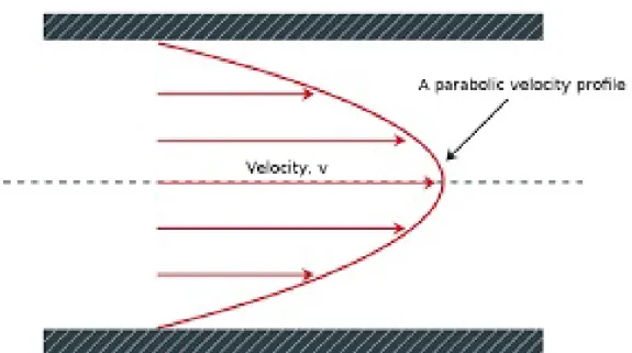
Continuous flow systems have a single fluid flowing in channels. The flow is usually driven by pressure gradient. The fully developed flow has a parabolic velocity profile with zero velocity at the walls and maximum at the center of the channel. Zero velocity at the walls is governed by no slip at walls. Due to the non uniform velocity profile there is dispersion in the channels and fluid experiences different residence time depending on the location from the center line, thereby rendering this flow type unsuitable for nanoparticle synthesis or in some cases even biological applications. Moreover the synthesized nanoparticles may stick to the walls of channels causing clogging. Figure 1.1 shows the velocity profile inside the channel.
Figure 1.1: Velocity distribution inside a channel
1.1.2 Droplet Based Flow System
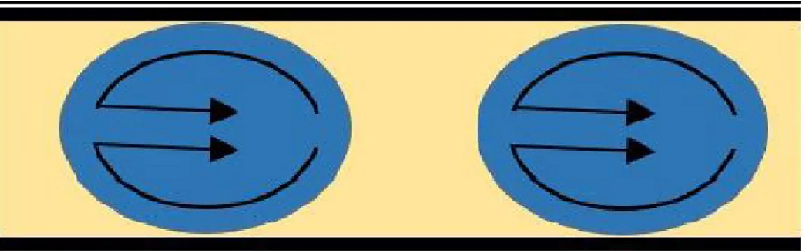
In case of a segmented flow or droplet based flow there exist two immiscible flu-ids. The fluid that wets the channel walls and carries the droplets is called as continuous phase or carrier fluid. Dispersed phase is carried in form droplets by the carrier fluid. The velocity of the droplet is uniform and there is no dis-persion so the residence time is uniform for all of them. Moreover the droplets are surrounded by the continuous flow and there is no contact with the channel walls which eliminates the clogging problem. Mixing within the droplets is also enhanced by the circulation of fluid particles in droplet as shown in figure 1.2. These all factors count to narrow size distribution as compared to continuous flow systems.
Figure 1.2: Flow profile in droplet based microfluidic reactor
T-junction and co-flowing designs are two most commonly used geometries to generate droplets. [12, 13, 14, 15, 16, 17, 18]
Droplet generation and size and spacing of droplets depends on geometry, properties of fluids and flow conditions like flow rate and flow rate ratio.
1.1.2.1 Governing parameters in droplet generation
Fluid behaviour can be explained in terms of dimensionless numbers. In the case of microfluidics Reynolds’s number is always low which means that inertial effects are less dominant and surface forces, i.e viscous forces in this case, play a vital role. Secondly the Webber number which is a ratio of inertial force to surface tension would also be very small in microfluidics. Gravitational effects are also negligible which can be explained by the Bond number being less than 1, ratio of gravitational force to surface tension. Above discussion leaves surface tension and viscous forces to be the major forces in microfluidics. Capillary number gives the ratio between these two. Capillary number is given by equation 1.1.
Ca = µU L
γ (1.1)
Where µ is the larger viscosity and γ is the the inter-facial surface tension. In case of low Ca number, surface tension forces dominate and spherical droplets are produced to minimize energy but in case of higher Ca number the viscous forces
are dominant and large deformations are observed resulting in droplets having asymmetric shapes or not forming at all
1.2 Microreactors for nanoparticle synthesis
Microreactors have been used for synthesizing nanoparticles for more than a decade now. The reason for utilizing microfluidic platform is the possibility to achieve monodisperse size distribution due to precise control over reaction condi-tions and residence time as explained earlier.
Semiconductor nanoparticles caught the attention of scientists quite early on because of their unique properties and applications. Shestopalov et al. used PDMS based device to synthesize CdS and CdS/CdSe nanoparticles using a multistep process [19]. A droplet based microreactor was used and reagents were mixed by using serpentine channels and conditions for merging of aqueous droplets were characterized using different capillary numbers. Hung et al. syn-thesized CdS nanoparticles using alternating droplet generation and controlled fusion of droplets in PDMS based microreactor and the size of nanoparticles was ranging from 4.2 nm to 8.2 nm [20]. Chan et al. developed a glass droplet based microreactor for high temperature synthesis of CdSe nanoparticles [21]. In the microreactor alternatingly formed reagents droplets were merged using nozzle geometry and later mixed in serpentine channels and resultant particles were monodisperse with average size of 3.5 nm . Yen et al. reported high temperature synthesis of CdSe quantum dots using multi zone silicon based microreactor [22]. Bio-materials have wide applications like drug delivery, biosensors, chromatog-raphy separation and information storage, due to which bio-compatible polymer nanoparticles have also been synthesized using microfluidic platforms. Sugiura et al. used a PDMS based microreactor to synthesize calcium alginate gel mi-croparticles [23]. Particles were synthesized and later combined to get composite particles in a microfluidic chip. Zhang et al. reported synthesis of bio-polymer hy-drogel particles using PDMS microreactor and by varying residence time various
shapes of hydrogel particles were obtained [24].
Song et al. reported the synthesis of paladium nanopaticles using a PEEK (polyetheretherketone) substrate [25]. Microreactor had 5 parallel reactors, each reactor containing 4 way mixers and three way reaction channels. Both batch-wise synthesis and microfluidic synthesis were performed and compared and it was concluded that nanoparticles from microreactor had narrower size distribution. Synthesis of copper nanoparticles using a similar microreactor was also reported [26]. Le et al. synthesized silver nanoparticles using a microreactor composed of micro-channels fabricated from stainless steel and immersed in oil bath for continuous and constant heating [27].
Gold nanoparticles were synthesized by J. M. Köhler using microfluidic chan-nels, using etching to produce micro channels in silicon and then bonding to pyrex glass for optical access [28]. J. M. Köhler also used microfluidic devices with channels in pyrex glass and then bonding with silicon to enclose the chan-nels [29, 30]. Both of these devices employed continuous flow and resulted in narrower size distribution as compared to conventional batch-wise synthesis. Er-dem et al. reported a multi temperature zone droplet based microreactor for synthesis of titanium dioxide nanoparticles at high temperature and synthesized titanium oxide nanoparticles at different temperatures with an average size of 26.5 nm [31].
1.3 Synthesis of Iron Oxide Nanoparticles
Synthesis of magnetic iron oxide nanoparticles has attracted a lot of attention in past because of their applications in various fields like bioimaging, [32, 33] drug delivery, [34] magnetic data storage, [35] hyperthermia, [36] and separation of biological samples [37] .
1.3.1 Batch-wise Synthesis of Iron Oxide Nanoparticles
Synthesis of iron oxide nanoparticles has been going on for a long time because of their remarkable properties and applications. The most common method for synthesizing iron oxide nanoparticles is co-precipitation. Fe(II) and Fe(III) salts are mixed in presence of a basic solution either at room temperature or at high temperature. Babes et al. used chloride salts and tetramethylammonium hydrox-ide (TMAOH) to synthesise iron oxhydrox-ide nanoparticles for MRI contrast study [38]. Park et al. used entacarbonyliron and oleic acid in different moralities to produce nanoparticles with various size ranging from 6 to 15 nm [39]. Maity et al used chloride salts and ammonium hydroxide to synthesize magnetic nanoparticles and stabilized in aqueous solution of dodecane and kerosene and also by producing a stabilizing coating using oleic acid [40].
1.3.2 Microfluidic Synthesis of Iron Oxide Nanoparticles
Synthesis of nanoparticles using microfluidic system has advantages over conven-tional techniques like monodisperse size distribution, which is why there has been a shift from conventional techniques to microfluidic systems.The reason for pre-ferring microfluidic platforms is due to their ability to control reaction conditions and residence time as stated earlier. Frenz et al. synthesized iron oxide nanopar-ticles using droplet based microfluidic reactor [41]. Droplets from Fe(II) and Fe (III) chloride solution and ammonium hydroxide solution were generated using coupled nozzles and were merged using electrocoalescence and the nanoparticles obtained had high mondispersity with average size of 4 nm. Abou Hassan et al. used chloride salt and tetramethylammonium hydroxide in co axial continuous flow microfluidic device to synthesize iron oxide nanoparticles [42]. The resultant nanoparticles were supermagnetic and average diameter was 6 nm with standard deviation of 0.2. Abou hasan et al.reported mutistep process for synthesis of iron oxide nanoparticles and then its encapsulation in silica on a single microfluidic platform with overall average size of 50nm [43].
Zhang et al. employed a two step process to synthesize and coat iron oxide nanoparticles with ZIF-8 [44]. Kumar et al. reported synthesis of magnetic iron oxide core shell nanoparticles using a droplet based microreactor and utilized the nanoparticles for MRI and found quite high saturation magnetization [45]. Recently an open microfluidic platform was also used to synthesize iron oxide nanoparticles [46]. Textured surfaces were used to move droplets of reagents using vertical vibration and then both droplet were merged at a junction and continued down the track to synthesize iron oxide nanoparticles. This method eliminates the clogging issue faced in channels.
1.4 Synthesis of Chitosan Nanoparticles
Chitosan has been recently investigated as a biopolymer to be used as gene car-rier [47] and for drug delivery. [48]
1.4.1 Batch-wise Synthesis of Chitosan Nanoparticles
Chitosan nanoparticles have been synthesized using conventional batch-wise tech-niques for quite some time now because of applications in protein, gene and drug delivery. Qi et al. prepared chitosan nanoparticles using gelation of chitosan with tripolyphosphate solution and investigated antibacterial activity of nanoparti-cles [49]. Janes et al. synthesized chitosan nanopartinanoparti-cles loaded with doxorubicin by mixing doxorubicin with chitosan solution and precipitating at pH of 5 [50].
Xu et al. synthesized chitosan nanoparticles, with diameter from 20 to 200 nm, in various formation using ionic gelation of chitosan with tripolyphosphate and investigated the effect of structure on protein delivery [51]. Katas et al. produced and used chitosan nanoparticles for gene delivery [52]. The size of nanoparticles was less than 500 nm depending on type, molecular weight as well as concentration of chitosan. Grenha et al. prepared microencapsulated chitosan nanoparticles and used for lung protein delivery. Nanoparticles were prepared
using ionotropic gelation of chitosan with tripolyphosphate (TPP) [53].
1.4.2 Microfluidic Synthesis of Chitosan Nanoparticles
The biological applications of chitosan nanoparticles require uniform size as well therefore it is very important to control the size distribution of nanoparticles. That is why there have been a shift from conventional methods to microfluidic platforms for the synthesis of chitosan nanoparticles. Majedi et al. [54] synthe-sized hydro-dynamically modified chitosan nanoparticles using continuous mi-crofluidics and showed the self assembly of chitosan particles. Flow focusing device was used to precipitate chitosan in acidic pH with basic water used as a buffer solution. Encapsulation and drug release profile of anticancer drug was also investigated. Çetin et al. reported microfluidic device for the synthesis of chitosan nanoparticles using chitosan solution in acetic and tripolyphosphate (TPP) [55]. Yang et al. used a droplet based microfluidic reactor to synthesize monodis-perse chitosan microparticles [56]. Emulsions of chitosan solutions were formed using T junction and then droplets were sorted according to their size. Larger and smaller droplets were gathered in two different reservoirs containing TPP solution where reaction took place and precipitate was collected. Lee et al. synthesized chitosan microfibers for bio-artificial liver chip [57]. A microfluidic platform was proposed to fabricate the microfibers with varying diameter and was then used for bio-artificial liver chip.
1.5 Synthesis of Composite Nanoparticles
Composite nanoparticles have attracted the attention of scientists because of their outstanding properties and applications in several fields. Another reason for exploring the synthesis of composite nanoparticles is that they show much different properties compared to plain particles [58]. Hence there is a possibility
of coming up with novel materials. Composite nanoparticles especially polymer-metal/metal oxides nanoparticles have attracted a lot of attention. Composite nanoparticles have been synthesized using batch-wise techniques for a long time but due to high monodispersity in size, control over reaction condition and resi-dence time in the microfluidic platform, there have been a shift to microreactor for composite nanoparticle synthesis. Another reason for this shift is the mul-tistep process for composite material synthesis. Conventional synthesis combine both these steps in one and thereby resulting in non homogeneous size but mi-croreactors has the ability separate these steps which results in homogeneous size [59].
Wang et al. produced ZnS-coated CdSe composite particles using a microflu-idic platform [60]. Size of nanoparticles was controlled by changing the residence time. Both precursors were mixed and heated to precipitate. Zhang et al. synthe-sized PDMS coated gold nano fibers and studied its properties and applications in protein immobilization,immunoassays and other biochemical analysis on PDMS microchips [61].Yang et al. synthesized silver-chitosan composite nanoparticles using a droplet-based microfluidic device [62]. Emulsions of solution of chitosan and silver nitrate were generated and then collected in sodium hydroxide bath and nanoparticles were collected. Antibacterial properties of these nanoparticles were studied which make them useful for potential applications such as bacteri-cidal agents for water disinfection, anti-pathogens and surface plasma resonance enhancers.
Hwang et al. used a droplet based microfluidic platform to synthesize magnetic hydrogel microparticles [63]. PDMS based device were used to generate emulsions and were exposed to UV radiation to react by UV polymerization.Valencia et al. reported a microfluidic platform with hydrodynamic flow focusing to produce lipid-polymer and lipid-quantum dots in as single step [64]. Continuous flow microfluidic platform with serpentine channels for passive mixing. Polymer core can be used for drug encapsulation and quantum dot core for imaging application and shell is made of lipid in both cases.
1.5.1 Synthesis of Composite Nanoparticles (Iron-oxide
coated with different materials)
Magnetic iron oxide nanoparticles have applications in fields like drug delivery [34], hyperthermic treatment [65], magnetic resonance imaging (MRI) [66] and selective separation of biological fluids [67]. Due to these applications iron oxide nanoparticles coated with different materials has been synthesized both using con-ventional techniques as well as microfluidic platform. In this section microfluidic synthesis will be discussed only.
Kumar et al. synthesized dextran coated super-magnetic iron oxide nanopar-ticles for MRI applications [45]. Droplet based microfluidic reactor was utilized and crystalline particles were obtained with mean diameter 3.6 nm and standard deviation 0.8 nm. Santra et al. synthesized used micro emulsions to synthesize silica coated iron oxide nanoparticles for various applications [68]. Effect of dif-ferent surfactants and basic solutions on the size and structure of nanoparticles were also investigated and the mean diameter for different conditions varied be-tween 3 and 9 nm with standard deviation of 1 to 4 nm. Abou-Hassan et al. used multi step reactor to coat iron oxide nanoparticles with silica [43]. Continuous flow microreactor was used and resultant particles had average size of 50 nm with one or more iron oxide nanoparticles in each. Rao et al. encapsulated iron oxide nanoparticles in erythrocyte using using electroporation in microfluidic device [69].
1.5.2 Synthesis of Chitosan Coated Iron oxide
Nanoparti-cles
Magnetic properties of iron oxide and bio-compatibility of chitosan can be used together for targeted drug delivery. Most of drugs used in chemotherapy are detrimental to healthy cells as well as diseased cells, thereby causing many side effects like weakness, nausea etc which are quite painful. A key solution to deal
with this problem is targeted drug delivery, where a drug carrying agent is de-livered to directly to the infected area and then releases the drug into infected cells.
Chitosan can be used in drug delivery due to its biocompatibility, low toxic-ity, biodegradability and stability. [70, 71] When it is synthesized in nanometer dimensions, due to its small size and pH responsive chemistry it can penetrate into cells to release the drug that it carries. [70]
Due to their small size, magnetic nanoparticles behave as single domain mate-rials and therefore when there is an applied external magnetic field, they behave like a paramagnet. This effect is named as ‘paramagnetism’ which means that when there is a magnetic field, nanoparticles align themselves with the applied field. In order to perform targeted drug delivery, nanoparticles should be com-posed of both a magnetic material and chitosan that carries the drug.
Chitosan coated iron oxide nanoparticles has been synthesized before using batch-wise techniques for various applications. Unsoy et al. synthesized chitosan coated iron oxide nanoparticles by co-precipitation of Fe(II) and Fe(III) with chitosan solution [72]. Safari et al. used a similar procedure to obtain chitosan decorated iron oxide particles and used as catalyst in in the synthesis of phenytoin derivatives [73]. Zarnegar et al. reported the use of composite nanoparticles as catalyst for for the synthesis of 2, 4, 5-trisubstituted imidazoles [74]. He et al. described a single step and two step process for the synthesis of chitosan decorated iron-oxide nanoparticles and reported their performance for the removal of furfural from aqueous solution [75].
Overall the remarkable properties of chitosan coated iron-oxide nanoparticles makes them very suitable for various application especially targeted drug delivery. In bio medical applications the size of nanoparticles is very important. The size of nanoparticles should be small enough to avoid any issues in circulation and should not cause pulmonary embolism. [72] Hence monodispersity in size is required in order to use all the nanoparticles.
Microfluidic platform has been quite promising in giving a narrower size dis-tribution. The reactor introduced in this thesis is the first attempt to synthesize chitosan coated iron oxide nanoparticles using a microfluidic platform to the best of our knowledge.
1.6 Thesis Overview:
In this thesis a droplet based microreactor that combines droplet generation, merging and mixing is designed and utilized to synthesize chitosan coated iron oxide nanoparticles. By this way a multi step reaction is performed in single reactor.
Chapter 2 describes the design and fabrication process for the microreactor. Detailed description of design process and optimization is given starting from preliminary design to the final design. Fabrication procedure of the devices is also described.
Chapter 3 introduces the batch wise synthesis of nanoparticles and then ex-periments regarding the microfluidic synthesis are described. Results from both type of synthesis are also presented.
Chapter 4 describes the use of the microreactor to synthesize other materials like hydroxyapatite using varying concentration of precursor solution. And a brief overview of results is presented.
Chapter 5 provides the summary and conclusion of thesis and gives recom-mendation for future work.
Chapter 2
Design and Fabrication of the
Microfluidic reactor
Continuous flow and droplet based flow systems have been used to synthesize nanoparticles as described in chapter 1. Droplet based flow systems have advan-tages over continuous flow system such as uniform residence time, no dispersion and no contact with channels walls which eliminates clogging issue. Hence a droplet based microreactor has been to synthesize composite nanoparticles. Mi-croreactor consist of three essential components integrated in single microfluidic chip, alternate droplet formation platform. merging platform and mixing plat-form. In this chapter a design and fabrication of the microreactor is presented.
2.1 Fabrication of the Microreactor
Different materials could be used to prepare microfluidic reactor. Polymers es-pecially Polydimethylsiloxane (PDMS) is most commonly used for microlfuidic reactors. One of the main reason for using PDMS is the ease of fabrication pro-cess. It is easily fabricated using conventional soft photo-lithography. They are
cost effective but have a limitations regarding operating temperature and pres-sure. As the reactions were performed at room temperature so there was no issue of temperature in this case.
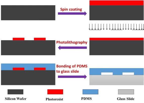
Figure 2.1 shows the fabrication steps of microreactor.
Figure 2.1: Photolithography fabrication steps for the PDMS microreactor 1) Firstly a silicon wafer is cleaned using acetone, isoproponal and water. 2) Then photo resist is coated by spin coating.
3) After the pre bake step photoresist is exposed to UV light through mask. 4) After the developement channels are formed on the silicon wafer.
5) PDMS and curing agent in the ratio of 10:1 are mixed, poured on silicon mold and cured.
channels.
Details of fabrication process and recipe can be found in Appendix A.
2.2 Design of the Microreactor
Microreactor design is an iterative process. In this section the whole process starting from initial design to the final design is presented.
2.2.1 Initial Design
Initially a simple design was proposed with three inlets for dispersed phase and one for continuous phase as presented in Figure 2.2.
Figure 2.2: Layout of the initial Design
In this design the idea was to mix and form droplets out of three reagents re-quired for the synthesis and to use olive oil as the continuous phase. A T-junction was used to form droplets and mix reagents inside the serpentine channels. After
mixing of the reagents the reaction would take place in the straight channels and nanoparticles were collected at the outlet. The channels were 100µm wide and the height was also 100µm.
Figure 2.3: 3D View of initial design
However this design had a few issues. As the pressure in rectangular channels is given by the following equation.
∆P = 12µL
W h3Q (2.1)
Where µ is viscosity, L is the length of channel and W and h are dimensions of cross section W being larger than h and Q is the flow rate. As the length of channels were about 1 m, the pressure exerted to the inlets were quite high and PDMS could not hold that much pressure there by causing the leakage. And the reaction was so vigorous that the reagents were reacting before even forming the droplet and clogging the T junction and therefore disrupting the flow as shown in Figures 2.4 and 2.5. Due to these reasons, the design of microfluidic device was modified.
Figure 2.4: T-junction clogged due to vigorous reaction
2.2.2 Initial Improvisation in Design
After considering all those factors a new design was presented. As shown in Figure 2.6 separate T junctions were introduced to generate droplets from each reagents. The length of channels were also decreased to a considerable extent there by reducing the back pressure and eliminating the back flow. The channels were 100µm wide and the height was also 100µm.
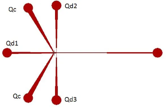
Figure 2.6: Layout of the device. Here Qc is continuous phase while Qd1, Qd2 and Qd3 are dispersed phase 1, 2 and 3 respectively
All the three dispersed phases were forming the droplets separately. Dispersed phase 2 and dispersed phase 3 were supposed to alternate in droplet formation while dispersed phase 1 droplet were to be merged with those to initiate reaction. But there was no clear pattern of alternation between droplets from dispersed phase 2 and dispersed phase 3. However underlying issue in this design was the merging of droplets. Droplets were not merging at the double T junction and hence it could not be concluded that the reaction was taking place in droplets as shown in Figure 2.7
Figure 2.7: Snapshot of experiment
2.2.3 Second Improvisation in Design
As there were two issues presented in the previous design, the following steps were taken to make sure there is an alternative droplet formation from two reagents and the droplets are merging.
2.2.3.1 Alternating Droplet Formation Geometry
Saqib et al. investigated different geometries for alternating droplet forma-tion [76]. Tapered inlet channels were used for dispersed phase and angle for taper was modified to see the effect on the efficiency of droplet formation. It was concluded that a taper angle of 25◦ was very efficient for alternating droplet
generation. Hence that geometry was employed to get alternating droplets from two reagents.
2.2.3.2 Merging of Droplets
After solving issue of alternating droplets, focus was on to find a solution to merge droplets efficiently. The concept behind this was the continuity equation.
Av = Constant (2.2)
where A is the cross section area of channels and v is the velocity of continuous phase. If area is increased the velocity will go down by same proportion. Hence by changing the width of channels, it is possible to slow down the two droplets such that they catch up on each other and merge.
A simple geometry possible was used to increase the width of channels to favour merging and then decreased the width to normal dimensions proposed and demonstrated by Bremond et al. [1] (Figure 2.8). However it is not stable for long times. Droplets may start accumulating in that region and more than two droplets may merge depending on the size of the droplets. And it will be quite difficult to make sure that only two droplets should merge and this goes on for the whole time the experiment is running.
In order to avoid accumulation of droplets in the extended section of channels, pillar induced geometry was proposed [77]. The physics behind this geometry is still the continuity equation, however pillar structures keep the droplets in straight line and avoid accumulation. The pillar structure is shown in Figure 2.9: Both alternating droplet generation platform and pillar induced geometry was combined as shown in Figure 2.10. In this device tapered inlets generate droplets alternatively which are later merged in the pillar induced geometry and a third reagent droplet is also merged in the pillar induced geometry.
The issues faced in this device were related to merging of droplets from dis-persed phase 1 with the merged droplet of disdis-persed phase 2 and 3. Apart from that some of the droplets were seen escaping through the side channels instead
Figure 2.8: Time sequence showing the destabilization of a droplet pair passing through a symmetrical coalescence chamber: collision, relaxation, separation, and fusion. Reproduced with permission [1]
investigated experimentally and the solution is provided in next section
2.2.4 Final Design
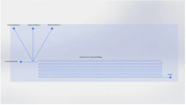
In order to overcome the problem faced in previous design, a new approach was considered. In this approach first tapered geometry was used for alternate droplet generation which are then merged using pillar induced geometry. Merged droplet will then go undergo mixing in serpentine channels and finally the third reagent will be introduced from another inlet to initiate reaction. Mixing and reaction will occur in serpentine channels and nanoparticles will be collected from outlet. The schematic is shown in Figure 2.12. And the fabricated device is shown in Figure 2.13.
Figure 2.9: 3-D model of pillar structure
Figure 2.12: Lay out of the device with alternate droplet generation and merging geometry
Figure 2.10: Layout of the device with alternating droplet generation and pillar induced merging geometry where Qc is continuous phase while Qd1, Qd2 and Qd3 are dispersed phase 1, 2 and 3 respectively
Figure 2.11: Experimental snapshot showing the droplet escaping from side chan-nels
2.2.4.1 Optimization of Pillar induced merging geometry
Pillar induced merging geometry needed to be optimized in order for merging to take place at all the time and to prevent the side flow. If a part of droplet is escaping from sides it means that the concentration of reagent has changed and the reaction will not take place if the molarity of solution is different. Hence it was essential to optimize the dimensions. Three geometries were used as shown in Figure 2.14.
Figure 2.14: Pillars induced merging geometry with different widths (a) 335µm (b) 355µm (c) 250µm
In Figure 2.14 c,the width of 250 µm and dimensions of pillars are increasing downstream by 10 µm . However this was not enough for droplets to slow down and merge so the droplets escaped without merging at all.
In Figure 2.14 b the width is 355 µm and the width of pillars in increasing by 10 µmat first then start decreasing after fourth pillar by 5 µm. The droplets were merging in this case but due to larger side channels, a segment of droplets escaped from there hence rendering this unsuitable.
In Figure 2.14 a, the width is 335 µm and the width of pillar is increased by 10 µm for first four pillars and then it increases by 5 µm. In this case two consecutive droplets merged which was the requirement. Moreover no side flow
was observed thereby making it the optimized geometry.
Figure 2.15: Layout of the device
After some experiments another change was made in the design as shown in Figure 2.15. Another T junction was introduced downstream to generate ammonia droplets separately. And the fabricated device is shown in Figure 2.16.
Chapter 3
Synthesis of Chitosan Coated
Iron Oxide Nanoparticles
Chitosan coated nanoparticles have various applications ranging from drug deliv-ery to being used as catalyst. Chitosan coated iron oxide nanoparticles have been synthesized using batch wise synthesis technique. He et al. [75] synthesized Chi-tosan coated nanoparticles by mixing chiChi-tosan solution with iron chloride solution and then adding ammonia solution drop wise to initiate reaction.
3.1 Batch-wise Synthesis of Chitosan Coated
Iron Oxide Nanoparticles
In order to optimize the recipe for microfluidic synthesis of chitosan coated iron-oxide nanoparticles batch wise synthesis was performed. Recipe reported by He et al. [75] was used.
Experiment 3.1 :
stirring for 30 minutes. 1.09g of Fe(III) chloride and 0.4g of Fe(II) chloride was dissolved in 100 mL of water. Then both solutions were mixed by magnetic stirrer for two hours at room temperature. Finally 100mL of 28% ammonia solution was added drop wise and mixture was stirred for another two hours at 95°C. After that nanoparticles were centrifuged and solvents were removed and diluted in water.
Table 3.1: Chitosan coated iron oxide nanoparticle synthesis: Batch-wise reac-tion: Experiment 3.1
Batch synthesis
Reaction Time 6 hours Average Size 7.4 ±1.5 nm Number of Measured Particles 40
(a) (b)
(c) (d)
of ammonia. Instead of 28%, it was diluted to 14% to see the effect of ammonia concentration. This was done to see if concentration changes anything in the final product as in microfluidic reactor it would be desirable to use less concentration of ammonia. Everything else was kept same as in Experiment 3.1.
Table 3.2: Chitosan coated iron oxide nanoparticle synthesis: Batch-wise reac-tion: Experiment 3.2
Batch synthesis
Reaction Time 6 hours Average Size 7.4 ±1.4 nm Number of Measured Particles 40
(a) (b)
(c) (d)
Figure 3.2: TEM images for batch-wise synthesis (Experiment 3.2)
Decreasing the concentration of ammonia did not have a major effect on the nanoparticles size. The residence time was also similar in both the cases. As
Table 3.3: EDX data Element Percentage Fe 33.13
O 66.86
ammonia is being used to change pH so that the reaction can start, hence reducing the concentration to half did not have significant effect.
3.2 Synthesis of Chitosan Coated Iron oxide
Nanoparticles Using Microreactor
Design of the microreactor has been described in detail in Chapter 2. After designing and fabrication of each microreactor, DI water and silicon oil were used to identify and optimize flow configuration. Then those flow configurations were used with chemical reagents to synthesize nanoparticles. Device layout is shown in Figure 3.3.
Figure 3.3: Layout of the device
The dimensions of main channels were 150 µm ×100 µm. Double T junction tapered inlets were used for alternating droplet generation and pillar structure was used for merging two consecutive droplets. Serpentine channels enhanced mixing by stretching and folding within a droplet.
3.2.1 Materials
For the synthesis of chitosan coated iron oxide nanoparticles in microfluidic reac-tor the recipe reported by He et al. was used [75]. Chemicals were ordered from SigmaAldrich, solutions were prepared in DI water obtained. 0.75g of chitosan was dissolved in 100 mL of 0.3% acetic acid by continuous stirring for 30 minutes. 1.09g of Fe(III) chloride and 0.4g of Fe(II) chloride was dissolved in 100 mL of water. These two solutions were used as dispersed phase 1 and 2 as shown in Figure 3.3 at tapered inlets. Initially olive oil was used as the continuous phase which was later replaced by silicon oil. Ammonia solution was used as dispersed phase 3.
3.2.2 Experimental Set-up
Experiments were performed at the microfluidics laboratory located in the Me-chanical Engineering Department. Experimental set-up is shown in Figure 3.4
As shown in Figure 3.4 all the reagents were supplied using syringe pumps. Capillary tubing were used to transport fluids from syringes to inlets. An inverted microscope was used to observe the process going on in the channels. It can be viewed and recorded using camera and computer as shown in Figure 3.4. Flow rates can be easily controlled by using syringe pumps.
Figure 3.4: Experimental set-up: Solutions are pumped by the syringe pumps through the capillary tubing. A constant monitoring of the channels is available through the microscope.
3.2.3 Experiments
After preparing devices and connecting capillary tubing for inlets, oil was intro-duced in the channels until whole device was filled with oil. During the plasma bonding process, surface is modified and it became hydrophilic. In order to make the surface hydrophobic again, it’s necessary to wet the channels with oil. This makes the surface hydrophobic again and facilitates the formation of droplets. After filling the whole device with oil, reagents are supplied and the process is observed using an optical microscope.
3.2.3.1 Alternating droplet generation
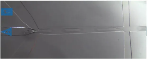
In order for the reaction to take place chitosan and iron chloride solutions need to mixed in 1:1, which implies that the size of the droplets should be identical. As described by Saqib et al. [76] tapered angle of 25°at inlets gives the highest efficiency of repetition of a pattern with uniform size and spacing of droplets. Figure 3.5 shows a sequence of droplet generation. Droplets are generated from both iron chloride solution and chitosan solution alternatively.
Figure 3.5: Alternating droplet generation using tapered inlets. Tapered geome-try controls the pressure at the junction which enables the formation of droplets in a sequence.
junction reduces and the upper stream pushes the lower stream back into side channel. This causes the upper stream to enter the main channel and a droplet from that stream is generated. This process continues and droplets of each reagent are formed alternatively.
3.2.3.2 Droplet merging
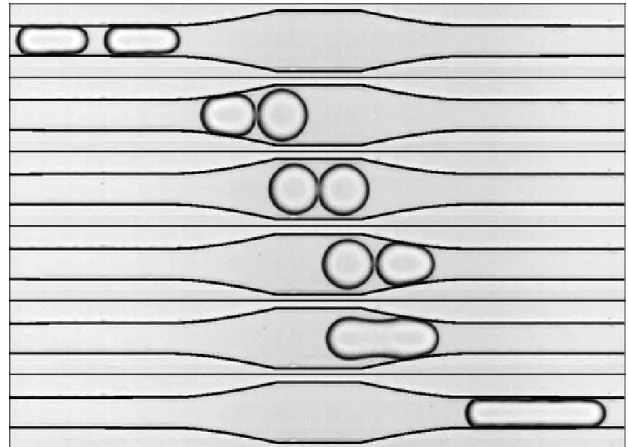
After droplet generation, one droplet of each reagent have to be merged. In order for two droplets to merge pillar induced geometry is introduced. The width of channel is extended from 150 µm to 335 µm which slows down the droplets to such extent that only two consecutive droplets are merged. Figure 3.6 shows two consecutive iron chloride and chitosan solution droplets merging in the pillar structure.
Figure 3.6: Passive merging of alternating droplets in pillar induced structure. As shown in Figure 3.6 first a droplet reaches the extended channel and almost comes to rest in pillars. Then consecutive droplet enters the channel and contacts with the droplet that is already there. These two droplets merge and then are pushed out of the pillars to enter the main channel again.
3.2.3.3 Addition of Ammonia
After merging, the resulting droplet passes through the serpentine channel where mixing of two reagents takes place. After mixing ammonia solution is added to start the reaction. Ammonia solution has been added in two ways in the experiments.
In the first method, the device shown in Figure 2.12 was used. Ammonia was added as the third dispersed phase and while entering main channel, it formed a droplet and merged with droplet containing chitosan and iron chloride.
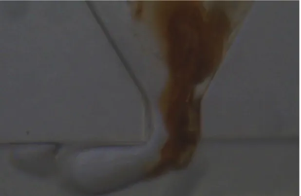
Figure 3.7: Merging of ammonia to initiate reaction
Figure 3.7 shows the merging of ammonia, the yellow colour signifies the oxi-dation of iron and is a proof of reaction taking place in droplet. But the device shown in Figure 2.12 was not promising when it comes to merging of ammonia there were minor in consistencies.
to facilitate ammonia droplet formation as shown in Figure 2.15. In this device ammonia forms a droplet at the T junction and then that droplet enters the main channel and merge with droplet to start reaction. The sequence of merging is shown in Figures 3.8 , 3.9 , 3.10 and 3.11.
Figure 3.8: Merging of ammonia droplet to initiate reaction
Figure 3.9: Merging of ammonia droplet to initiate reaction
As shown in Figures 3.8 , 3.9 , 3.10 and 3.11 ammonia droplet enters the main channel and comes in contact with already merged droplet of chitosan and iron chloride. Both droplets merge and reaction starts. Yellowish colour is due to the oxidation of iron to iron oxide and it shows the start of reaction. Then mixing takes place in serpentine channels and nanoparticles are collected at the outlet.
Figure 3.10: Merging of ammonia droplet to initiate reaction
Figure 3.11: Merging of ammonia droplet to initiate reaction
3.2.4 Results
Collected nanoparticles were centrifuged to remove solvent and then were diluted in DI water. TEM analysis was done to observe the morphology and composition of nanoparticles. FTIR data was also plotted to confirm the presence of chitosan.
3.2.4.1 TEM Results:
Nanoparticles were observed under the TEM located at National Nanotechnology Research Center (UNAM).
Table 3.4: Chitosan coated iron oxide nanoparticle synthesis: Microreactor Syn-thesis: Experiment 3.3
Microreactor synthesis
Average Size 8.5 ±1.3 nm Number of Measured Particles 40
EDX data was also collected for the samples and is shown in Table 3.5. It clearly shows the presence of iron and oxygen in nanoparticles. As the grids are made of carbon and carbon is the dominant element in chitosan, EDX result can not prove the presence of chitosan conclusively. That is why FTIR spectra was also obtained.
Table 3.5: EDX data Element Percentage Fe 44.19
(a) (b)
(c) (d)
Figure 3.12: TEM images of nanoparticles obtained by microfluidic synthesis (Experiment 3.3)
3.2.4.2 FTIR:
FTIR spectra was performed to confirm the presence of chitosan. FTIR data was plotted to compare the corresponding peaks and is presented in Figure 3.13.
Figure 3.13: FTIR spectra of nanoparticles
Chitosan presence in the nanoparticles is identified using the FTIR analysis. Successful coating of iron-oxide nanoparticles with chitosan is confirmed by the appearance of characteristic bands like OH at 3330 cm−1 and C=O at 1629 cm−1
[72]. TEM results together with FTIR demonstrate the synthesis of chitosan coated iron-oxide nanoparticles.
3.2.5 Conclusion
Following table provide a comparison between batch wise synthesis and microflu-idic synthesis.
Table 3.6: Comparison of size of nanoparticles Synthesis technique Average size Coefficient of variation
Microfluidic 8.5 ±1.3 nm 0.15 Batch 1 7.4 ±1.5 nm 0.20 batch 2 7.4 ±1.4 nm 0.18
Table 3.6 shows a comparison between size of nanoparticles among two batch wise techniques and microfluidic synthesis. It can be seen that coefficient of variation is small ac compared to batch wise techniques.
Synthesis of chitosan coated iron-oxide nanoparticles have been realized for the first time using a microfluidic platform which resulted in a narrower size distribu-tion compared to the batch-wise methods. Residence time has been significantly reduced as compared to batch-wise synthesis. Alternating droplet formation , merging and mixing was realized in single chip. Dimensions of device were op-timized and flow rate of reagents were adjusted that resulted in autonomous process from formation of droplet to the precipitation. There were a few issues like merging of ammonia droplet was not consistent all the time. Changing the continuous phase from olive oil to silicon helped in stable droplet generation from ammonia. Silicon oil was very compatible when it came to formation of ammonia droplets. However chitosan droplets formation was effected by this change, which was tackled by varying the viscosity of silicon oil. Further research can be car-ried out to find a better continuous phase which is both inert and has acceptable range of viscosity and surface tension to form droplets from all three regents and merge.
Chapter 4
Synthesis of Hydroxyapatite in
the Microreactor
Hydroxyapatite (Ca5(P O4)3OH hereafter HA) is a naturally occurring calcium
phosphate and is the mineral component of human hard tissues [78]. Therefore nanohydroxyapatite (nano-HA) has been of interest as a biomaterial for orthope-dic applications. Its outstanding properties like biocompatibility, bioactivity and osteoconductivity makes it very suitable for various applications ranging from bone tissue engineering to mineralizing agent in toothpastes to drug and gene delivery [79].
69% of the bone tissue is composed of HA which provides stiffness to bone structure and makes HA an important ceramic in orthopedic applications. Nano-HA has quicker response in implant surface turnover in implants in marrow cav-ity [80]. Muller-Mai et al. showed that nano-HA can be used for bone implants and drug release [81]. HA can be also used as a component in composite systems such as HA-chitosan-collagen [82] and collagen [83, 84, 85] for tissue engineering where HA provides stiffness and osteoconduction. Nano-HA can also be used in drug delivery systems [86, 87].
4.1 Synthesis of Hydroxyapatite
Hydroxyapatite (Ca5(P O4)3OH) is synthesized using various techniques, some of
which are:
1) Wet chemical synthesis 2) Dry chemical synthesis 3) Vapour phase reaction
Each of these methods has its own advantages and drawbacks. In case of wet chemical synthesis, water is the main by-product which is not harmful and can be easily removed from the system. Although this technique is practical and cost-effective, its very sensitive to reaction conditions. In case of dry chemical process, the reactions are easily reproducible but there is high risk of contamination [88, 89, 90].
Wet chemical synthesis is usually performed using precipitation, hydrother-mal, hydrolysis and sol-gel techniques out of which precipitation is very common. Precipitation reactions are inexpensive and produce high purity HA samples [90]. Since it is an important issue to obtain nano-HA particles with spherical shape and homogenous particle sizes, the microfluidic devices designed as part of this work was also used for the precipitation reaction.
4.1.1 Materials
Chemical precipitation uses inorganic oxide solution to form HA [91]. In this case calcium nitrate (Ca(NO3)2·4 H2O) and diammonium phosphate ((NH4)2HPO4) were used as the starting materials.
4.1.2 Microfluidic Device
PDMS based microfluidic device was used with one T junction. Fabrication procedure is same as described in Section 2.1. Figure 4.1 shows the T-junction for droplet generation using olive oil as the continuous phase.
Figure 4.1: Synthesis of Hydroxyapatite using droplet based microreactor Aqueous solutions of calcium nitrate and diammonium phosphate are used as dispersed phases and olive oil has been used as the continuous phase. Reagents make contact with each other at the junction and create an emulsion in oil. Emulsions are then transported to the outlet where nanoparticles are collected.
4.1.3 Experiments
Experimental set-up shown in 3.4 was used for this synthesis as well. Both the reagents and olive oil were introduced using syringe pumps and the droplet for-mation was observed using a microscope and a CCD camera. As shown in Figure 4.2 both reagents come in contact at the T-junction and form a single droplet.
Figure 4.2: Snapshot of droplet generation taken during experiment
Precipitation reaction takes place as reagents mix within the droplets, finally nanoparticles are collected at the outlet. Experiments were performed with vary-ing concentration of reactants.
4.1.4 Results
HA particles were observed under the SEM to find out the particle shape and size of the obtained nanoparticles.. Results from experiments with varying con-centration are presented below.
Experiment 4.1:
In this experiment 0.5 M calcium nitrate (Ca(NO3)2·4 H2O) and 0.3 M di-ammonium phosphate ((NH4)2HPO4) solution were used. Concentrations of the solutions were arranged considering the (Ca/P) molar ratio which is 1.67 for synthetic HA. Figure 4.3 shows the SEM micro-graphs for the synthesis.
(a) (b)
(c) (d)
Figure 4.3: SEM images of Hydroxyapatite (Experiment 4.1)
Reaction rate for the reactants for quite high so the reaction was taking place the immediately after the reagents come in contact with each other. Due to high reaction rate the precipitates were clogging the main channel which results in high back pressure thereby hindering the flow. Also spherical monodisperse nanoparticles were expected but SEM images shows varying size as well as the agglomeration of nanoparticles.
Experiment 4.2:
In order to reduce the rate of reaction and increase the residence time so that the reagents should react closer to outlet, the concentration of both the solu-tions were lowered but concentrasolu-tions of the solusolu-tions were arranged considering the (Ca/P) molar ratio which is 1.67 for synthetic HA. In this experiment the
concentration of calcium nitrate was decreased to 0.25 M and concentration of diammonium phosphate to 0.15 M, which is half the concentration used in ex-periment 4.1. Figure 4.4 shows SEM images for synthesis.
(a) (b)
Figure 4.4: SEM images of Hydroxyapatite (Experiment 4.2)
Reduced concentration decreased the reaction rate, however channels were still getting clogged. And the yield of reaction was decreased. Agglomeration was still an issue and the particle size and morphology was not up to expectations. As shown in SEM images particles are not spherical and vary in size.
Experiment 4.3:
This experiment was performed with much lower concentration than experi-ment 4.2. 0.125 M calcium nitrate (Ca(NO3)2·4 H2O) and 0.075 M diammonium phosphate ((NH4)2HPO4) were prepared (4 times less than the experiment 4.1). Reducing the concentration to this extent eliminated a few problems related to the clogging of the channels. Residence time increased and slow reaction prevented clogging of channels for long time. It was easier to transport the nanoparticles by the continuous phase. Figure 4.5 shows the SEM images.
(a) (b)
(c) (d)
(e) (f)
Figure 4.5: SEM images of Hydroxyapatite synthesized with lower concentration (Experiment 4.3)
Decreased concentration increased the residence time and clogging problem was solved to an extent. However after some time the clogging took place thereby
stopping the process. Nanoparticles had some agglomeration however the shape of nanoparticles were quite consistent. As the particles are not perfectly spherical but it can be seen that there is consistency in shape. However microfluidics devices was aimed to produce spherical nanoparticles with uniform size.
4.1.5 Conclusion
Synthesis of nano hydroxyapatite was realized in microfluidic device using various concentration of precursors solution. The concentration was varied and adjusted to keep constant the (Ca/P) molar ratio which is 1.67 for synthetic HA. Higher concentration of solutions resulted in clogging of channels and thereby disrupting the flow. But as the concentration was reduced the clogging was reduced but not eliminated. Shape of nanoparticles were improved with decreasing concentration however agglomeration was still a major issue. Further experiments could be performed at even lower concentration to facilitate the continuous synthesis with uniform size and shape.
Chapter 5
Conclusion and
Recommendations for Future
Work
In this thesis, a microfluidic reactor was designed and fabricated by soft-lithography. Microreactor consists of three essential components integrated in a single chip: alternating droplet formation zone, a merging zone and a mixing zone. Microreactor had precise control over reaction conditions such as mixing, reagent concentration and residence time. Optimum flow conditions were investi-gated first by using only water. Later on chitosan coated iron oxide nanoparticles were synthesized at those optimum flow conditions. The result of synthesis was quite promising and it showed narrower size distribution as compared to the batch-wise synthesis. Residence time for batch-wise synthesis was 6 hours but it takes seconds for reaction to take place in the microreactor. Moreover the amount of reagents required was quite low. Hence all these advantages make microfluidic synthesis preferable over batch-wise synthesis.
The encapsulation of iron oxide nanoparticles in chitosan has been successfully achieved with size of 8.5 ±1.3 nm, however further investigation on the synthesis of super-magnetic iron oxide is required. For instance one of the problems in
microfluidic reactor was in the merging of ammonia droplet with other reagents. The droplet merging has not been successful at all times. Hence some further improvements are required to make it consistent. Mixing in the droplets was quite successful, however sometimes precipitates stick to the channel walls causing clogging. Though it was not major problems as continuous flow usually could get rid of the clogging in no time, just slowing down the process. Therefore using solutions with lower concentrations might circumnavigate this issue. Also a pathway to encapsulate drug in nanoparticles is needed to be investigated as well as in-vivo or in-vitro experiments on drug release will help understand the efficiency of drug loading and release.
In addition to chitosan coated nanoparticles synthesis, synthesis experiments were also conducted for hydroxyapatite nanoparticle synthesis. HA is a well-known bioactive ceramic material that is used in various biomedical applications such as orthopedic, ophthalmology and dentistry. HA is the inorganic constituent of the hard tissues and can be prepared in different morphologies like granules, powders, coatings, porous blocks, etc. However, production of nano-sized HA particles have gained significant attention recently. Since conventional synthesis techniques display difficulties with obtaining particles with a distinct shape and homogeneous particle size distribution, microfluidics approach may be a promis-ing solution for this issue. Microfluidics enables to achieve spherical shaped nanoparticles with a certain particle size due to the usage of 2 same diameter channels where the precursor solutions flow. Hence, diversity in the shape and size of the nanoparticles will be reduced and the effect of the particle size and shape on the properties of the nanoparticles will be eliminated. However, troubles were faced during the experiments carried out to synthesize HA nanoparticles. Clogging was the main obstacle that stops the progress of the process. As the HA nanoparticles immediately precipitate when Ca and P solution drops react with each other and the product get stuck in the channels. Although the concentration of the Ca and P source solutions were pretty diluted and different microfluidics devices were tested, the results were not sufficient enough. Because the particle shape and size properties were not in the way that was expected. Therefore, further experiments should be realized with much more diluted solutions and/or