A Hybrid Method for 6-DOF Tracking of
MRI-Compatible Robotic Interventional Devices
A. Krieger
1,2, G. Metzger
4,5, G. Fichtinger
2,3, E. Atalar
3,6, L.L. Whitcomb
1,2Department of Mechanical Engineering
1, CISST Engineering Research Center
2, Department of Radiology
3Johns Hopkins University, Baltimore, Maryland
Philips Medical Systems, Bethesda, Maryland
4Center for Magnetic Resonance Research, University of Minnesota, Minneapolis, Minnesota
5The Department of Electrical and Electronics Engineering, Bilkent University, Ankara, Turkey
6Abstract— This paper reports a novel hybrid method of
track-ing the position and orientation of robotic medical instruments within the imaging volume of a magnetic resonance imaging (MRI) system. The method utilizes two complementary mea-surement techniques: passive MRI fiducial markers and MRI-compatible joint encoding. This paper reports an experimental evaluation of the tracking accuracy of this system. The accuracy of this system compares favorably to that of a previously reported active tracking system. Moreover, the hybrid system is quickly and easily deployed on different MRI scanner systems.
I. INTRODUCTION
The development of magnetic resonance imaging (MRI) guided robotic intervention instruments is complicated by the need to track in real-time the position and orientation of these instruments within the MRI scanner. This paper reports a novel hybrid tracking method, which utilizes two complementary measurement techniques: passive fiducial markers and MRI-compatible joint encoding. First, the locations of passive fiducial markers embedded within the instrument are obtained with a MRI scan. The initial position of the instrument is computed from these data. Second, MRI-compatible optical encoders integrated into the instrument joints are subsequently utilized to measure displacements of the instrument from its initial position. This paper reports an experimental evaluation of the tracking accuracy of this hybrid system, examining the combined effect of scanner imaging accuracy and joint encoder resolution.
A. Previously Reported Methods
A variety of methods have been developed for the spatial registration and tracking of robotic and manual instruments within MRI scanners. The principal previously reported ap-proaches are as follows:
1) Joint Encoding: Several previously reported devices
have been designed to mount rigidly on the MRI scanner, in a highly repeatable manner, in a pre-calibrated position with respect to the magnet’s coordinate system. In this approach, the position of the intervention device (e.g. needle or other surgical device) is determined by joint encoders [2], [5], [7]. This approach requires the addition of a rigid mechanical mounting system to the MRI scanner, and a precise pre-calibration of the device with respect to the scanner coordinate system.
2) Passive MRI Fiducial Features: Susil et al. developed
a passive needle guiding template for transperineal MRI-guided HDR prostate brachytherapy, where the template holes were filled with contrast material, pre-operatively localized in standard T1 or T2-weighted images, and registered to the coordinate frame of the MRI scanner [9], [10]. Beyersdorff et al. report a MRI guided transrectal needle biopsy system which employs a passive fiducial marker sleeve coaxial with the biopsy needle [1]. In this system, the needle position is manually adjusted while the passive marker is imaged with oblique T2-weighted turbo spin echo (TSE) image sequences. This approach is based on inexpensive and robust passive fiducials, but it requires repeated volume imaging of high resolution that takes considerable time to acquire.
3) Optical Position Sensing: DiMaio et al. employed an
optical tracker inside an open MRI magnet to register the end-effector of an interventional robot to the MRI coordinate system [3]. Although this approach provided real-time tracking performance suitable for visual servoing, it requires an optical tracking system to be deployed and calibrated with respect to the scanner coordinate system, requires line-of-sight between the optical tracking cameras and the device, and requires tethered light-emitting diodes (LEDs) to be attached to the instrument. The line-of-sight requirement vitiates the utility of this approach in conventional closed-bore MRI scanners.
4) Gradient Field Sensing: Hushek et al. investigated an
FDA-approved commercial tracking mechanism called En-doScout (Robin Medical Systems, Baltimore, MD) in the open MRI scanner [6]. This device offers the significant advantage that it utilizes conventional image pulse sequences and uses the gradient field for localization. In present implementations, the tracking sensors must be placed close to the MRI magnet’s isocenter, and thus may occupy critical volume in the end-effector. This approach requires a precise one time calibration procedure to be performed over the entire field of interest in each MRI system on which it is installed.
5) Micro Tracking Coils: One of the most promising
previ-ously reported tracking methods employs a number of micro-tracking coils, [8], [11], based upon an approach originally re-ported in [4]. In this approach, three (or more) micro-tracking coils are rigidly attached to an MRI-compatible instrument. A series of custom-programmed MRI pulse sequences provide one dimensional projections of the coil positions for each Proceedings of the 2006 IEEE International Conference on Robotics and Automation
Fig. 1. CAD rendering of the new MRI-guided transrectal imaging and biopsy probe incorporating a hybrid combination of passive tracking and fiber-optic joint encoders.
coil. Each individual projection pulse sequence takes several milliseconds, and the Cartesian position of all three micro-tacking coils can be completed within 50ms. The individual micro-coil position data are employed to compute the six degree-of-freedom (6-DOF) position and orientation of the instrument with respect to the scanner coordinate system. Update rates of 20 Hz for full 6-DOF tracking have been reported [8]. Experience with the micro-coil tracking method-ology reported by various authors, e.g. [4], [8], suggests the following advantages and disadvantages:
• Advantages of Micro-Coil Tracking:
1) High accuracy with mean positional errors of 0.2mm and 0.3 degrees.
2) High speed — full 6-DOF tracking update rates of 20 Hz have been reported.
3) Direct real-time 6-DOF tracking of the tool end-point.
• Disadvantages of Micro-Coil Tracking:
1) Scanner Programming: Custom tracking pulse se-quences must be developed, implemented, and tested for each scanner. These pulse sequences differ from the standard imaging pulse sequences normally available on MRI scanners. Few scanners presently support micro-coil tracking as a standard capability. In addition a custom interface between the scanner software and a tracking program must be established
to access the tracking coil locations.
2) Scanner Channel Limitations: The tracking coils re-quire a minimum of three scanner receiver channels. Most present-day MRI scanners posses four or more receiver channels, thus this method can be used on most scanners. However it limits severely the num-ber of imaging coils that can be used simultaneously for an interventional procedure.
3) Electronic Hardware: This approach requires a min-imum of three micro-coils to be incorporated within the navigated instrument, thus complicating the in-strument design and manufacturing. Moreover, the micro-coils normally require a custom-built tuning, detuning and impedance matching circuit to be developed for each scanner. Our experience with this approach is that frequent failures in the micro-coils and electrical circuit significantly degrade the reliability of the overall MRI guided instrument.
B. System Performance Goals
Our objective in the present effort was to develop an alter-native tracking methodology for a transrectal image guided prostate biopsy system. Our performance goals were the following:
1) Measure an instrument’s 6-DOF position and orienta-tion with accuracy comparable or surpassing previously reported approaches.
Fig. 2. CAD rendering of test plate. The test plate contains channels for the device axis, the needle axis and a third perpendicular channel. Markers are placed in each channel. The channels are machined with nominal angleα = 40 degrees and distance d = 50 mm.
2) Employ only standard MRI imaging pulse sequences. Do not require any custom programming of scanner sequences.
3) Employ few or no scanner receiver channels.
4) Minimize or eliminate custom programming on host MRI scanner which, in turn, will simplify the deploy-ment of the instrudeploy-ment on different scanners.
5) Employ little or no embedded electronics or antennae within the navigated instrument.
6) MRI compatibility with no imaging artifacts.
Our approach to this problem is to combine passive tracking with MRI-compatible joint encoding to provide full 6-DOF instrument tracking throughout a MRI guided interventional procedure. This paper reports the development and experi-mental performance evaluation of the hybrid fiducial tracking system for MRI-compatible instruments. The effects on overall end-effector position accuracy due to (a) fiducial MRI imaging accuracy and (b) joint encoder resolution is reported.
The remainder of this paper is organized as follows: Section II reports the hybrid 6-DOF tracking methodology. Section III-A reports the experimental methodology for evaluating the accuracy of this system. Section III-B reports the results of these accuracy studies. Section III-C compares the perfor-mance of this approach to that reported in previously published studies of micro-coil tracking. Section IV briefly summarizes and concludes.
II. 6-DOF HYBRIDTRACKING OFMRI-COMPATIBLE INSTRUMENTS
The proposed hybrid tracking method is comprised of a combination of passive tracking and joint encoders. At the beginning of an interventional procedure, the initial position of the device in scanner coordinates is obtained by segmenting fiducial markers placed on the device in MRI images. The segmentation can be done manually or automatically by the control software. From this initial position motion of the
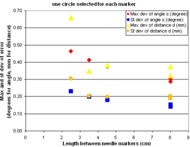
Fig. 3. Chart showing angular errors over the distance between markers. A Δe = 1
x+ c dependency seems to fit the results.
device along its degrees of freedom is encoded with either optical or manual encoders.
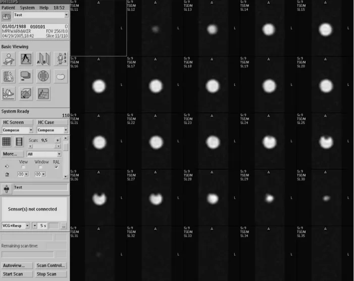
The design of a new MRI-guided transrectal imaging and biopsy probe, shown in Figure 1, employs two gadolinium fiducial marker tubes incorporated into the main axis of the device and two marker tubes placed parallel to the needle channel. Instead of acquiring axial image sets along the axes, which would take several minutes, a thin slab of 1 mm x 1 mm x 1 mm isotropic sagittal images in the plane of the markers is obtained. This reduces the imaged volume significantly and therefore reduces scan time. In order to achieve easy seg-mentation of the markers, the sagittal images are reformatted using the scanner software as axial images along the main axis of the device and along the needle axis of the device. On the reformatted axial images the tubular markers appear as circles (Figure 4), thus allowing fast and easy segmentation and definition of the center points as locations on the main axis and parallel to the needle axis respectively. The position of the two axes can then be calculated, defining the 6-DOF position of the device.
The three degrees of freedom to reach a target from this initial position are rotation of the device, change of the needle angle and insertion of the needle. Each of these degrees of freedom is encoded separately by a MRI-compatible fiber-optic joint encoder. The fiber-optical encoders interface directly to a control computer, thus eliminating any interfacing between control computer and the scanner software other than transfer-ring images. In the design depicted in Figure 1, two rotational optical encoders directly measure rotation and needle angle while the needle insertion depth is read manually using the scale on the needle. Although not present in our current design, it is possible to incorporate a translational optical encoder for the needle insertion and additional redundant encoders to provide improved error detection.
Fig. 4. Typical axial image slices of a passive fiducial marker employed in the experimental evaluation on a 3-T Phillips Intera MRI Scanner. A thin slab of isotropic 1 mm x 1 mm x 1 mm oblique sagittal PD-weighted TSE images were obtained along the axis of a tubular gadolinium marker. The sagittal images were reformatted (using the scanner’s standard software) to obtain axial images along the axis of the marker tube to facilitate identification of the marker axial centers.
III. EXPERIMENTALEVALUATION OFTRACKING ACCURACY
A. Experimental Setup
The accuracy of the passive tracking method for determining the initial device position was tested in a phantom experiment. A plate was built with three integrated channels (Figure 2): A channel representing the device axis, a channel for the needle axis at a 40 degree angle (angle α) to the device axis, and a channel perpendicular to the device axis placed 50 mm (distance d) away from the intersection point of the device and needle axis. Passive gadolinium marker tubes (Beekley Corp., Bristol, CT), 8 mm in diameter and 15 mm long were positioned along each axis. While two markers were placed in the device and perpendicular channel, the needle channel contained four markers. This setup yielded various combinations of markers with varying distances to define the needle axis. Therefore the effect of the distance between markers on the accuracy could be studied. These experiments were conducted on a 3T Philips Intera MRI scanner (Philips
Medical Systems, Best, NL).
The marker plate assembly was imaged in 16 different random orientations in the MRI scanner and the images were reformatted along each of the three channels. The scan time for the isotropic 1 mm x 1 mm x 1 mm proton density (PD) weighted TSE sagittal image sequence was 2 minutes and 30 seconds. The reformatted image sets yielded axial images along each channel with a slice thickness of 1 mm. Circles were manually fitted to each marker image and the center of the circle was recorded, if the quality of the image was satisfactory. This process yielded, depending on image quality, between 2 and 10 circle center values per marker. Low quality images were mostly due to air bubbles in the marker tubes. The three line equations for the axes were calculated from the marker center locations, using a least squares fitting algorithm based on the singular value decomposition. From the axes equations, the distance d, angle α and distance between axes were computed.
Method of axes calculations All circles for each marker used One circle per marker used Markers used to define
nee-dle channel “1, 2” “1, 3” “1, 4” “3, 4” “1,2,3,4” “1, 2” “1, 3” “1, 4” “3, 4” “1,2,3,4”
Distance between markers
(mm) 25 45 80 35 80 25 45 80 35 80
Mean angleα needle/device
axis (degree) 38.84 38.74 38.83 38.94 38.82 38.62 38.6 38.73 38.88 38.74
St dev of angle α
nee-dle/device axis (degree) 0.19 0.14 0.12 0.18 0.12 0.23 0.18 0.15 0.2 0.14
Max dev of angle α
nee-dle/device axis (degree) 0.48 0.33 0.26 0.37 0.27 0.46 0.37 0.29 0.41 0.3
Mean distance d of
intersec-tion points (mm) 51.77 51.59 51.75 51.68 51.71 51.51 51.48 51.68 51.63 51.63
St dev of distance d of
in-tersection points (mm) 0.19 0.2 0.17 0.16 0.16 0.3 0.2 0.2 0.2 0.19
Max dev of distance d of
intersection points (mm) 0.52 0.41 0.26 0.29 0.26 0.66 0.38 0.37 0.35 0.32
Mean angle perp/device axis
(degree) 89.53 89.47
St dev of angle perp/device
axis (degree) 0.26 0.25
Max dev of angle
perp/device axis (degree) 0.72 0.63
Mean distance between
nee-dle/device axis (mm) 0.29 0.13 0.11 0.08 0.09 0.2 0.13 0.1 0.1 0.09
St dev of distance between
needle/device axis (mm) 0.29 0.11 0.08 0.05 0.04 0.2 0.11 0.07 0.08 0.07
Max distance between
nee-dle/device axis (mm) 1.25 0.44 0.38 0.17 0.18 0.79 0.39 0.31 0.26 0.26
Mean distance between
perp/device axis (mm) 0.17 0.25
St dev of distance between
perp/device axis (mm) 0.09 0.09
Max distance between
perp/device axis (mm) 0.34 0.38
TABLE I
TABLE FOR ACCURACY TEST RESULTS. THE LEFT HALF OF THE TABLE PRESENTS THE RESULTS WITH ALL CIRCLES FOR EACH MARKER USED TO CALCULATE AN AXIS. THE RIGHT HALF CONTAINS ACCURACY ENTRIES WHERE ONLY ONE CIRCLE PER MARKER WAS USED TO CALCULATE AN AXIS.
THE RESULTS ARE PRESENTED IN COLUMNS BASED UPON WHICH MARKERS WERE USED TO COMPUTE THE NEEDLE AXIS.
B. Experimental Results
Table I shows the accuracy results for the 16 different orientations. On the left half of the table all recorded marker center locations were used to calculate each axis, on the right half of the table, only one center location for each marker was used. The different columns indicate which of the needle markers were combined to compute the needle axis. Highlighted are the standard and the maximum deviation for the angle α, and the distance d. The standard and maximum deviation values in the right half of the table are only slightly higher than in the left half, indicating that only one location per marker yields satisfactory accuracies, which can be achieved with a faster segmentation. Using all four markers to define the needle axis in contrast to using markers 1 and 4 only, hardly improves the accuracy results. Consequently, adding more markers within an axis does not provide considerably better accuracies.
Distance Dependency: The graph in Figure 3 plots angular
and distance errors, highlighted in Figure 3 in the right half of the table, over the distance of the markers, selected to obtain the needle axis. A theoretical model of the dependency of
the marker distance on the error was obtained. Assuming a statistical error c from determining the device axis and adding the error for the needle axis, the model yields aΔe = 1
x+ c
dependency for the error on the distance x. The experimental results, Figure 3, seem to fit this model.
C. Comparison of Micro-Coil and Passive Fiducial Tracking Accuracy
To compare the accuracy performance of the hybrid tracking method to the active tracking method, error histograms of 36 active tracking orientations and of 16 passive tracking orientations were obtained. Since the hybrid tracking method is comprised of initial passive tracking and subsequent encoder tracking, an error model for the encoders was added to the pas-sive tracking results. The optical encoders, which will be used for the tracking, have a resolution of 0.25 degrees. Therefore a random, zero mean error with uniform distribution and an amplitude of 0.25 degrees was added to the passive tracking results to simulate the combined error of the hybrid tracking method. For the passive tracking error, the marker combination 1 and 3 with one circle per marker for segmentation was
Fig. 5. Histograms for angular errors for active tracking from [8], reproduced with permission (left). Histogram for angular errors for the hybrid tracking approach (right), comprised of passive and encoder tracking. Maximum and mean error are lower for the hybrid tracking method.
selected for comparison to the active tracking. Markers 1 and 3 are located at a distance of 45 mm from each other. This distance between markers can be implemented in our device design, making this combination a logical choice.
Figure 5 shows histograms of angular errors for the active tracking (left) and the hybrid tracking (right). The accuracy results for the hybrid tracking method are very promising, considering that with a reasonable distance between markers of 45 mm, the maximum angular deviation lies at 0.6 degrees. This is below the +/- 1 degree error for the active tracking.
IV. CONCLUSION ANDACKNOWLEDGEMENTS The experimental results demonstrated that the hybrid track-ing method can be used for accurate tracktrack-ing of interventional robotic devices. Since only one location per marker is enough to accurately compute an axis, segmentation and consequent axis definition for initial position tracking can be achieved relatively quickly.
The performance of the hybrid tracking method can be summarized as follows:
• Accuracy: Tracking errors compare favorably to existing
tracking methods.
• MRI Pulse Sequences: The method uses only standard
MRI pulse sequences.
• Receiver Channels: The method does not occupy any
scanner receiver channels.
• Scanner Programming: No custom programming on the
MRI scanner is necessary, allowing the method to be employed easily in various scanners.
• MRI Compatibility: The method does not require any
electronic or metal parts on the interventional device ensuring complete MRI-compatibility and MR-safety. Active tracking methods such as micro-coils and gradient sensing remain unsurpassed in their ability to provide ex-tremely fast real-time absolute 6-DOF position measurement. The hybrid tracking method offers an alternative, providing
equivalent accuracy, real-time relative tracking, but with far greater ease of deployment on different scanners.
This work was supported in part by the NIH under Grant RO1 EB02963 and the NSF under Grant NSF ERC 9731478.
REFERENCES
[1] D. Beyersdorff, A. Winkel, B. Hamm, S. Lenk, S. A. Loening, , and M. Taupitz. MR imaging-guided prostate biopsy with a closed MR unit at 1.5T: Initial results. Radiology, 234(2):576–581, February 2005. [2] K. Chinzei, N. Hata, A. Jolesz, and R. Kikinis. Surgical assist robot for
the active navigation in the intraoperative MRI: Hardware design issues. In Proceedings of the IEEE/RSJ International Conference on Intelligent Robots, pages 727–732, 2000.
[3] S. DiMaio, S. Pieper, K. Chinzei, G. F. G, and R. Kikinis. Robot assisted percutaneous intervention in open-MRI. In 5th Interventional MRI Symposium, Boston, October15-16, Proceedings, page 155, 2004. [4] C. L. Dumoulin, S. P. Souza, and R. D. Darrow. Real-time position monitoring of invasive devices using magnetic resonance. Magn Reson Med, 29(3):411–415, March 1993.
[5] A. Felden, J. Vagner, A. Hinz, H. Fischer, S. Pfleiderer, J. Reichenbach, and W. Kaiser. ROBITOM-robot for biopsy and therapy of the mamma. Biomed Tech (Berl)., 47(Suppl 1):Pt 1:2–5, 2002.
[6] S. Hushek, B. Fetics, and R. Moser. Initial clinical experience with a passive electromagnetic 3D locator system. In 5th Interventional MRI Symposium, Boston, October15-16, Proceedings, 2004.
[7] W. Kaiser, H. Fischer, J. Vagner, and M. Selig. Robotic system for biopsy and therapy of breast lesions in a high-field whole-body magnetic resonance tomography unit. Investigative Radiology, 35(8):513–519, August 2000.
[8] A. Krieger, R. C. Susil, C. Menard, J. A. Coleman, G. Fichtinger, E. Atalar, and L. L. Whitcomb. Design of a novel MRI compatible manipulator for image guided prostate interventions. IEEE Transactions on Biomedical Engineering., 52(2):306–313, February 2005.
[9] C. Menard, R. Susil, P. Choyke, G. Gustafson, W. Kammerer, H. Ning, R. Miller, K. Ullman, N. S. Crouse, S. Smith, E. Lessard, J. Pouliot, V. Wright, E. McVeigh, C. Coleman, and K. Camphausen. MRI-guided HDR prostate brachytherapy in standard 1.5T scanner. Int J Radiat Oncol Biol Phys., 59(5):1414–23, August 2004.
[10] R. Susil, K. Camphausen, P. Choyke, E. McVeigh, G. G. GS, H. Ning, R. Miller, E. Atalar, C. Coleman, and C. Menard. System for prostate brachytherapy and biopsy in a standard 1.5T MRI scanner. Magn Reson Med., 52(3):683–7, September 2004.
[11] R. C. Susil, A. Krieger, J. A. Derbyshire, A. Tanacs, L. L. Whitcomb, G. Fichtinger, and E. Atalar. System for MR image-guided prostate interventions: Canine study. Radiology, 228(3):886–894, September 2003.