CIRCULARLY CONFIGURED MULTI-SLM HOLOGRAPHIC DISPLAY SYSTEM
Fahri Yaras¸, Hoonjong Kang, Levent Onural
Department of Electrical and Electronics Engineering, Bilkent University, TR-06800 Ankara, Turkey
[email protected], [email protected], [email protected]
ABSTRACT
The designed circular holographic display system produces ghost-like 3D optical reconstructions of a computer generated 3D model. System uses six phase-only reflective-type spatial light modulators (SLMs) that are configured circularly. Alignment of the SLMs are successful and gap problem is solved by using half-mirrors. The total number of pixels of the resultant display is11520 × 1080. Re-constructions show that increase in the viewing angle is significant compared to the single SLM case. With the help of the proposed system, observer can see the reconstructions binocularly. As a re-sult, comfortable 3D perception is achieved. In order to avoid eye-hazard, LED illumination is also used as an alternative light source. Experimental results are satisfactory. Proposed system can be used as a holographic display system.
Index Terms— holographic displays, spatial light modulators,
phase holograms, three-dimensional displays, computer generated holography, holographic 3DTV
1. INTRODUCTION
Holographic displays are one of the candidate systems for future 3DTV applications. Since holography can reproduce volume fill-ing light fields, it is a convenient technique to optically duplicate 3D objects. Those ghost-like images can be seen without any optical aid. There is no need for special glasses or eye-tracking systems. In addition, since holography regenerates optical duplicates of the 3D objects, observers do not feel motion sickness or headaches as in most of the stereoscopic displays.
Electro-holographic displays are reported in the literature. [1, 2, 3, 4, 5, 6, 7, 8, 9, 10]. There are several pixelated devices which are suitable for digital holographic display systems. Liquid crystal (LC) displays, liquid crystal on silicon (LCoS) displays, digital micro-mirror devices are a few of them. Since all those pixelated devices modulate the incoming light in the spatial domain, either transmis-sively or reflectively, they are called spatial light modulators (SLMs). Full complex modulators would be the ultimate solution; however, most of the spatial light modulators usually modulate only the am-plitude or the phase of the incident light. In our holographic display prototypes we use phase-only LCoS SLMs.
Although those SLMs are easy to use, have high diffraction ef-ficiency and are rich in term of pixel count, they are quite small in size. Typical phase-only SLM size is approximately 1cm× 2cm. As a result of it, reconstructions are also quite small. It is almost impossible to see the reconstructions binocularly and rotate around them when only one such SLM is used. Therefore researchers are trying to come up with ideas to overcome this bottleneck. Maeno et al. proposed a method to increase the size of the holographic display
978-1-61284-162-5/11/$26.00 c⃝ 2011 IEEE
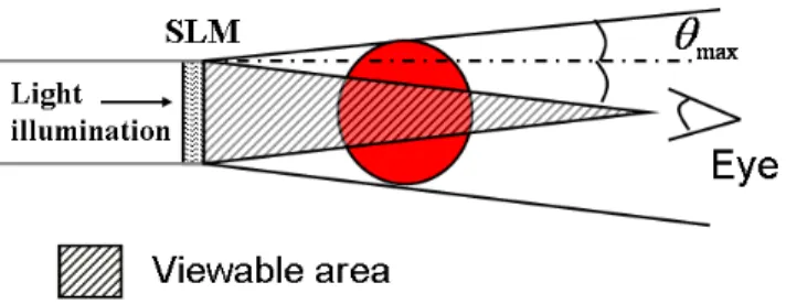
Fig. 1. Illustration of larger object reconstruction with a single SLM.
Fig. 2. Illustration of larger object reconstruction with multiple
SLMs.
system and also the field of view [11]. In their system they use five transmissive type SLMs and place them side by side. They increase the field of view along the horizontal direction, but they discard the vertical parallax by using a lenticular sheet. Yet another holographic display system is reported by Hahn et al. and they use mirror mod-ules and other optical components to increase the size of the dis-play system [12]. Their horizontal parallax only (HPO) curved holo-graphic display system provides approximately23∘viewing angle. A company from Germany, called SeeReal Technologies, developed a novel technique [13, 14, 15, 16, 17]. With the help of the tech-nique, only a part of the wavefront that enters to the eye pupil of the observer is reconstructed.
Different from the above systems, we propose to build a full-parallax circularly configured multi-SLM holographic display sys-tem. We use six phase-only reflective type spatial light modulators to increase the horizontal size of the holographic display. With the help of the proposed system, observers can see ghost-like 3D images floating in the space binocularly with naked eye. Methods and con-figurations for enlargement of the viewing angle will be presented in the following section. Section 3 presents the optical setup and holo-gram generation algorithm. Experimental results will be presented in Section 4. Conclusions will be drawn in the last section.
16 mm when mount is used 16.6 mm SLM 1 SLM 2
mount
mount
Active Area 16 mm when mount is used 16.6 mm SLM 1 SLM 2mount
mount
Active AreaFig. 3. Gap between two SLMs when they are aligned side by side
Fig. 4. Alignment of three SLMs to have a continuous array without
any gap
2. ENLARGEMENT OF THE VIEWING ANGLE
For the pixelated devices, local maximum diffraction angle for Shan-non (low-pass filter) recovery case can be calculated as:
𝜃𝑚𝑎𝑥= sin−1(𝜆𝑓𝑚𝑎𝑥), (1) where;
𝑓𝑚𝑎𝑥= 12Δ
𝑝. (2)
HereΔ𝑝denotes the pixel period of the device,𝜆 is the wavelength of the incident light. Within the limit of the local maximum fre-quency, we can reconstruct 3D objects larger than the SLM size [3]. Those reconstructions can be seen on a diffuser or a screen. How-ever, in order to see the full reconstruction by naked eye, 3D object should be in the viewable area (See Fig. 1). Otherwise observer can only see a part of it. One way to solve this problem is to increase the hologram size (See Fig. 2). Since viewable area is increased, observer can see larger reconstructions.
However, since SLMs have hard mount around it, when we place them side by side a large gap occurs between two SLMs (See Fig. 3). There are methods to overcome this problem, such as using mirror modules as in [12]. In our system, we propose to use multiple beam
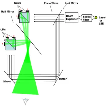
Fig. 5. Schematic of the setup
splitters (half-mirrors). As seen in Fig. 4, with the help of the beam-splitters, the gap between two SLMs are filled by the image of the third SLM. The same configuration is applied to other three SLMs and finally, these two sets are combined with a large beam-splitter (See Fig. 5). Therefore the resultant hologram size increases six times along the horizontal direction. This gives a freedom to the observer to see the reconstructions binocularly and to rotate within the limit of the viewing angle. Fig. 5 also shows the increase in the viewing angle. This enlargement is illustrated by the shaded area at the observer side. Observer can move around the holographic recon-struction in this shaded area without experiencing any discontinuity in the reconstruction.
3. OPTICAL SETUP AND HOLOGRAM GENERATION
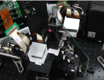
Schematic of the setup can be seen in Fig. 5. The method to obtain a larger hologram size along the horizontal direction is described in the previous section. After aligning the six SLMs side by side, we rotate the SLMs with the help of high precision stages to configure them circularly. Each SLM is rotated by1∘with respect to the next SLM (this can be increased up to3∘). Fine adjustments are also needed after the rotations. Adjustments are crucial. First, centers of all SLMs should be on the same curve and there should not be any gap between the SLMs. Second, holographic reconstructions should be aligned. In order to be sure that the alignments of the recon-structions are satisfactory we load a hologram of a single point to all SLMs. The reconstruction distance of the point has to be chosen to be the same with the desired distance of the holographic reconstruc-tion (the reconstrucreconstruc-tion distance is400𝑚𝑚 in our experiments). If reconstructions from all SLMs overlap at the same location in space, alignment procedure is satisfactory. Fig. 6 shows the front view of the holographic display system. Continuous array of SLMs can be seen in the figure. Note that the numbers on the SLMs in Fig. 6 are chosen to refer the SLMs in Fig. 5.
In our experiments, we have used computer generated 3D model of a cube (See Fig. 7). It is a wire-frame object. The model consists
Fig. 6. Front view of the display
of a point cloud. Each point in the point cloud has 3D coordinate and intensity information. Holograms are calculated by using Rayleigh-Sommerfeld light propagation algorithm [18]. Each point of the 3D model propagated to the hologram plane. Then, contributions of all the points in the point cloud are superposed to obtain complex field at the hologram plane. Since our SLMs are phase-only, we discard the amplitude and set to unity (plane wave illumination). Although discarding the amplitude lowers the quality, degradations in recon-structions are acceptable. By applying the same procedure, six holo-grams are calculated one by one, by simply rotating the 3D object by the corresponding angle. The rotation angles are−2.5∘,−1.5∘, −0.5∘,+0.5∘,+1.5∘and+2.5∘.
Top view of the setup can be seen in Fig. 8. There are two sets of Holoeye SLM modules [19]. Each SLM module has three phase-only SLMs with1920 × 1080 pixels each. SLMs in one module are aligned side by side by using non-polarized cubic beam-splitters as described in the previous section (also see Fig. 4. The resultant two sets of wide displays (total of5760 × 1080 pixels each) are also combined by a plate beam-splitter (half-mirror) to obtain a grand total of11520 × 1080 pixels wide holographic display system. All alignments are done with the help of high precision stages.
Fig. 7. Computer generated wire-frame 3D model of a cube.
Fig. 8. Top view of the display
4. EXPERIMENTAL RESULTS
Fig. 9 shows the optical reconstruction of 3D wire-frame model of a cube. Pictures are taken from different viewing angles (left, cen-ter and right). Reconstructions are captured when laser is used as a light source. In order to avoid eye-hazard [20], LED illumination is also used as an alternative source and such reconstructions are ob-served with naked eye. In addition, since the holographic display is wide in horizontal direction, reconstructions are observed binoc-ularly. Binocular observation increases the 3D perception signifi-cantly. Reconstruction distance is approximately400𝑚𝑚. We ob-served that the total field of view increased significantly compared to the single SLM case. The total field of view is approximately6∘. It can be increased up to18∘if we increase the rotation angle between SLMs to3∘. With the help of the same configuration, we can fur-ther increase the field of view and thus viewing angle by using larger number of SLMs and larger beam-splitters.
5. CONCLUSION
The proposed system has six phase-only spatial light modulators that are aligned side by side to obtain a11520 × 1080 pixel wide circu-lar holographic display system. All alignments are accomplished by the help of high precision stages. System works both with laser and LED illumination. Optical reconstructions show that increase in the viewing angle is significant compared to the single SLM case. We conclude that circular configuration is superior than the previous planar configurations. We also notice the parallax with the help of the optical reconstructions. Experimental results are satisfactory and
Fig. 9. Optical reconstruction of 3D wire-frame model of a cube. (a)
they show that circularly holographic display system works success-fully.
6. ACKNOWLEDGMENTS
This work is supported by EC within FP7 under Grant 216105 with the acronym Real 3D.
7. REFERENCES
[1] M. Kovachev, R. Ilieva, P. Benzie, G. B. Esmer, L. Onural, J. Watson, and T. Reyhan, “Holographic 3DTV displays us-ing spatial light modulators,” in Three-Dimensional Television - Capture, Transmission, Display, chapter 15, pp. 529–555. Springer, 2008.
[2] F. Yaras¸, H. Kang, and L. Onural, “Real-time phase-only color holographic video display system using led illumination,” Appl. Opt., vol. 48, no. 34, pp. H48–H53, 2009.
[3] F. Yaras¸, M. Kovachev, R. Ilieva, M. Agour, and L. Onural, “Holographic reconstructions using phase-only spatial light modulators,” in 3DTV Conference: The True Vision - Capture, Transmission and Display of 3D Video, IEEE, 2008.
[4] F. Yaras¸ and L. Onural, “Color holographic reconstruction us-ing multiple SLMs and LED illumination,” in Proc. SPIE., 2009, vol. 7237, p. 72370O.
[5] F. Yaras¸, H. Kang, and L. Onural, “Real-time color holographic video display system,” in 3DTV Conference: The True Vision -Capture, Transmission and Display of 3D Video, IEEE, 2009. [6] F. Yaras¸, H. Kang, and L. Onural, “Real-time multiple SLM
color holographic display using multiple GPU acceleration,” in Digital Holography and Three-Dimensional Imaging. 2009, p. DWA4, Optical Society of America.
[7] H. Kang, F. Yaras¸, and L. Onural, “Graphics processing unit accelerated computation of digital holograms,” Appl. Opt., vol. 48, no. 34, pp. H137–H143, 2009.
[8] H. Kang, F.Yaras¸, L. Onural, and H. Yoshikawa, “Real-time fringe pattern generation with high quality,” in Digital Holog-raphy and Three-Dimensional Imaging. 2009, p. DTuB7, Op-tical Society of America.
[9] H. Kang, F. Yaras¸, and L. Onural, “Quality comparison and acceleration for digital hologram generation method based on segmentation,” in 3DTV Conference: The True Vision - Cap-ture, Transmission and Display of 3D Video, IEEE, 2009. [10] F. Yaras¸, H. Kang, and L. Onural, “Multi-SLM holographic
display system with planar configuration,” in 3DTV Confer-ence: The True Vision - Capture, Transmission and Display of 3D Video, IEEE, 2010.
[11] K. Maeno, N. Fukaya, O. Nishikawa, and T. Honda, “Electro-holographic display using 15-megapixel LCD,” in Proc. SPIE, Practical Holography X, 1996, vol. 2652, pp. 15–23.
[12] J. Hahn, H. Kim, Y. Lim, G. Park, and B. Lee, “Wide viewing angle dynamic holographic stereogram with a curved array of spatial light modulators,” Opt. Express, vol. 16, no. 16, pp. 12372–12386, 2008.
[13] S. Reichelt, R. Haussler, N. Leister, G. Futterer, and A. Schw-erdtner, “Large holographic 3D displays for tomorrows TV and monitors - solutions, challenges, and prospects,” IEEE Lasers and Electro-Optics Society, 2008. LEOS 2008. 21st An-nual Meeting of the, pp. 194–195, 2008.
[14] R. H¨aussler, A. Schwerdtner, and N. Leister, “Large holo-graphic displays as an alternative to stereoscopic displays,” 2008, vol. 6803, p. 68030M, SPIE.
[15] S. Reichelt, H. Sahm, N. Leister, and A. Schwerdtner, “Capa-bilities of diffractive optical elements for real-time holographic displays,” 2008, vol. 6912 of Proc. of SPIE, p. 69120P. [16] A. Schwerdtner, R. H¨aussler, and N. Leister, “Large
holo-graphic displays for real-time applications,” 2008, vol. 6912 of SPIE, p. 69120T.
[17] N. Leister, A. Schwerdtner, G. F¨utterer, S. Buschbeck, J.-C. Olaya, and S. Flon, “Full-color interactive holographic pro-jection system for large 3D scene reconstruction,” 2008, vol. 6911, p. 69110V, SPIE.
[18] J. W. Goodman, Introduction to Fourier Optics, McGraw-Hill Companies, Inc., New York, second edition, 1996.
[19] S. Osten, S. Krger, and A. Steinhoff, “Spatial light modulators based on reflective micro-displays,” Technishes Messen, vol. 73, pp. 149–156, 2006.
[20] Y. Barkana and M. Belkin, “Laser eye injuries,” Survey of Ophthalmology, vol. 44, no. 6, pp. 459 – 478, 2000.