A THESIS
SUBMITTED TO THE DEPARTMENT OF COMPUTER ENGINEERING
AND THE INSTITUTE OF ENGINEERING AND SCIENCE OF B˙ILKENT UNIVERSITY
IN PARTIAL FULFILLMENT OF THE REQUIREMENTS FOR THE DEGREE OF
MASTER OF SCIENCE
By
Rıfat Aras
June, 2008
Prof. Dr. B¨ulent ¨Ozg¨u¸c (Supervisor)
I certify that I have read this thesis and that in my opinion it is fully adequate, in scope and in quality, as a thesis for the degree of Master of Science.
Asst. Prof. Dr. Tolga C¸ apın (Co-Supervisor)
I certify that I have read this thesis and that in my opinion it is fully adequate, in scope and in quality, as a thesis for the degree of Master of Science.
Assoc. Prof. Dr. Veysi ˙I¸sler
I certify that I have read this thesis and that in my opinion it is fully adequate, in scope and in quality, as a thesis for the degree of Master of Science.
Asst. Prof. Dr. H. Murat Karam¨uft¨uo˘glu
I certify that I have read this thesis and that in my opinion it is fully adequate, in scope and in quality, as a thesis for the degree of Master of Science.
Prof. Dr. ¨Ozg¨ur Ulusoy
Approved for the Institute of Engineering and Science:
Prof. Dr. Mehmet Baray
MODELING AND DYNAMIC SIMULATIONS
Rıfat Aras
M.S. in Computer Engineering Supervisors: Prof. Dr. B¨ulent ¨Ozg¨u¸c and
Asst. Prof. Dr. Tolga C¸ apın June, 2008
Hair has been an active research area in computer graphics society for over a decade. Different approaches have been proposed for different aspects of hair research such as modeling, simulating, animating and rendering. In this thesis, we introduce a sketch-based tool making use of direct manipulation interfaces to create hair models and furthermore simulate the created hair models under physically based constraints in real-time. Throughout the thesis, the created tool will be analyzed with respect to different aspects of the problem such as hair modeling, hair simulation, hair sketching and hair rendering.
Keywords: hair simulation,sketching,direct manipulation interface. iv
MODELLEMES˙I VE D˙INAM˙IK S˙IM ¨
ULASYONLAR
Rıfat Aras
Bilgisayar M¨uhendisli˘gi, Y¨uksek Lisans Tez Y¨oneticileri: Prof. Dr. B¨ulent ¨Ozg¨u¸c ve
Asst. Prof. Dr. Tolga C¸ apın Haziran, 2008
Sa¸c, 15 yıldan fazladır bilgisayar grafi˘gi toplumu i¸cin aktif bir ara¸stırma alanı olmu¸stur. Ge¸cmi¸ste, sa¸cın modelleme, sim¨ulasyon, animasyon ve g¨or¨unt¨uleme bakı¸s a¸cılarından bir¸cok farklı yakla¸sımlar ara¸stırılmı¸s ve ¨onerilmi¸stir. Bu tezde, sa¸c modelleri ¨uretmek ve bu ¨uretilen modelleri fiziksel ¸sartlar altında ger¸cek za-manlı olarak sim¨ule etmek i¸cin geli¸stirdi˘gimiz, ¸cizim bazlı do˘grudan etkile¸sim aray¨uz¨u kullanılan aracı sunuyoruz. Geli¸stirilen ara¸c tez i¸cerisinde, problemin sa¸c modelleme, sa¸c sim¨ulasyonu, sa¸c ¸cizimi ve sa¸c g¨or¨unt¨ulenmesi gibi y¨onleriyle incelenecektir.
Anahtar s¨ozc¨ukler : sa¸c sim¨ulasyonu,¸cizim,do˘grudan etkile¸sim aray¨uz¨u. v
I would like to express my thanks and gratitude to Prof. Dr. B¨ulent ¨Ozg¨u¸c and Asst. Prof. Dr. Tolga C¸ apın. Their invaluable support was always with me.
I also would like to thank Assoc. Prof. Dr. Veysi ˙I¸sler, Asst. Prof. Dr. H. Murat Karam¨uft¨uo˘glu, and Prof. Dr. ¨Ozg¨ur Ulusoy, who was kind enough to read my thesis.
1 Introduction 1
1.1 Motivation . . . 1
1.2 Organization of the Thesis . . . 2
2 Previous Work 3 2.1 Hair Modeling . . . 3
2.2 Physically Based Hair Simulation . . . 5
2.3 Hair Rendering . . . 6 2.4 Sketch-Based Interfaces . . . 7 3 Hair Modeling 10 3.1 Strands . . . 10 3.2 Wisps . . . 11 3.3 Patch Structure . . . 12 4 Hair Simulation 16 vii
4.1 Dynamics Model . . . 16
4.2 Dynamics Simulation . . . 17
4.2.1 Numerical Integration Methods . . . 17
4.2.2 Physical Simulation Step . . . 19
4.3 Collision Detection . . . 20
4.3.1 Collision Detection Structures . . . 20
4.3.2 Collision Detection-Response Step . . . 21
5 Hair Sketching 24 5.1 Mapping From 2D to 3D . . . 24
5.2 Skeleton Strand Root Positioning . . . 24
5.3 Skeleton Strand Control Point Position Recording . . . 25
5.4 Gesture Recognition . . . 27
5.5 Style Recording . . . 28
5.6 Wisp Formation . . . 29
6 Hair Rendering 34 6.1 Catmull-Rom Spline Generation with GPU . . . 35
6.2 Kajiya-Kay Lighting Model . . . 37
7 Results 42 7.1 Performance Results . . . 42
7.2 Visual Results . . . 43
8 Conclusion 46
A Hair Modeling and Physical Simulation Workflow 52 A.1 Hair Modeling Screen . . . 52 A.2 Physical Simulation Screen . . . 53
2.1 Bando et al.’s rendering technique. a) The alpha map applied to the textures, b,c) The alpha map applied to the hair texture is translated to the hair particle location and scaled in the hair direction. . . 6 2.2 The hair fiber model used by Marschner. . . 7 2.3 The precalculated Marschner terms stored as textures. . . 8
3.1 The control points are recorded as control points of the skeleton strand. . . 11 3.2 The effects of wisp style parameters on overall wisp shape. a)
constant wisp closeness, b) increasing wisp closeness, c) decreas-ing wisp closeness, and d) wisp under the effect of wisp fuzziness parameter. . . 12 3.3 The difference between a) a Bezier patch and b) a Catmull-Rom
patch with same control points. . . 13 3.4 Extrapolation of additional control points from the original control
points. . . 14 3.5 The used head model and the corresponding patch structure. . . 14 3.6 The color values are mapped to the u-v values of the patch. . . . 15
4.1 Physical model decomposition. a) The skeleton strand to be de-composed, b) the detail (yellow rods) and physical (red rods) rep-resentatives extracted from the skeleton strand, c) the generated wisp. . . 18 4.2 The drawn wind stroke and the produced wind force affecting the
hair simulation. . . 20 4.3 The used head model and the corresponding combination of
colli-sion spheres for hair-head collicolli-sion detection. . . 21 4.4 a) A skeleton strand that has increasing wisp closeness style
pa-rameter, b) the resultant wisp, c) wisp collision spheres located at skeleton strand control points scaled according to wisp closeness style parameter, d) final wisp with located collision spheres. . . . 22 4.5 Wisp and head collision spheres and extracted collision
informa-tion. . . 23
5.1 The skeleton strand that is sketched as a combination of loops. . 28 5.2 The process to solve a) ill defined skeleton strand sketches; b) the
loops, loop directions and loop focal points are detected, c) by placing axis of rotation to focal points, the control points forming the loops are mapped to helical structures. . . 30 5.3 The effects of the styling parameters: a) Constant closeness
pa-rameter, b) increasing closeness papa-rameter, c) decreasing closeness parameter, d) the fuzziness parameter in effect. . . 31 5.4 The Archimedes’ spiral on the Catmull-Rom patch u-v space. The
points are obtained with 30 degree increments. The left hand spi-ral’s closeness parameter ci,j is greater than the right hand spiral’s
5.5 The blue vector represents the offset distance for that control point. According to the fuzziness parameter, the corresponding control point of the imitator strand is perturbed by randomly replacing it in the volumes defined by perturbation spheres. As fuzziness increases, the control point is randomized in a bigger perturbation
sphere. . . 33
6.1 With the given control points C0,C1,C2,C3, a spline from C1 to C2 is obtained. . . 35
6.2 The extrapolation process of the additional Catmull-Rom spline control points. . . 36
6.3 The grouping process of the control points. . . 40
6.4 Mapping of dummy vertices to produce Catmull-Rom spline. . . 41
7.1 A wavy hair model created in our tool. . . 43
7.2 The created hair model is under the effect of wind force. . . 44
7.3 Front view of a created hair model. . . 44
7.4 A punk hair model. . . 45
7.5 Another punk hair model created by a first time user in 3 minutes 30 seconds. . . 45
A.1 The empty head model. . . 53
A.2 From left-to-right, quickly sketched skeleton strand, normally sketched skeleton strand, and slowly sketched skeleton strand. . . 54
A.4 The drawn wind stroke and the produced wind force affecting the hair simulation. . . 55
7.1 The performance of the tool under different wisp and strand num-bers. . . 42
B.1 The task list determined for the testing. . . 56 B.2 The general test profile extracted from one day long test sequence. 57
Introduction
Hair modeling and animation has been a research topic in the computer graphics field for more than 15 years. As being one of the hardest part of the character animation, hair is also one of the most important elements for producing realistic virtual humans. To produce usable tools based on hair modeling techniques, in-tuitive user interfaces should be provided to the end users, who will create the 3D content. In this aspect, the term direct manipulation interfaces becomes relevant. Direct manipulation interfaces, “which were introduced by Ben Schneiderman in 1983 within the context of office applications” [1], have started to be used within the computer graphics context recently. The techniques described in this thesis belong to direct manipulation category.
1.1
Motivation
In this thesis, our motivation is to implement a sketch-based tool, with which a user can create hair models, including the stylistic properties of hair, intuitively with a direct manipulation interface. Furthermore, our goal is to allow users to quickly create realistic physically-based animations with minimum user interven-tion. To perform the hair model and physically based animation creation steps in real-time interactively, we use the power of GPU programming techniques.
Our main design principle is that the created hair model should be subject to no extra mapping process or database lookups, to ensure that the created hair model looks and behaves as closely as possible to the sketched one. We divided this problem into four aspects: hair modeling, hair sketching, hair simulation, and hair rendering.
1.2
Organization of the Thesis
The organization of this thesis is as follows. Chapter 2 presents the previous work in the field from different aspects of the problem. In Chapter 3, the hair model used in this work (strand-wisp hierarchy) and solution to the hair loca-tion problem (Catmull-Rom patches) are explained. Chapter 4 describes the physically-based animation techniques used in the work, such as the dynamics model and collision detection method. In Chapter 5, the direct manipulation interface used to create hair models and the algorithms behind this interface are described. The GPU programming techniques used for Catmull-Rom spline gen-eration and rendering the created hair models with Kajiya-Kay lighting model are discussed in Chapter 6. Finally in Chapter 7, the experimental results of this work are presented for evaluating the performance and visual results of the tool. In the Appendix section, a user manual is supplied to help to perform tasks like creating a hair model and controlling a physically based simulation. A usability test that is performed with six testers is also provided in the Appendix section.
Previous Work
Our work spans four different aspects of the hair sketching problem: determin-ing a model to represent hair, simulatdetermin-ing the hair under physical constraints, rendering the hair in a visually appealing way, and finally performing all these tasks intuitively with a direct manipulation interface. Therefore, we examine the previous studies relevant to our work, divided with respect to these different aspects.
2.1
Hair Modeling
Different usage areas of hair models in the 3D animation/simulation context have led researchers to study different hair modeling approaches. Representation of hair as polygons to be used in game engines, individual hair strand based rep-resentation for photo-realistic rendering or particle/volume based reprep-resentation for controlling the shape of the hair are all examples of these different approaches. Choe et al. [3] present a wisp-based technique that produces static hairstyles by employing wisp parameters such as length distribution, deviation radius function and strand-shape fuzziness value. On top of this statistical model, a constraint-based styler is used to model artificial features such as hairpins. This
styler relies on three types of constraints - point constraint, trajectory constraint, and direction constraint - to create the artificial hairstyles. Gravity and the force fields formed with the constraint-based styler are used to deal with solving the hair deformation. Although the generated styles are realistic, real-time oper-ation is unavailable due to excessive calculoper-ations. In Kim and Neumann’s [4] Multiresolution Hair Modeling system, hair is implemented with a level-of-detail approach. The detail levels can vary from the whole hair model to individual hair strands. The main data structures to represent the hair at different detail levels are the generalized cylinders. In this work, generalized cylinders are ob-tained by combining skeleton curves and contour functions. Finally, scaling and twisting operations are applied for the final generalized cylinder shape. A tensor product Catmull-Rom spline patch is used to locate the hair strands. Hairstyles can be edited with low-level tools that manipulate control points such as mov-ing, scalmov-ing, or twisting the region around the chosen control point. Bando et al. [5] present a different approach to hair modeling. In their work, the hair is modeled as a set of dynamically interacting particles forming the volume of the hair. Instead of linking the particles with tight structures, they use loose connections to make the hair possible to be dynamically split and merged during its lateral motion. Koh and Huang [6] present a model to animate hair modeled in 2D parametric surfaces in real-time. A number of hair strands are grouped to form the parametric surfaces. Because the number of control points required to represent a parametric surface is much smaller than that of the required triangle vertices, Koh and Huang are able to achieve real-time animation. Daldegan et al. [26] handle the hairstyling operations by employing hairstyle parameters per head-scalp polygon. Some example parameters are material identifier for hairs on polygon, tangent vector of the hair, random angle variation applied to the tangent, and hair density value. In this work, a parametric surface is not used as a place holder. Therefore, head-scalp polygons can contain only one type of hair strand. Also hair strands can be edited with low-level operations such as control point relocation, addition or deletion.
2.2
Physically Based Hair Simulation
In Bando et al.’s work [5], the hair volume, formed by particles, is considered as a deformable body that has large tensile stiffness and small bending stiffness. The neighboring particles are connected with damped springs. These connections are made loose to realize free lateral motion of the hair. The following spring coefficient is used for these loose connections:
kij = cijW (|xij|, h1) (2.1)
Where h1 is equal to neighbor search smoothing length, and i, j are particle
indices. This spring coefficient decreases as the two particles draw apart and when they are at a distance of 2h1, it becomes zero. Oshita presents a physically-based
dynamic wisp model [7] that supports hair dynamics in a coarse model and then extends it to a fine model. Each hair strand is modeled as a serial link of particles on GPU. Verlet numerical integration technique is used because of its stable nature. With the verlet integration, it is possible to find the next position of a particle without storing the particle velocities explicitly. The position of a particle is updated based on the previous two frames’ positions, gravity acceleration and wind force.
Alternative solutions to the traditional particle-based dynamics model have been proposed. Bertails et al. [8] use a mechanically accurate model employing static elastic rods that represent the natural curliness and ellipticity of hair. This model is realized by minimizing the total potential energy of the hair strand that consists of the internal elastic energy of the strand Ee and the energy of the
strand accounting for gravity Eg. The minimum total potential energy of the
2.3
Hair Rendering
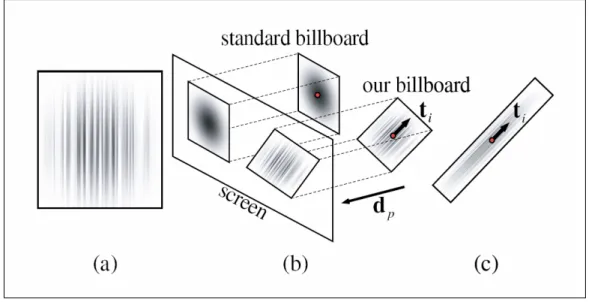
There are many hair rendering strategies applied in previous works. Bando et al’s hair representation with loosely connected particles [5] is an example of rendering groups of hair strands as a whole. In their rendering methodology, billboard elements that are lit by Kajiya-Kay model [9] are placed at the particle locations. To obtain the individual hair strand look, alpha mapping technique is applied to the billboard element (Figure 2.1).
Figure 2.1: Bando et al.’s rendering technique. a) The alpha map applied to the textures, b,c) The alpha map applied to the hair texture is translated to the hair particle location and scaled in the hair direction.
A more recent and visually appealing technique is Marschner et al.’s rendering model that takes the light scattering from individual hair fibers into account [10]. As seen in the Figure 2.2, in this work, a hair fiber is modeled as a transparent elliptical cylinder with an absorbing interior and a surface covered with tilted scales. This rendering technique results in very realistic hair visuals, but its computation intensive nature makes it impossible to perform this rendering technique in real-time. To obtain similar results with Marschner’s scattering model in real-time, precalculations can be performed and important Marschner terms can be stored as lookup textures (Figure 2.3) [11].
Figure 2.2: The hair fiber model used by Marschner.
2.4
Sketch-Based Interfaces
Creating 3D content in an intuitive way has become an active research area re-cently. Especially, sketch-based techniques have gained popularity to achieve this task. A number of researchers have proposed sketch-based direct manipulation interfaces to be used in computer graphics works. Thorne et al. [12] present a sketch-based animation system consisting of a character sketching tool and a mo-tion sketching tool. The character sketching tool infers the underlying kinematic skeleton of the sketched character. Motion sketching, on the other hand, requires information such as the type of motion, the spatial location of the motion, and the timing of the motion. To include such information, a gesture vocabulary is es-tablished. The input motion sketches are broken down to these vocabulary units and the final animation is synthesized. Another example usage of the sketch-based interfaces is in the Computer Vision area. Hengel et al.’s VideoTrace [2] is
Figure 2.3: The precalculated Marschner terms stored as textures.
a system for interactively generating 3D models of objects from video sequences. The model is extracted by first pre-processing the video sequence to describe the relationship between the camera and the scene and then tracing the shape of the target object over one or more frames of the input video sequence.
There are also sketch-based interfaces proposed for hair modeling and anima-tion. Wither et al. [13] present a sketching interface for physically-based hair styling. This approach consists of extracting geometric and elastic parameters of individual hair strands. The 3D, physically-based strands are inferred from 2D sketches by first cutting 2D strokes into half helical segments and then fit-ting these half helixes to segments. After sketching a certain number of guide strands, a volume stroke is drawn to set the hair volume and adapt the hair cut. Finally, other strands are interpolated from the guide strands and the volume stroke. Because of the mentioned fitting process, it is not possible to obtain a resultant physically-based strand that matches the user’s input stroke.Another physically-based hair creation technique is proposed by Hernandez et al. [14]. In this work, a painting interface is provided to create density and length maps. The created maps are then used to create individual hair strands represented by poly-lines. Because of this limited representation, the hairstyle parameters such as curliness and fuzziness cannot be used with this technique.
In contrast to these physically-based sketching tools, Malik [15] describes a tablet-based hair sketching user interface to create non-physically based hairstyles. In this approach, hair is represented as wisps, and parameters such as density, twist, and frizziness of a wisp are used to define the style of the hair. Additionally, with the help of gesture recognition algorithms and virtual tools, such as virtual comb or hair-pin, the style of drawn hair can be changed interac-tively. Another non-physically based hairstyle design system is proposed by Fu et al. [16]. Their design system is equipped with a sketching interface and a fast vector field solver. The user drawn strokes are used to depict the global shape of the hairstyle. The sketching system employs style primitive types: stream curve, dividing curve and ponytail. In this system, it is hard to provide local control over hairstyle without losing real-time property.
Hair Modeling
Instead of 2D polygonal [6], particle-based [5], and wisp-based [4] representations, we use a wisp structure consisting of a skeleton strand and number of imitator strands whose shape characteristics are determined by skeleton strand shape and wisp style parameters similar to Choe et al.’s work [3]. In this section, the strand structure, how they form wisps, and the patch structure used to place the formed wisps will be discussed.
3.1
Strands
Although it is possible to dynamically simulate each hair strand individually, to achieve our real-time objective, the overall hair model is implemented in a strand-wisp hierarchy. The basic blocks of the hair model are strands and they are di-vided into two categories: skeleton and imitator strands. Skeleton and imitator strands are formed by a number of control points. The skeleton strand’s con-trol points are recorded with our direct manipulation interface. These recorded control points are then used to generate Catmull-Rom splines (Figure 3.1) [17], which will be discussed in the “Hair Rendering” main section.
Figure 3.1: The control points are recorded as control points of the skeleton strand.
3.2
Wisps
The skeleton strand and imitator strands are combined to form the wisp structure. As stated before, in this work, the skeleton strand shape and recorded wisp style parameters are used to determine the shape of the imitator strands and thus the overall shape characteristic of the formed wisp. The used wisp style parameters are wisp closeness, wisp fuzziness, number of strands in a wisp, and strand thickness distribution (Figure 3.2) [3]. These parameters are discussed in detail in Style Recording section (Section 4.5).
Figure 3.2: The effects of wisp style parameters on overall wisp shape. a) constant wisp closeness, b) increasing wisp closeness, c) decreasing wisp closeness, and d) wisp under the effect of wisp fuzziness parameter.
3.3
Patch Structure
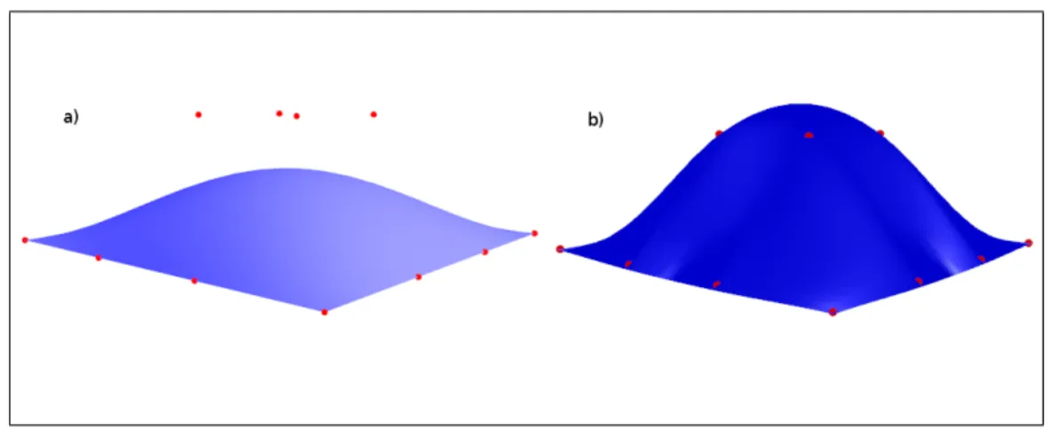
The hair structure needs to be placed on top of a surface to be used in an anima-tion context. Either a triangle mesh [18], or a spherical surface, or a parametric patch structure [4] has been used as a place holder for the hair in the previ-ous works. Because of its controllable and parameterizable nature, we use a Catmull-Rom patch structure to locate the formed wisps in our work. This patch representation choice allows us to decrease the dimension of the location problem from 3D to 2D space, and it also makes it easy to find the neighborhood informa-tion within a wisp, which is used to distribute the imitator strands around the skeleton strand. The reason for using a Catmull-Rom patch, rather than using the better known and simpler Bezier patch, is because of its better controllability. A Bezier patch does not pass through the defined central control points, whereas a Catmull-Rom patch passes through them. Figure 3.3 illustrates this difference. The downside of using a Catmull-Rom patch structure is that it has to be provided with (n + 2) × (n + 2) number of control points in order to ensure the
Figure 3.3: The difference between a) a Bezier patch and b) a Catmull-Rom patch with same control points.
patch to pass through the defined n × n control points. The needed additional control points are extrapolated using the original input control points (Figure 3.4). In our work, we observed that a Catmull-Rom patch with 6 × 6 control points is enough to represent the head model precisely. The used head model and the corresponding Catmull-Rom patch are shown in Figure 3.5.
Like every other parametric surfaces, the Catmull-Rom patch is also repre-sented in 2D parametric space by two parameters u and v that both vary from 0 to 1. In Figure 3.6, the changing u-v values are shown by assigning them to color values.
The usage of the Catmull-Rom patch in our work is discussed further in Chap-ter 4 Hair Sketching.
Figure 3.4: Extrapolation of additional control points from the original control points.
Hair Simulation
4.1
Dynamics Model
Implementing an efficient dynamics model is an important task to achieve real time hair simulation goal. In our case, preserving the stylistic properties of the hair is as important as achieving real time simulation speed. Therefore, in our work we use an inexpensive dynamics model, which is used for statistical hair models [3].
Our dynamics model separates the dynamical properties of the skeleton strand structure from the stylistic properties. We decompose the strand into two com-ponents, outline and detail comcom-ponents, in order to “separate intrinsic geometry of the strand from the deformations applied to it” [3].
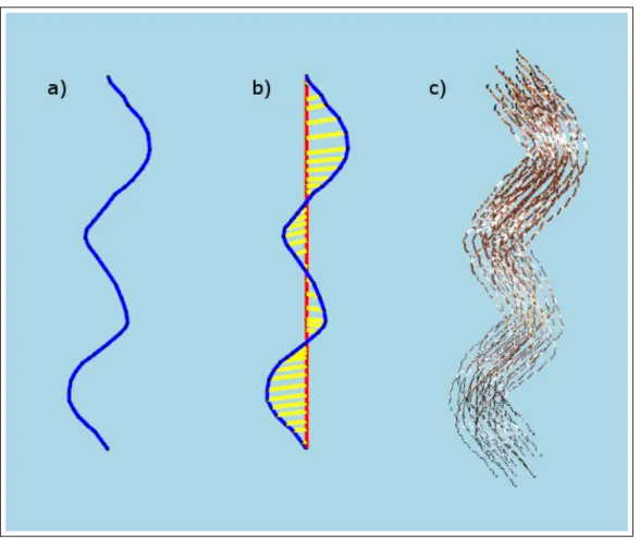
When a skeleton strand is drawn, it is processed by the dynamics model, to extract its physical and detail representative components (Figure 4.1). The component extraction process consists of a linear regression model as described below in which physical representative components are aligned with the axis of regression, and detail representative components become the vertical distance vector between the axis of regression and the skeleton strand points.
After the physical representative component is formed, physical mass points are produced on it and a distance preserving constraint [11] is applied on these mass points. The algorithmic flow of the process is as follows:
1. After the skeleton strand is drawn, the axis of regression vector starting from root ending at last control point is found,
2. Each control point of the skeleton strand − recorded at skeleton strand control point position recording phase of the hair sketching − is projected onto this axis, thus forming the physical masses of the strand,
3. Vectors starting from physical masses ending at corresponding control points make detail components, and vectors connecting neighbor physical masses make physical components,
4. Physical components are used to preserve the distance between their con-nected physical masses.
5. Once the above steps are complete, when simulating the created hair model using physically based techniques, input forces act on the created physical masses.
4.2
Dynamics Simulation
4.2.1
Numerical Integration Methods
In order to achieve real time simulation speeds, the time steps of the physical simulation should be as large as possible. Running a physical simulation is ac-tually solving a numerical ordinary differential equation (ODE), and large time steps in the simulation may bring incremental erroneous results with an incapable numerical integrator method.
Euler method is a first-order numerical procedure for solving ODEs. It is the most basic and simplistic method to solve an ODE. However, its simplistic nature
Figure 4.1: Physical model decomposition. a) The skeleton strand to be decom-posed, b) the detail (yellow rods) and physical (red rods) representatives extracted from the skeleton strand, c) the generated wisp.
brings errors with great magnitudes compared to other higher order integration methods.
The differential equation,
x0(t) = f (t, x(t)), x(t0) = x0 (4.1)
is approximated as follows by the Euler method:
where h is the step size forming the time sequence t0, t1 = t0 + h, t2 = t0 +
2h, t3 = t0+ 3h, ...
Verlet integration technique is another method for solving numerical ODEs. It is a second-order numerical procedure for solving ODEs, and this method yields better approximation of the differential equation. In this work, we implemented a modified Verlet integration technique to create a simple damping effect:
xn+1 = (2 − f )xn− (1 − f )xn−1+ anh2 (4.3)
Where f is the fraction of the velocity lost with the friction, and an is the
current acceleration value [24].
4.2.2
Physical Simulation Step
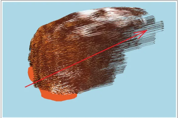
The two most effective forces related to hair simulation are gravity and wind forces. In our work, we employed these two forces. From these two, gravity is a constant force that does not change within the medium, however the direction and magnitude of the wind force can vary throughout the simulation. To achieve our real-time modeling and simulation tool objective, the varying wind forces are captured (Figure 4.2) while the dynamics simulation takes place.
At each physical simulation step, the gravity and wind forces are accumulated at physical mass points that are extracted by the dynamics model (Figure 4.1). The wind forces are captured with drawn strokes in the animation window. The wind direction is set to the unit vector starting with the stroke’s start point and ending at its end point and the magnitude of the wind force is set to the length of the drawn stroke (Figure 4.2). At the end of the physical simulation step, the accumulated forces at physical mass points are used to find the current acceleration value in the integration equation. Finally, the next position of the physical mass point is found by running the integration.
Figure 4.2: The drawn wind stroke and the produced wind force affecting the hair simulation.
4.3
Collision Detection
In hair simulations, two kinds of collision detection mechanisms should be consid-ered: hair-head collision detection and hair-hair collision detection. The hair-hair collision detection mechanism is not suitable for real-time operations because of excessive number of calculations needed. According to Choe et al.’s work [19], these calculations take over 50% of the simulation time, thus preventing the sim-ulation from being real-time. In light of these facts, in our work we implemented only the hair-head collision detection mechanism as described below.
4.3.1
Collision Detection Structures
Spherical volumes are ideal for collision detection purposes, because of the low cost intersection detection calculations. There are other solutions such as implicit
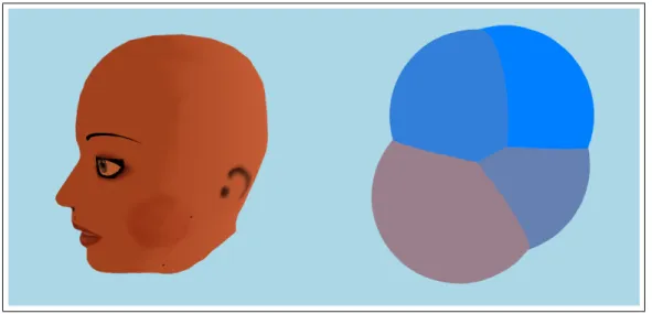
surfaces, but they require extra clock cycles that should be saved for our real-time objectives. Therefore, spherical volumes are used to determine collision between hair wisps and head model. The used head model required at least four spherical volumes to cover up the entire model. Thus, the head model is represented as a combination of four spherical volumes (Figure 4.3). These spherical volumes for the head model are placed and scaled manually.
Figure 4.3: The used head model and the corresponding combination of collision spheres for hair-head collision detection.
Spherical volumes are used for representing hair wisps for collision detection purposes. For each control point of the skeleton strand of a wisp, one spherical volume is positioned at the corresponding control point. The radii of the spheres are set according to the stored closeness values of the skeleton strand control points. This way, it is ensured that the wisps will not pass through the head structure. (Figure 4.4).
4.3.2
Collision Detection-Response Step
A collision detection step is performed at each simulation step. In collision detec-tion step, wisp spherical volumes are checked against head spheres and a response is generated to prevent the penetration if a collision is detected. To generate the
Figure 4.4: a) A skeleton strand that has increasing wisp closeness style param-eter, b) the resultant wisp, c) wisp collision spheres located at skeleton strand control points scaled according to wisp closeness style parameter, d) final wisp with located collision spheres.
response, collision related information such as contact normal (CN ) and penetra-tion amount (P A) are needed. By using spherical volumes as collision detecpenetra-tion structures, these information can be extracted easily (Figure 4.5).
When a collision is detected, the response generation process works as follows:
• The control point that is collided with the head spherical volume is trans-lated by P A in the direction of CN ,
• The corresponding physical mass is updated by using the detail vector that was extracted by the dynamics model.
Hair Sketching
5.1
Mapping From 2D to 3D
In this work, input to create 3D hair content is taken from a stylus, which is a 2D input device. Thus, 2D input strokes have to be mapped to 3D. This mapping process is accomplished by algorithms taking advantage of graphical hardware and OpenGL graphics library. In the following sections, these algorithms areR
discussed.
5.2
Skeleton Strand Root Positioning
A skeleton strand is the master strand in a wisp, which is responsible for the style and movement of imitator strands located on that wisp. The first step of the hair sketching tool is then locating the root point of the skeleton strand. To achieve this goal, as stated before, we fit a Catmull-Rom patch on the surface of the head model.
When the tool is in idle state (i.e. a wisp is not being sketched), the user’s first input point is considered as a root candidate. This candidate point has to
be tested against the patch structure, to find out whether it is on the patch or not. This test is performed as follows (Program 1):
• The depth buffer of the graphics processor is cleared,
• The patch is rendered with flat shading (the shading of the patch is not important, rendering fills the depth buffer),
• The depth buffer is read at the candidate point location (xc , yc),
• According to the graphics pipeline matrices; xc , yc, and depth component
are unprojected with OpenGL’s gluUnProject function [25] to obtain world coordinates x, y, and z,
• If the point with x, y, and z coordinates is inside the bounding-box of the patch, this point is on the patch.
If the point is on the patch, the point is registered as a skeleton strand root. The 3D coordinates (x, y, and z) of the root point are converted to the u-v coordinate system of the patch, in order to be used at a later stage, during the wisp formation phase. This conversion is performed by checking the intersection of the point with the triangles forming the patch. The u-v coordinates of the triangle vertices are known, thus the u-v coordinates of a point inside a triangle are interpolated from these u-v coordinates.
5.3
Skeleton Strand Control Point Position
Recording
After the root of the skeleton strand is determined, other control points of the strand are recorded. These control points are recorded as follows:
• A rectangular plane that is perpendicular to the camera look at vector and passes through the last recorded control point is rendered to the screen, • The depth buffer is read at the input point location (x, y),
• According to the graphics pipeline matrices, x, y and depth component are unprojected to obtain world coordinates x,y, and z,
• If the obtained world coordinates appear to be inside the head (invalid position), the depth buffer is cleared, the patch is rendered and input points (x and y) are tested against the patch.
5.4
Gesture Recognition
Using planar elements while recording the skeleton strand control points may lead to unrealistic hair structure results when skeleton strand is sketched as a combination of loops to represent curly hair style as can be seen in Figure 5.1. Therefore, we employ a gesture recognition step that detects if there are any loops on the drawn hair wisps, by inspecting the intersections of the segments that form the skeleton strand.
When a number of segments of a skeleton strand form a convex polygon, this means that the skeleton strand contains a loop. If not corrected, these loops would introduce artifacts such as a hair wisp passing through itself. In order to prevent this unwanted effect, in our work these loops are mapped to a 3D helical structure. To perform this mapping, the focal point of the detected loop is found and a 3D axis of rotation is placed at this focal point (Figure 5.2). The control points forming the loops are mapped to a helical structure by using this axis of rotation (Algorithm 1).
Figure 5.1: The skeleton strand that is sketched as a combination of loops.
5.5
Style Recording
The style of an individual wisp is represented by a number of style parameters, such as closeness ci,j, fuzziness fi,j, number of strands in a wisp ni and strand
thickness distribution ti,j (where i is the number of wisp and j is the number
of recorded control point in that wisp). These parameters, except the number of strands and the thickness distribution, are recorded for each control point of the skeleton strand, so that it is possible to vary them within a single wisp. Figure 5.3 illustrates the effect of style parameters on the wisp shape.
In our work, a tablet stylus pen is used to capture the closeness and fuzziness style parameters. Besides giving the positional information, our stylus pen input device is capable of providing other input information, such as pen pressure and pen tilt amount. To implement a direct manipulation user interface, we have made use of these input parameters and mapped them to the mentioned style parameters. The closeness style parameter is captured with pen pressure amount, and the fuzziness style parameter is captured with pen tilt amount.
Algorithm 1 Mapping of control points to a helical structure CPs← processed loop’s start point
CPe← processed loop’s end point
IB1...IBn ← control points between CPs and CPe
α ← 0
∆α ← 360/n
r ← radius of the loop ~
D ← (CPe− CPs)/n
for i = 1 to n do ~
T ← ˆir {ˆi is the x-unit vector}
IBi ← ~T rotated around ~D by α degrees
IBi ← IBi+ ~Di
α ← α + ∆α end for
5.6
Wisp Formation
After the recording of the segments is completed, an individual wisp is formed according to the recorded control points and wisp style parameters. The captured control points and parameters are fed into a GPU vertex shader to create Catmull-Rom Splines of the skeleton and imitator strands. Imitator strands’ root points are distributed around the skeleton strand root uniformly, using the employed patch structure and Archimedes’ spiral (Figure 5.4). The reason for using the Archimedes’ spiral is that with its polar equation, it can provide low computation cost for circular uniform distribution of points.
Archimedes spiral is a spiral with polar equation:
r(θ) = αθ (5.1)
Where αcontrols the distance between successive turnings that matches our closeness style parameter. If we adapt this to our model, the equation becomes:
Figure 5.2: The process to solve a) ill defined skeleton strand sketches; b) the loops, loop directions and loop focal points are detected, c) by placing axis of rotation to focal points, the control points forming the loops are mapped to helical structures.
Because a patch structure is employed for locating strands in a wisp, we can map patch coordinates to polar coordinates as follows:
u = r cos(θ) (5.3) v = r sin(θ)
Replacing r with Equation 5.2, we get the patch parameters as follows:
u = ci,jθ cos(θ) (5.4)
v = ci,jθ sin(θ)
The distances between the skeleton strand root point and the distributed imitator strand roots define the offset distances of the remaining control points
Figure 5.3: The effects of the styling parameters: a) Constant closeness parame-ter, b) increasing closeness parameparame-ter, c) decreasing closeness parameparame-ter, d) the fuzziness parameter in effect.
of the imitator strands from the control points of the skeleton strand. In a wisp, in other words, if closeness is kept constant and no fuzziness is applied to the remaining control points, imitator strands keep these offset distances. The role of the fuzziness style parameter is to produce uneven looking wisps. The increased value of fuzziness parameter results in a more perturbed imitator strand control point location (Figure 5.5).
Figure 5.4: The Archimedes’ spiral on the Catmull-Rom patch u-v space. The points are obtained with 30 degree increments. The left hand spiral’s closeness parameter ci,j is greater than the right hand spiral’s closeness parameter.
Figure 5.5: The blue vector represents the offset distance for that control point. According to the fuzziness parameter, the corresponding control point of the imitator strand is perturbed by randomly replacing it in the volumes defined by perturbation spheres. As fuzziness increases, the control point is randomized in a bigger perturbation sphere.
Hair Rendering
Visually realistic hair rendering is a must for acceptable hair simulations. It is possible to render hair according to its physical properties. However, physically correct hair rendering would bring significant computational loads. To accomplish our real-time speed objective, we have employed approximations of physically correct rendering equations and made use of programmable GPUs.
“A graphics processing unit or GPU is a dedicated graphics rendering device for a personal computer, workstation, or game console. Modern GPUs are very efficient at manipulating and displaying computer graphics, and their highly par-allel structure makes them more effective than general-purpose CPUs for a range of complex algorithms” [20]. In the year of 2000, GPUs gained programmability property and since then, they are being used for graphical computations. Al-gorithms that can consume valuable CPU time are mapped to GPUs via the language Cg [21] to take advantage of their highly parallel structure. In the fol-lowing sections, the hair rendering algorithms and their implementation details are discussed.
6.1
Catmull-Rom Spline Generation with GPU
Catmull-Rom spline is a cubic spline that enforces the spline to pass through the input control points. From the given control points C0..3, a Catmull-Rom spline starting from C1 and ending at C2 is obtained (Figure 6.1).
Figure 6.1: With the given control points C0,C1,C2,C3, a spline from C1 to C2 is
obtained.
Therefore, in our work, when a user sketches a skeleton strand with n control points, the extra two control points needed for Catmull-Rom spline are extrapo-lated using the control points C0,C1 and Cn−1,Cn−2 as seen in the Figure 6.2.
After the extrapolation operation, the n + 2 control points are grouped into sets of 4 control points (Figure 6.3). From these sets of control points, Bezier spline pieces are obtained. By combining these Bezier spline pieces, the Catmull-Rom splines are obtained. Thus the 4 control points (C0,C1,C2,C3) are used to
generate Bezier spline control points as follows:
Figure 6.2: The extrapolation process of the additional Catmull-Rom spline con-trol points.
BC1 = C1+ ((C2 − C0)/6)
BC2 = C2− ((C3− C1)/6)
BC3 = C2
These 4 Bezier control points are then fed into the Bezier equation to obtain the part of the Catmull-Rom spline.
For 0 ≤ t < 1,
B(t) = BC0(1 − t)3+ 3BC1t(1 − t)2+ 3BC2t2(1 − t) + BC3t3 (6.2)
“The rendering pipeline is mapped onto current graphics acceleration hard-ware such that the input to the graphics card (GPU) is in the form of vertices. These vertices then undergo transformation and per-vertex lighting. At this point
in modern GPU pipelines a custom vertex shader program can be used to ma-nipulate the 3D vertices prior to rasterization” [22]. In our work, the vertex shader program (Program 2) is used to generate Catmull-Rom splines from the input control points and some dummy vertices that are “manipulated” to form the vertices of the spline (Figure 6.4 and Program 2).
6.2
Kajiya-Kay Lighting Model
The Kajiya-Kay lighting model is an anisotropic strand lighting model [9]. In our work, the implementation of the Kajiya-Kay model is based on the well known Phong shading.
Ip = kaia+ (kd(L · N )id+ ks(R · V )αis) (6.3)
In Kajiya-Kay lighting model, hair strand tangent (T) is used instead of nor-mal (N) in lighting equations.
Ip = kdsin(T, L) + ks∗ ((T · L)(T · V ) + sin(T, L)sin(T, V ))α (6.4)
In the graphics pipeline, after the vertex shader program manipulates the input vertices, “the vertices undergo clipping and rasterization resulting in frag-ments. A second custom shader program (fragment shader program) can then be run on each fragment before the final pixel values are output to the frame buffer for display” [22]. In our implementation of the Kajiya-Kay lighting model; for each fragment, the tangent of the hair segment is fed to the fragment shader from the vertex shader program. With the tangent, light and view vectors known, the final color of the fragment is computed in the fragment shader program (Program 3).
Results
7.1
Performance Results
The computationally intensive physically based animation sequences were pro-duced with a standard laptop PC (Intel Core 2 Duo T7500 2.2 GHz CPU, 2 GB RAM) with a video card NVIDIA GeForceR 8600M GT. Although GPU pro-R
gramming techniques are not used for the physical calculations, we were able to obtain the following results while the full hair-head collision detection procedures are in operation.
Table 7.1: The performance of the tool under different wisp and strand numbers.
# of wisps # of strands fps
50 1250 36
50 5000 24
100 2000 25
These results show that it is possible to interact with the tool in real-time while under heavy physical calculations.
7.2
Visual Results
Figure 7.2: The created hair model is under the effect of wind force.
Figure 7.4: A punk hair model.
Figure 7.5: Another punk hair model created by a first time user in 3 minutes 30 seconds.
Conclusion
This thesis introduced stylistic hair modeling and physically based animation creation tool with a sketch-based direct manipulation interface. Apart from pro-viding a sketch-based interface, the tool operates at real-time speeds in both hair modeling and animation phases. The creation of such a tool needs inspection of the problem from different aspects such as hair modeling, physically based hair simulation, hair sketching, and hair rendering.
We have adopted a previous approach in modeling the hair that uses wisps as basic hair structures. The stylistic properties of hair are represented with wisp style parameters such as fuzziness and closeness. These stylistic properties of hair have to be preserved during a dynamics simulation, so the used hair model is enhanced by a dynamics model employing a process that decomposes the physical and stylistic components of hair. The physical forces are therefore applied only on the physical components of hair. Alternative to this approach, a more natural representation of hairstyles such as cosserat-rod model [8] can be implemented on GPU to work in real-time speeds. For solving ordinary differential equations, the euler numerical integration and verlet numerical integration methodologies are examined. From these two, a modified verlet integration is used in solving dynamics equations. Currently, hair under effect of hairstyling products such as hair gel is not supported, as an extension the effect of such products and water can be implemented.
The sketching interface of the tool has to deal with the problem of mapping 2D input coordinates to 3D world coordinates. We have dealt with this problem by using OpenGL’s API functions and the graphics card’s internal buffer structures. In order to achieve our real-time hair modeling and real-time hair simulation objectives, we made use of programmable GPUs in hair rendering context. The operations such as Catmull-Rom spline generation and anisotropic Kajiya-Kay illumination, which would consume many CPU cycles, were implemented on pro-grammable GPUs.
To find out the strongest and weakest points of the tool, a simple usability test is applied by using the hallway testing methodology. Testers were allowed to choose one task from three choices and observed while using the tool to complete the chosen task. Apart from the usability test, performance and visual results were also provided.
By employing the discussed methods, we were able to create a real-time op-erating tool for modeling hair and creating dynamics simulations. With our tool, it is possible to prototype hair models and simulations rapidly.
[1] Shneiderman, B. 1987. Direct manipulation: A step beyond programming languages. In Human-Computer interaction: A Multidisciplinary Approach, R. M. Baecker, Ed. Morgan Kaufmann Publishers, San Francisco, CA, 461-467.
[2] van den Hengel, A., Dick, A., Thormhlen, T., Ward, B., and Torr, P. H. 2007. VideoTrace: rapid interactive scene modelling from video. In ACM SIGGRAPH 2007 Papers (San Diego, California, August 05 - 09, 2007). SIGGRAPH ’07. ACM, New York, NY, 86.
[3] Choe, B. and Ko, H. 2005. A Statistical Wisp Model and Pseudophysical Approaches for Interactive Hairstyle Generation. IEEE Transactions on Vi-sualization and Computer Graphics 11, 2 (Mar. 2005), 160-170.
[4] Kim, T. and Neumann, U. 2002. Interactive multiresolution hair modeling and editing. ACM Trans. Graph. 21, 3 (Jul. 2002), 620-629.
[5] Y. Bando, B-Y. Chen, and T. Nishita. Animating hair with loosely connected particles. Computer Graphics Forum, 22(3):411–418, 2003. Proceedings of Eurographics’03.
[6] C. Koh and Z. Huang. A simple physics model to animate human hair mod-eled in 2D strips in real time. In EG workshop on Computer Animation and Simulation (EG CAS’01), pages 127–138, September 2001.
[7] M. Oshita. Real-time hair simulation on GPU with a dynamic wisp model. Computer Animation and Virtual Worlds, Vol. 18, No. 4-5. (2007), pp. 583-593.
[8] F. Bertails, B. Audoly, B. Querleux, F. Leroy, J.-L. Lvque, and M.-P. Cani. Predicting natural hair shapes by solving the statics of flexible rods. In J. Dingliana and F. Ganovelli, editors, Eurographics’05 (short papers). Euro-graphics, August 2005. Eurographics’05 (short papers).
[9] Kajiya, J. T. and Kay, T. L. 1989. Rendering fur with three dimensional textures. SIGGRAPH Comput. Graph. 23, 3 (Jul. 1989), 271-280.
[10] Marschner, S. R., Jensen, H. W., Cammarano, M., Worley, S., and Hanrahan, P. 2003. Light scattering from human hair fibers. In ACM SIGGRAPH 2003 Papers (San Diego, California, July 27 - 31, 2003). SIGGRAPH ’03. ACM, New York, NY, 780-791.
[11] Nguyen, H., and Donelly, W. 2005. Hair animation and rendering in the nalu demo. GPU Gems 2, 361–380.
[12] Thorne, M., Burke, D., and van de Panne, M. 2004. Motion doodles: an interface for sketching character motion. ACM Trans. Graph. 23, 3, 424– 431.
[13] Wither, J., Bertails, F., and Cani, M. 2007. Realistic Hair from a Sketch. In Proceedings of the IEEE international Conference on Shape Modeling and Applications 2007 (June 13 - 15, 2007). SMI. IEEE Computer Society, Washington, DC, 33-42.
[14] Hernandez, B. and Rudomin, I. 2004. Hair Paint. In Proceedings of the Computer Graphics international (June 16 - 19, 2004). CGI. IEEE Computer Society, Washington, DC, 578-581.
[15] Shahzad Malik. ”A Sketching Interface for Modeling and Editing Hairstyles”. In Proceedings of Eurographics Workshop on Sketch Based Interfaces and Modeling (EGSBM) 2005, Dublin, Ireland. p. 185-194.
[16] Hongbo Fu, Yichen Wei, Chiew-Lan Tai, Long Quan. Sketching hairstyles. EUROGRAPHICS Workshop on Sketch-Based Interfaces and Modeling (SBIM 2007). August 2-3, University of California, Riverside, U.S.A.
[17] Catmull, Edwin and Rom, Raphael, A class of local interpolating splines, in R.E. Barnhill and R.F. Riesenfed (eds.) Computer Aided Geometric Design, Academic Press, New York, 1974, 317-326.
[18] Rui Zhang and Burkhard C. Wuensche, Interactive Styling of Virtual Hair. Proceedings of IVCNZ ’06, Great Barrier Island, New Zealand, 27-29 Novem-ber 2006, pp. 143-148
[19] Choe, B., Choi, M. G., and Ko, H. 2005. Simulating complex hair with robust collision handling. In Proceedings of the 2005 ACM Siggraph/Eurographics Symposium on Computer Animation (Los Angeles, California, July 29 - 31, 2005). SCA ’05. ACM, New York, NY, 153-160.
[20] ”What is a GPU?” nVIDIA. 26 May 2008 <http://www.nvidia.com/content/nsist/module/what gpu.asp>.
[21] ”Welcome to the Cg Homepage.” Cg. nVIDIA. 28 Apr 2008 <http://developer.nvidia.com/page/cg main.html>.
[22] ”Graphics pipeline.” Wikipedia. 28 Apr 2008 <http://en.wikipedia.org/wiki/Graphics pipeline>.
[23] Barnicle, K. 2000. Usability testing with screen reading technology in a Win-dows environment. In Proceedings on the 2000 Conference on Universal Us-ability (Arlington, Virginia, United States, November 16 - 17, 2000). CUU ’00. ACM, New York, NY, 102-109.
[24] ”Verlet integration.” Wikipedia. 14 May 2008 <http://en.wikipedia.org/wiki/Verlet integration>.
[25] OpenGL Architecture Review Board, C. 1997 OpenGL Reference Manual (2nd Ed.): the Official Reference Document to Opengl, Version 1.1. Addison-Wesley Longman Publishing Co., Inc.
[26] A. Daldegan, N. Magnenat-Thalmann, T. Kurihara, and D. Thalmann. An integrated system for modeling, animating and rendering hair. Computer Graphics Forum, 12(3):211–221, 1993.
Hair Modeling and Physical
Simulation Workflow
Our tool consists of two main screens. Hair modeling screen, in which hair models are created and saved, and physical simulation screen, in which the saved hair models are simulated under gravity and wind forces.
A.1
Hair Modeling Screen
Hair modeling screen can be activated by pressing “1”. In the hair modeling screen, the skeleton strands of hair wisps can be sketched onto a head model that is initially empty (Figure A.1). The head model can be rotated around its y-axis by pressing “8”. The control points of the skeleton strands are recorded at fixed time intervals (50 ms). Therefore, a skeleton strand that is sketched slowly will have closer control points, whereas a quickly sketched skeleton strand will have more separated control points (Figure A.2).
The wisp style parameters (closeness and fuzziness) are also recorded in hair modeling screen per control point of a skeleton strand. Stylus-pen tilt/pressure
Figure A.1: The empty head model.
amount or keyboard input (F12/F11 for +/− closeness, F10/F9 for +/− fuzzi-ness) are used to record wisp style parameters. When the sketching of the skeleton strand is completed, the wisp that is under the effect of recorded wisp style pa-rameters is created and shown on the screen. This way, the user can see the resultant wisp on the fly (Figure A.3). Pressing “x” will undo the last sketched wisp.
After hair modeling is completed, the created hair model can be saved by pressing “p”.
A.2
Physical Simulation Screen
Physical simulation screen can be activated by pressing “2”. If there is a saved hair model from the hair modeling screen, pressing “l” will load the saved hair model to the physical simulation screen. In this screen, the wind force affect-ing the simulation can be controlled by sketchaffect-ing the wind force direction and magnitude (Figure A.4).
Figure A.2: From left-to-right, quickly sketched skeleton strand, normally sketched skeleton strand, and slowly sketched skeleton strand.
Figure A.4: The drawn wind stroke and the produced wind force affecting the hair simulation.
Usability Test
For extracting the usability results, Hallway Testing is used. Hallway Testing is a specific methodology of software usability testing, whose principle is using a group of five to six random people rather than using a trained group of testers [23]. For testing, a list of tasks (Table B.1) with varying difficulty levels are prepared.
Table B.1: The task list determined for the testing.
Task Number Task Description
1 Create a punk hairstyle
2 Create a wavy hair and make it float with the wind to the right
3 Create a curly hairstyle
Also a pretest questionnaire is prepared to gather information about the testers such as age, gender and familiarity with the computer systems (Table B.2). While taking the tests, the testers are let to think aloud to instantly re-ceive the feedback from them.
Table B.2: The general test profile extracted from one day long test sequence.
Tester 1 2 3 4
Gender F F M M
Age 19 31 35 22
Profession Student Civil
Engi-neer Civil Engi-neer Computer Engineer Familiarity with computers (1-5) 3 2 3 5 Familiarity with graphics soft-ware (1-5) 2 2 1 4
Selected Task Curly hair Punk hair Punk hair Wavy hair
Time to
com-plete the
task(mins)
4.21 5 3.30 4.40
From the Think Aloud Protocol [23], the following evidences about the tool are summarized.
Natural / Intuitive Interface. With the sketch-based direct manipulation in-terface, the testers were able to create hair models and dynamics simulations in a short time. It was not needed to explain the hair model creation interface. The testers have found the model-animation creation phases natural and intuitive.
Rapid Hair Model Creation. Our sketching tool makes it possible to create hair models with different stylistic properties in a short amount of time. By using direct manipulation techniques to create different hair styles, users do not need to use other interfaces and this property decreases the hair model creation time. Rapid Hair Animation Prototyping. With our tool, it is possible to create physically based hair simulations. These simulations can be prototyped rapidly and can be controlled with the sketch-based interface. The drawn strokes at simulation phase are used to determine the direction and magnitude of the wind force affecting the hair model.
artistic techniques like hatching and shading. One tester commented on this limitation when s/he tried to sketch the hair model with hachures and received an unexpected output wisp structure. Another received comment in the hair modeling phase of the tool was about the drawing boundaries of the hair. When the tester tried to place the skeleton strand root to a coordinate that is not contained within the patch surface, the tool -as expected- did not create a wisp. In response to this, the tester commented that a hair drawing boundary shown on the head model may be useful to overcome this. Another useful comment was about the presence of hard-to-reach areas on the head structure. Although it is possible to rotate the head model in 3-axis by using the keyboard, it is not the best interface. Thus, a mouse or a stylus-pen interface have to be provided to the user for rotating the head model.