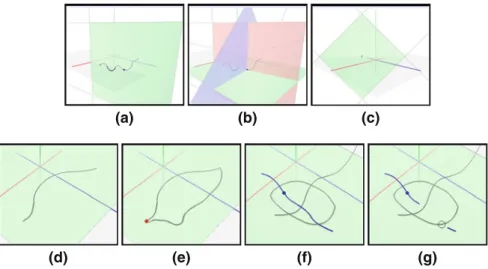
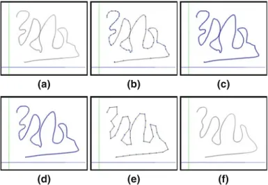
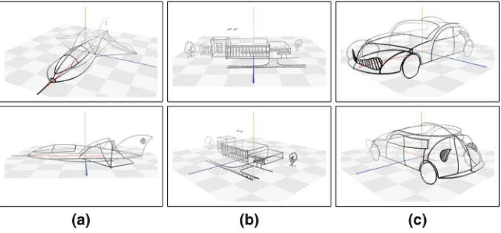
Paper and pen: A 3D sketching system
Tam metin
Şekil

Benzer Belgeler
This thesis employed user experience (UX) methods from consumer industries with pragmatic mixed-methods in order to explore this issue. The research questions addressed a number of
Sir Syed thought education as p a n a c e a for all the evils prevailing in the contemporary Muslim community and persuaded the Muslims to avail the facilities provided by the
There are different index for oils; free fatty acids index, refraction index, saponification index, iodine index.. Foreign oils, mineral oils and dyes are searched
When we reached 2006, the positive differential in support of EU membership, favoring the Cluster 3 provinces, has turned into a negative differential since these
If upper arm bridge grafts are used before the basilic vein, performing the basilic vein transposition technique can be impossible or very difficult because of the
Padişahla, vükelâsının ekser gün leri talimgahlarda geçiyor, kâh Kâ- ğıdhanede top talimleri görülüyor, kâh Levendde nizamı cedid kıta ları gözden
If an intersection between the two bounding volumes is found (bounding volume of human model and bounding volume in the leaf node of cloth model’s hierarchy), then geometrical
öğrenmiştim ama şairliğini, insanlığını ve vatanseverliğini daima ön planda tuttuğum için - ayrıntı saydığım- bu yanını kitaplarıma (Kişiler. ve
