DESIGN, CONTROL, FABRICATION AND
MANEUVERABILITY ANALYSIS OF AN
UNTETHERED MINIATURE SOFT ROBOT
a thesis submitted to
the graduate school of engineering and science
of bilkent university
in partial fulfillment of the requirements for
the degree of
master of science
in
mechanical engineering
By
Cem Ayg¨
ul
September 2019
DESIGN, CONTROL, FABRICATION AND MANEUVERABILITY ANALYSIS OF AN UNTETHERED MINIATURE SOFT ROBOT By Cem Ayg¨ul
September 2019
We certify that we have read this thesis and that in our opinion it is fully adequate, in scope and in quality, as a thesis for the degree of Master of Science.
Onur ¨Ozcan(Advisor)
Bilge Baytekin
¨
Ozg¨ur ¨Unver
Approved for the Graduate School of Engineering and Science:
ABSTRACT
DESIGN, CONTROL, FABRICATION AND
MANEUVERABILITY ANALYSIS OF AN
UNTETHERED MINIATURE SOFT ROBOT
Cem Ayg¨ul
M.S. in Mechanical Engineering Advisor: Onur ¨Ozcan
September 2019
As the robotics field grows, it searches for new potential workspaces to be in-teracting with. The conventional robotics, which involves utilization of robots made out of hard materials like metals and hard plastics, has helped humankind automatebmany different sorts of labor and such robots have been assisting the humans in various tasks. Nevertheless, some environments require very delicate interactions and adaptability of the robots to unstable elements and obstacles. A fairly new sub-field of robotics, soft robotics, arises as a very alluring area of research as it promises advancements in these particular premises beyond the conventional hard robotics.
A major point of dispute arises around the term ’softness’ as some specific robots achieve softness via the use of soft materials (specific polymers like PDMS) whereas although some others are made out of hard materials, they behave in a soft manner thanks to clever use of the mechanisms involved in them. The robot in this work is fully made out of soft structural materials and uses a flexible circuit board. The electronics, actuators and several little connection parts are hard.
The robot that is designed and constructed is a soft-hybrid robot that can be considered as a preliminary standpoint for autonomous robots to be operating in challenging working environments such as earthquake zones, pipelines, rough terrain military areas and so on. Miniature sized, it can be fitted with various sensors and communication devices in order to be used for search and rescue, surveillance and patrol missions. Its soft legs, body, and circuit enables it to overcome obstacles that conventional hard miniature robots tend to be tackled
iv
The work I did involves mostly iterative sequences due to the challenges of modeling the soft components’ behavior. Different leg mechanisms with different types of actuators are evaluated. Some of the evaluated mechanisms utilize a kinematic chain whereas the final version does not. These can be considered the novel aspects of the work done as virtually no examples in the literature use kinematic chains in soft robots.
Thus, my work can be considered to be a multi-disciplinary study that involves design and fabrication of different soft locomotion mechanisms, body designs, and flexible circuit boards. Finite element analyses are conducted in order to estimate differences between different leg mechanisms and soft joints. Finally, by the help of specific sensors and microcontrolling elements, the whole robot is controlled to maneuver in the desired behavior.
Keywords: Robotics, Soft Robotics, Miniature Robotics, Safe Interaction, Com-pliant Mechanisms, Four-Legged Robots, Locomotion Mechanism Design.
¨
OZET
KABLOSUZ M˙INYAT ¨
UR B˙IR YUMUS
¸AK ROBOTUN
D˙IZAYNI, KONTROL ¨
U, ¨
URET˙IM˙I VE MANEVRA
KAB˙IL˙IYET˙I ANAL˙IZ˙I
Cem Ayg¨ul
Makine M¨uhendisli˘gi, Y¨uksek Lisans Tez Danı¸smanı: Onur ¨Ozcan
Eyl¨ul 2019
Robotik ara¸stırma alanı b¨uy¨ud¨uk¸ce, yeni potansiyel i¸s alanları ile etk-ile¸sime girebilme ¸cabası g¨or¨ulmektedir. Metaller ve sert plastikler gibi sert malzemelerin kullanıldı˘gı geleneksel robotik alanı, insanlı˘ga bir¸cok farklı i¸s alanının otononla¸stırılması konusunda yardım etmekte ve aynı zamanda yine bir¸cok farklı g¨orevde de insanlara yardım etmektedir. Fakat, bazı ¸cevreler ¸cok hassas etkile¸simler gerektirmekte ve robotların ¸cevredeki istikrarsız ¨o˘gelere ve engellere kar¸sı uyumlu olabilmelerini gerektirmektedir. Roboti˘gin nispeten yeni bir alanı olan yumu¸sak robotik bu alanlarda geleneksel sert roboti˘ge kar¸sı daha ¸cok ¸sey vaadetti˘gi i¸cin ¸cok ilgi ¸cekici bir ara¸stırma alanı olarak ¨one ¸cıkmaktadır.
Bu alandaki b¨uy¨uk tartı¸sma noktalarından biri de ’yumu¸saklık’ terimi ¨uzerine ya¸sanmaktadır. Bazı robotlar yumu¸saklı˘gı ¨uretildi˘gi malzemelerin yumu¸sak ol-ması ile sa˘glarken (PDMS gibi spesifik polimerler ¨ornek olarak verilebilir) bazı robotlar ise sert malzemelerden ¨uretilmi¸s olmalarına kar¸sın bu malzemelerin uyumlu davranı¸sları sebebiyle yumu¸sak olarak nitelendirilmektedirler. Bu ¸calı¸smadaki robot ise tamamen yumu¸sak yapısal malzemelerden ¨uretilmi¸s olup aynı zamanda esnek bir devre kartı kullanmaktadır. Elektronikler, eyleyiciler ve bazı k¨u¸c¨uk ba˘glantı par¸caları ise serttir.
vi
Tasarlanan ve ¨uretilen robot bir yumu¸sak-hibrit robot olmakla beraber de-prem alanları, boru hatları, zorlu askeri araziler gibi alanlarda otonom olarak op-erasyon ger¸cekle¸stirebilecek robotlar i¸cin bir ba¸slangı¸c noktası olarak g¨or¨ulebilir. Minyat¨ur boyutları sayesinde ¨uzerine yerle¸stirilecek farklı sens¨orler ve ileti¸sim cihazları sayesinde arama kurtarma, g¨ozetleme ve devriye gibi g¨orevlerde kul-lanılabilir. Yumu¸sak bacakları, g¨ovdesi ve devre kartı geleneksel sert robotların takılması muhtemel olan engelleri ge¸cmesini sa˘glar.
Yumu¸sak komponentlerin modellenmesinin b¨uy¨uk zorluklar i¸cermesi sebebiyle ¸calı¸smam ¸co˘gunlukla tekerr¨ur eden sekanslar i¸cermektedir. Farklı eyleyiciler ile s¨ur¨ulen farklı y¨ur¨uy¨u¸s mekanizmaları de˘gerlendirilmi¸stir. Bazı de˘gerlendirilen mekanizmalar kinematik zincirler i¸cerirken final versiyonu i¸cermemektedir. Bun-lar bu ¸calı¸smanın ¨ozg¨un noktaları olarak de˘gerlendirilebilir ¸c¨unk¨u ¸su ana kadar literat¨urde olan yumu¸sak robotların neredeyse hi¸c biri kinematik zincir-ler i¸cermemektedir.
B¨oylelikle, ¸calı¸smak bir¸cok farklı disiplinin bir arada bulundu˘gu ve farklı yumu¸sak y¨ur¨uy¨u¸s mekanizmalarının, g¨ovde tasarımlarının ve esnek devre kart-larının dizayn ve ¨uretimini i¸ceren bir ¸calı¸sma olarak ¨one ¸cıkmaktadır. Sonlu eleman analizleri kullanılarak farklı bacak mekanizmaları ve yumu¸sak eklemler kar¸sıla¸stırılmı¸stır. Son olarak, spesifik sens¨or ve devre elemanlarının yardımı ile robotun istenilen ¸sekilde hareket edece˘gi kontrol sistemi olu¸sturulmu¸stur.
Anahtar s¨ozc¨ukler : Robotik, Yumu¸sak Robotik, Minyat¨ur Robotik, G¨uvenli Etkile¸sim, Uyumlu Mekanizma, D¨ort Bacaklı Robotlar, Hareket Mekanizması Tasarımı.
Acknowledgement
I would like to take this opportunity in order to thank several different people that have contributed to this work in various manners and supported me in hard times. First and foremost, I want to thank my advisor, Asst. Prof. Onur ¨Ozcan who stimulated interest in me such that I decided to work on soft robotics at the very beginning. His guidance through bottlenecks, visionary suggestions and most importantly; sincere and big brotherly support helped me walk through this hard process of creating the robot.
In addition, I would like to thank my fianc´e ¨Ozge Ko¸c, who has always been there for me ever since I’ve known her; and her love and support pushed me forward in my hardest times tackling the problems research was presenting. Her existence is what makes me drive forward in life.
I want to thank Joanna Kwiczak-Yi˘gitba¸sı and Bilge Baytekin, who always helped me with the fabrication and other chemical processes our work required us to deal with. Their great knowledge and masterful skills helped catalyze all the stuff we made and thanks to them our designs can be solidified.
I would like to thank Mert Ali ˙Ihsan Kalın, Altay T¨urkmen, Cem Kurt, Mert Y¨uksel, Dilara Uslu, Ozan Temiz, Levent Dilavero˘glu and Nima Makham for being a great sport to me during all the time we’ve spend together down at the lab and at the office. Mert and Altay, who specifically work on Soft Robotics with me, deserve all the credit for the work that is seen today.
Further more, I’d like to thank two special people; S¸akir Duman and S¸akir Baytaro˘glu. Mr. Duman, who always helped me with various different fabrication issues at the machine shop and tolerated my ignorancy regarding very important fabrication processes is someone I’m very thankful at. Mr. Baytaro˘glu always helped me with any sort of lab related issues and guided me with his experience
viii
Last but not least, I’d like to thank my parents; who always were there for me since I was a little kid and if I was able to form something by the end of this Master’s Degree, it’s thanks to them. Everything I have accomplished and will accomplish are because of your faith in me.
Finally, I would like to acknowledge the Scientific and Technological Research Council of Turkey, T ¨UB˙ITAK, for financially supporting this research under Grant No. 216M195.
Contents
1 Introduction 1
1.1 Soft Robotics History and Applications . . . 2
1.2 Objective and Motivation . . . 4
1.3 Thesis Outline . . . 5
2 Design and Prototyping of a Soft/Hybrid Robot with Linear
Actuators Made out of TPU 7
2.1 Linear Actuators . . . 8
2.2 Joints and Locomotion Mechanism Design . . . 8
3 Design and Prototyping of a Soft/Hybrid Robot with DC
Mo-tors 11
3.1 The Body and The Electronic Components . . . 13
3.2 Fourbar Crank-Rocker Leg Design . . . 14
CONTENTS x
3.5 Fabrication . . . 19
3.5.1 3D Printing of Flexible Filaments for Prototyping . . . 19
3.5.2 PDMS Molding . . . 20
3.5.3 Body Fabrication . . . 21
3.5.4 C-Shaped Leg Fabrication . . . 22
3.5.5 PLA Cam Fabrication . . . 23
4 ’Hourglass’ and ’Composite’ Soft Joint Designs for Soft Mecha-nisms 24 4.1 ’Hourglass’ Joint Design . . . 24
4.2 ’Composite’ Joint Design . . . 25
4.3 Fabrication . . . 26
4.3.1 Hourglass Leg . . . 26
4.3.2 Composite Leg . . . 27
4.4 Joint Simulation and Experiments . . . 28
4.4.1 Finite Element Simulations . . . 28
4.4.2 Trajectory Experiments . . . 30
4.4.3 Cyclic Runs . . . 32
5 Flexible Circuit Board Design and Fabrication 33 5.1 Fabrication Means: CNC Plotter Construction . . . 33
CONTENTS xi
5.1.1 CNC Plotter Components and Software . . . 34
5.2 G-Code Generation . . . 36
5.3 Etching Procedure . . . 37
5.4 PCB Designs . . . 38
5.4.1 PCB Version 1: Through Hole Components . . . 38
5.4.2 PCB Version 2: SMD and Through Hole Components . . . 40
6 Testing, Results and Discussion 42 6.1 Straight Walking . . . 43
6.2 Obstacle Clearance . . . 45
List of Figures
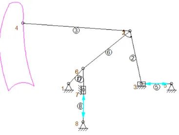
2.1 Kinematics of the linear actuated leg design. The pink curve shows the foot (point 4) trajectory. Blue arrows indicate the linear actu-ators’ directions. . . 9
2.2 Body, leg and joint design of the linear actuated robot. Holes in black circled area are where the actuators are connected to the body for a single leg. Red circled area is a leg’s foot where it touches the ground. . . 10
3.1 CAD drawing of the soft/hybrid robot assembly with 3D printed thermoplastic polyurethane (TPU) body and hourglass type poly-dimethylsiloxane (PDMS) legs. . . 12
3.2 The evolution of the body designs . . . 14
3.3 Conceptual leg mechanism and the trajectory of the foot. The motor position is assumed to be the origin. BD = 5.13 mm, CD = 19.49 mm, AC = 22.96 mm, DE = 32.76 mm, Constant Angle CDE = 105.84◦ . . . 15
3.4 The robot with PDMS body and PDMS c-shaped legs . . . 16
LIST OF FIGURES xiii
3.6 CAD drawings of cams: (a): old, (b): new . . . 18
3.7 Robot prototype with TPU body and PDMS ’composite’ legs . . 20
3.8 PDMS body fabrication (a: pouring of uncured PDMS into the mold, b: the final cured body after removal from the mold . . . . 22
3.9 PDMS c-leg fabrication (a: pouring of uncured PDMS into the mold, b: the final cured leg after removal from the mold . . . 23
4.1 CAD drawing of the hourglass leg. (Blue markers: joints, green marker: body connection, red markers: pin locations.) . . . 25
4.2 CAD drawing of the composite leg. (Blue markers: joints, green marker: body connection, red markers: pin locations.) . . . 26
4.3 Fabrication process for the hourglass leg . . . 27
4.4 Fabrication process for the composite leg . . . 27
4.5 COMSOL® simulations for hourglass and composite designs. . . . 29
4.6 A single frame from the side view video recording of the composite leg trajectory experiments. . . 31
4.7 The comparison of trajectories of the two different proposed mech-anisms and the simulation results with the rigid link/ideal pin joint assumption. The data is acquired through image processing. The motor positions of the leg mechanisms are taken as the origin. . . 31
5.1 The constructed CNC plotter for flexible PCB fabrication . . . . 36
LIST OF FIGURES xiv
5.3 PCB design with through hole components (a: etching process, b: component addition . . . 39
5.4 PCB design with SMD components (a: component addition) . . . 40
6.1 0.5 Hz walk gait locomotion of robots: (a): rigid , (b): soft . . . . 44
6.2 1 Hz walk gait locomotion of robots: (a): rigid , (b): soft . . . 44
6.3 1.5 Hz walk gait locomotion of robots: (a): rigid , (b): soft . . . . 45
6.4 Rigid robot climbing sequence at 1 Hz motor frequency . . . 46
List of Tables
Chapter 1
Introduction
It is pretty obvious that after the initiation of the Industrial Revolution in the 18th century, our technology has been advancing in an exponential manner. Many dif-ferent fields of research are growing non-stop ever since. Utilization of electricity enabled the rise of robotics; which can be seen as the ultimate field that will lead to what some people call ”Industry 4.0”, which mainly focuses on automation.
Automation of many different processes has started long ago. Some can be seen in the shape of a robotic arm that moves products from one place to another in a factory assembly line whereas some other can appear as a solo walking module that is used for transportation of materials, and many other forms can be seen in today’s immensely developing world. What is mainly common for all of them is the fact that they somehow are made of hard materials like metals and hard plastics. These are the sort of materials that most of the people (including myself) associate with electronics, robotics, and other high tech stuff. Computers, automobiles, and cellphones, for instance, are sort of obvious examples that come to my mind when I think of completely hard and stiff structures that involve electronic and mechanical components and can be related to robotics regarding their structures.
In my opinion, it is virtually impossible to get rid of the hard electronic compo-nents that practically give life to these machines; but their structural compocompo-nents do not necessarily have to be that hard. This is where ’soft robotics’ start at my mind.
Applications of soft robotics research right now mostly focus on the safe in-teraction with the environment, user and target. Furthermore, such soft robotics applications can be regarded to have much higher levels of adaptability in com-parison to their hard counterparts. Often, soft materials are integrated into rigid robotic parts to establish such interactions. On the other hand; untethered and complete soft robots aren’t that frequently seen, especially in the miniature scale. Such soft robots cannot exert high enough forces in order to implement unwanted damage on the mission environment or target objects as their structural elements would absorb most of that particular force. Besides, such robots have the po-tential to deflect their bodies, legs or other elements accordingly in order to pass through smaller openings than their cross-sectional areas or other absurd geome-tries. Examples of these robots either use soft materials or utilize hard materials in such a manner that they overall mimic softness. The concept of softness is still very subjective and classifying robots as soft is a major point of dispute. My work, on the other hand, considers softness in both behavioral and material terms.
1.1
Soft Robotics History and Applications
A relatively new field of research, what we know as soft robotics can be dated back to the 1990s; as most of the fabrication techniques [1] that construct the foundation of the soft robotics area has arisen at that time. Initial works of soft robotics can go back to 1970s, and today’s often seen soft grippers’ ancestors [2] were established at that time. However, virtually all of the examples of this field are from the 2000s and 2010s.
Soft robotics research mostly focuses on soft modules that are integrated into hard robotic systems instead of individual robotic modules. Soft grippers are frequently seen; and their one of the most famous versions utilizes granular ma-terials’ manipulation [3]. Some others also use pneumatic actuators in order to achieve the gripping [4]. Similar actuation principles are also seen at the in-dividual robotic modules (which can be tethered and untethered) as well but applications become significantly harder.
The softness of the robots is still a major point of dispute among soft robotics researchers. Some of the robots use elastomers and achieve softness through ma-terial usage [5], [6] whereas others are soft in behavioral terms although they’re made out of hard materials thanks to the logical management of compliant mech-anisms [7], [8]. A portion of the works done fall in the middle ground; as they can be somewhat referred to as ’hybrid’ robots joining hard materials with flexible components [9], [10].
Most of the soft robots in literature prefer shape memory alloys [5, 6, 11, 12, 13] or pneumatic actuators [10, 14, 15] to generate motion. Of the listed works, the SMA actuated robots are tethered due to high energy consumption, but moving the electronics outside of the robot means that the robots can be entirely soft. The pneumatic robots, on the other hand, have compressors or gas canisters that would make the robot somewhat hybrid. The work in [15] is a rodent exoskeleton run with pneumatic actuators and is tethered, but includes a rigid frame. Com-bustion is utilized as the actuation mechanism in [9], however, the researchers needed to include a hard core to the robot for necessary electronics and ignition mechanisms. As roboticists, we know how to make several components entirely soft, such as sensors [16] or even entire soft exoskeletons [17], but so far only one robot is reported as being entirely soft [18]. With the current status of soft robotics research, it is challenging to make an untethered and entirely soft robot, capable of locomotion.
1.2
Objective and Motivation
The motivation behind this work is to create a soft, untethered robot. The robot that is desired to be created is virtually not existent in the literature except for few examples [10] that show no sufficient resemblance. Some robots are made out of hard materials that are very similar in design [19] but their behavior is significantly different. This difference is my main piece of motivation, as at the very first place I wanted to see if robots that are almost identical in design but different in material are behaving similarly. To manipulate this difference in a useful manner is one of my main concerns, as due to their compliant nature, I expected soft legs to be much successful in rough terrain locomotion at the very beginning of this work. Also, this compliant nature of the structural materials used ensured a much higher shock absorption in contrast to rigid robots; mean-ing all components and any other possible cargo carried on the robot would be protected better. Finally, these soft components could also be manipulated with SMAs (shape memory alloys) in order to change their geometries; meaning that the legs and the body could be shrunk to pass through openings smaller than the robot’s cross-sectional area or any other irregular obstacle that could be en-countered during operation. This last part is still being researched in our lab as a future goal on this project by one of my fellow labmates.
I aimed to create this simple, yet capable miniature soft robot in order to show that such traits I’ve mentioned above could be utilized to use these soft robots in many applications their rigid twins aren’t very good at; like search and rescue under collapsed buildings, surveillance and data gathering in rough terrain mission zones, inspection of gas pipelines and so on. The robot I tried to create during research cannot be specifically assigned to any of these tasks at this point, but with the right sensors and other gear equipped; it can be easily converted to a task-specific module. What I did was merely creating the chassis on which the desired body and components can be placed.
1.3
Thesis Outline
This thesis is constructed with the following chapters:
Chapter 2 Design and Prototyping of a Soft/Hybrid Robot with Linear Actuators Made out of TPU (Thermopolyurethane)
An initial robot design that featured unified legs and body, each leg actuated by two linear actuators (servo motors with rack and pinion geartrains), prototyped using FDM (Fused Deposition Modeling) 3D Printing of TPU filaments. Joints are formed with geometrical differentiation instead of ideal pin joints.
Chapter 3 Design and Prototyping of a Soft/Hybrid Robot with DC Motors
The next design that featured separate legs and body, each leg actuated by a single DC motor (sub-micro plastic planetary gearmotor with a gear ratio of 700:1), prototyped using FDM 3D Printing of TPU filaments. This robot virtually has the same leg design with another robot from our lab, MinIAQ-II [20], except for the fact that the structural material used and joint designs are different. Joints are formed with geometrical differentiation instead of ideal rigid pin joints. The following step was to convert the DC motor actuated robot in terms of the material used, switching to PDMS. Switches in leg designs were also done at this phase.
Chapter 4 ’Hourglass’ and ’Composite’ Soft Joint Designs for Soft Mechanisms
At this point, my research also focused on designing and comparing two different completely soft joint designs that were to be used in the final robot. With different analyses and research, the work conducted here led us to publish a paper that proposed generalized soft joint design and fabrication procedures at IEEE Robosoft 2019 conference. The joint designs that were fabricated and compared were different in geometrical and material terms.
Chapter 5 Flexible Circuit Board Design and Fabrication
To achieve utmost softness and flexibility, a thin and flexible circuit board (except for the small hard components onboard) was attempted to be fab-ricated.
Chapter 6 Testing, Results and Discussion
After successful operation of the fully assembled robot with PDMS body and legs, a test robot (out of PLA) was constructed with an identical body and leg design in order to see the structural materials’ effects on locomotion and other aspects of robot motion.
Chapter 2
Design and Prototyping of a
Soft/Hybrid Robot with Linear
Actuators Made out of TPU
Very initially, different designs were considered to be selected as a starting point. In comparison to the other miniature robots fabricated in our lab, which are virtually all made out of PET (polyethylene terephthalate) sheets folded with origami techniques; the soft robot I wanted to design would have one very basic but significant difference: weight. Such PET sheet robots would be almost three times lighter in contrast to a soft copy according to the initial predictions, re-garding the densities of the structural materials. This canalized my main focus on making the robot in such a way that it’d be able to carry its own weight at the very first place. So that, we decided to kickstart our design process using linear actuators with high torques (rack and pinion mechanisms actuated by a very small servo motor).
2.1
Linear Actuators
The servo motors that were utilized were of the brand ‘Goteck GS-1502’, weighed 1.5g, worked between a voltage range of 3.7 to 5 Volts and could implement a torque of 80g-cm. Nevertheless, the torque value changed regarding the gear trains position so, with a proper locomotion mechanism, high torques could be implemented during the touch of the feet.
2.2
Joints and Locomotion Mechanism Design
Designing miniature robots out of hard materials is relatively easier but one specific part of the locomotion mechanism eliminates a big challenge that is en-countered in the soft design. Ordinarily, hard mechanisms benefit metal pins to create joints which are able to turn 360 degrees with ease, as the links that are joined at the pin are on different layers and completely independent of each other. Nonetheless, no such option exists for soft materials. Thus, geometrical differ-ences were utilized in order to create such joints. The places which are wanted to act as joints were fabricated much thinner in opposition to the rest of the links. Thanks to the elastic nature of the material employed; this created bending at those particular locations during the actuation of the leg mechanism.
The emerged design wields two linear actuators in order to drive the leg’s locomotion mechanism. The designed leg mechanism tries to imitate the walking motion of cats and dogs, creating a very similar coupler curve to those animals’ foot trajectories. The two different motors employed actuate the mechanism in two different axes; one of the motors drives the leg forward and backward in the plane parallel to the ground whereas the other one moves the leg in the vertical axis in regard to the ground.
Figure 2.1: Kinematics of the linear actuated leg design. The pink curve shows the foot (point 4) trajectory. Blue arrows indicate the linear actuators’ directions.
As two different actuators were used, combining them on a single and contin-uous link proved to be problematic. Driving both motors on the same layer was unfeasible as driven links would crash into each other. To solve this problem, the mentality behind ordinary rigid pin joints was used. Two different layers of links were created in order to drive them separately and independently with ease.
Figure 2.2: Body, leg and joint design of the linear actuated robot. Holes in black circled area are where the actuators are connected to the body for a single leg. Red circled area is a leg’s foot where it touches the ground.
In order to create this body-legs assembly as a whole, 3D printing of elastic filaments seemed like the most possible solution. Nevertheless, it proved impos-sible to be conducted due to a number of reasons like the very hard fabrication processes of elastic filaments, too many bridging and roof parameters of the body design which required the extrusion of support material and other complex ge-ometrical elements included in the design. Only one prototype was tried to be fabricated and this trial was unsuccessful. At this particular instance, molding of the design was also considered but wasn’t conducted as the same reasons would ultimately fail that trial too. Taking all of these problems into the account and furthermore, considering the need of two motors for each leg; this design was abandoned without further analyses.
Chapter 3
Design and Prototyping of a
Soft/Hybrid Robot with DC
Motors
After the linearly actuated legs and body design; the main concern about the new possible design became fabrication. This lead to a new design with separately fabricated body and legs, which are to be joined after curing is done. The leg mechanism designs for four-bar and c-shaped legs are discussed in this chapter, however, the joint designs and the final fabricated legs of the four-bar version are discussed in chapter 4.
The miniature robot design is modified from another work conducted in our lab, MinIAQ–II, a miniature foldable quadruped with individually actuated legs [20]. The soft version prototype with a TPU body and PDMS ’hourglass’ legs(which is to be explained in the following chapter) can be seen in Fig. 3.1. In this, soft/hybrid robot version, the kinematic design of the robot is kept, however the limitations on further miniaturization of the robot is eliminated by replac-ing the origami-inspired foldreplac-ing techniques used on PET sheets with moldreplac-ing of soft materials to achieve a very similar mechanism design. Another advantage of utilizing the soft materials is the possibility of changing the shape or the size of
the robot during operation using additional actuators to make the robot squeeze through small openings, if needed.
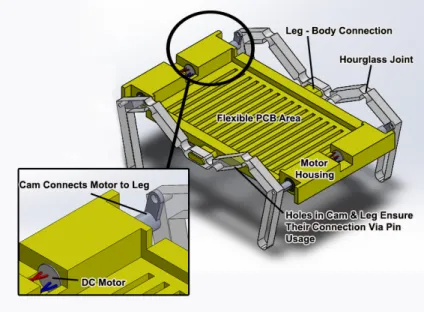
Figure 3.1: CAD drawing of the soft/hybrid robot assembly with 3D printed thermoplastic polyurethane (TPU) body and hourglass type polydimethylsilox-ane (PDMS) legs.
The robot design consists of two main components; the body and the legs. The body has a rectangular form with a total of four DC motor housings, two of them located at the front and the rest located at the back, whereas the middle section is reserved for the circuit board. Symmetric extensions from the right and left sides of the body’s middle axis connect the legs to the body. These extensions aren’t existent in the version with c-shaped legs. Two different structural materials are used for the production of the body and the legs; thermoplastic polyurethane (TPU), which is a 3D printable soft material, is used for the body and the legs are made out of PDMS using molding methods. Next versions also include PDMS bodies too.
3.1
The Body and The Electronic Components
The actuators used in this robot are selected as DC motors so that the design will stay simple and compact, and the robot can be untethered. Very small DC motors with plastic planetary gearboxes of 1:700 ratio (Pololu, 1:700 Sub-Micro Plastic Planetary Gearmotor) are selected to run the robot’s leg mechanisms. The motors chosen have relatively high-torque output in comparison to actuators that we use to run similar mechanisms in foldable miniature robots, mainly because the soft materials we used in the mechanism are much dense and accordingly heavy in comparison to light foldable materials such as PET sheets or cardboards. The motors are connected to infinite turn potentiometers (used as absolute rotary encoders) by 3D printed miniature cams. The data gathered from the sensors are utilized through closed loop controllers in order to constantly regulate position and speed of the legs.
Motor housings have bridging roofs which provide a complete enclosure of the motor in the TPU prototype. Nevertheless, in the PDMS version of the body there is no complete enclosure due to fabrication constraints of molding procedure. Dimensions are decided such that a slim fit connection between the motors and the body is achieved. At the endpoint of the motors, small openings are made for motor cable connections to the circuit board.
Middle of the body is covered with walls that are taller than the circuit board and the circuit elements in order to provide partial protection from surroundings. The top of the robot body is not covered for easy circuit or component removal. A linear pattern of lines constitutes the body’s main frame, with gaps between them. This is done in order to reduce the weight of the robot while preserving its structural integrity.
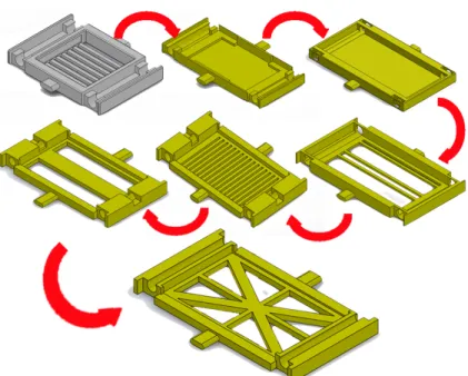
In the latter versions of the robot; the middle section’s design was evaluated in order to establish a balance between weight and structural integrity. Fig. 3.2 shows the evolution of these body designs. During testing, the version resembling the ’union jack’ seemed to be the most appropriate and efficient choice.
Figure 3.2: The evolution of the body designs
3.2
Fourbar Crank-Rocker Leg Design
The initial leg mechanism that was designed is a basic crank-rocker type fourbar linkage, with tip of the leg being an extension of the coupler link. The coupler curve is optimized by changing the link length ratios in order for the trajectory to resemble a D-shaped trajectory as much as possible. The flat side of this D shape is meant to be the downward half of the trajectory, which is the section where the leg touches the ground; and the curvy side is the part where the robot lifts its legs up into the air and steps forward. Normally, elliptic trajectories may also have been sufficient for walking motion. Nevertheless, as the flatness perishes from the section where the leg touches the ground, bumpier the motion becomes. This is a common issue for all miniature robots where the motion mechanism is chosen as a fourbar for simplicity. Unfortunately, there is no fourbar design with a partial straight-line in the downwards half of the coupler curve. (The closest is the lambda mechanism where the pseudo-straight line is in the upwards half of the coupler curve.) Therefore, the optimization comes as close to a D-shape as possible with a regular fourbar morphology. The resulting fourbar from this
Figure 3.3: Conceptual leg mechanism and the trajectory of the foot. The motor position is assumed to be the origin. BD = 5.13 mm, CD = 19.49 mm, AC = 22.96 mm, DE = 32.76 mm, Constant Angle CDE = 105.84◦
The main challenge going from conceptual design phase to detailed leg mecha-nism design is to ensure that the resulting legs will follow the projected trajectory from the conceptual design phase. The mechanism design and the correspond-ing trajectory is valid for perfectly rigid links and pin joints, which enable 360 degrees of rotation. However, soft materials were used for fabrication, meaning that the links will not be perfectly rigid. This forces us to come up with a joint design, in which the links are not perfectly rigid, but still as the mechanism is actuated from a cam, the rotational displacements in the mechanism occur at or close to the prescribed joint locations. Two different completely soft solutions to this problem are proposed at chapter 4.
3.3
C-shaped Leg Design
After the formation of the crank-rocker fourbar leg designs and their assembly onto the PDMS body, the body could stay on its feet when it was stationary.
However, when the legs were actuated from the cams and legs were lifted; it was realized that ground link disconnection resulted in severely absurd behavior of the body. As the legs were lifted, potentially infinite degrees of freedom were formed at that particular leg’s motor connection; causing the body to move in unexpected manner; meaning waver and tremble occurance instead of locomotion. During the experimented trot gait; the two legs on the ground weren’t able to carry the body because of this phenomenon.
Moreover, forcing a kinematic chain to a soft robot seemed to lose popularity among ourselves. In order to utilize the ’softness’ of the robot to the maximum possible extent; instead of forcing a kinematic chain, using simpler legs deemed to be a better idea. This way, the body could manipulate itself in obstacle crossing with more freedom in contrast to the other leg version. In other words, softness of the robot would be expressed and used more extensively.
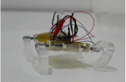
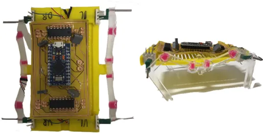
Figure 3.4: The robot with PDMS body and PDMS c-shaped legs
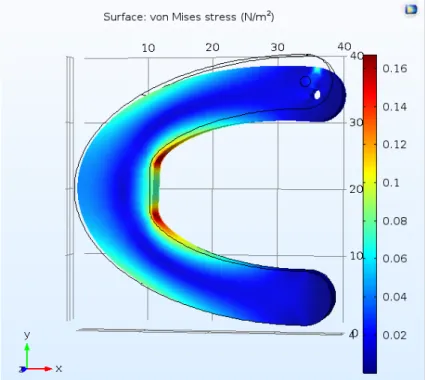
Both of the reasons given above lead us to design and fabricate specially de-signed c-shaped legs to be used for robot locomotion. In order to make the c-shaped legs strong enough to carry the robot’s weight; different thicknesses and radiuses were put to trial. COMSOL analyses were conducted in order to esti-mate what the dimensions of the leg should be in order to make four legs carry
four legs in order to see if they’d be able to carry the body. The leg with mini-mum possible thickness that carried the robot was chosen after evaluation of the analyzed different leg designs.
Figure 3.5: COMSOL stress analysis of a c-shaped leg version
3.4
Cam Design
Connecting the designed soft legs to the motors proved to be a challange due to the differences between motor and sensor dimensions. The rotary encoders (that are used as sensors to read/control position and speed of the legs) have an opening that is identical in shape to conventional NEMA-17 motor shafts (which are D-shaped with approximate shaft radius of 5 mm). On the other hand, the Pololu gearmotors used in our robot only have a shaft diameter of 2 mm. A connection part which would be linked to both of these parts and the leg was needed to be designed and fabricated.
During the crank-rocker leg design phase, a cam that was connected to the leg with the help of a pin was utilized. The inner diameter of the cam would be equal
to the motor shaft and the outer diameter was the same with the rotary encoder. Nevertheless; this design couldn’t be used with the c-shaped leg, as there was no mechanism left to make the pin stay in its place. In the crank rocker design, the pin couldn’t turn around its axis as it was forced by a kinematic chain. With the c-shaped leg, however, no restriction of motion made the pin turn around itself instead of turning the leg. This emerged the need to design a cam that would be unified with the c-leg.
The new cam design was much longer in comparison to the earlier one, and it was to be inserted inside the leg’s mold. After pouring of the PDMS, it would be encapsulated in the leg. The part that wasn’t emerged in the leg was very similar to the earlier design; with an outer diameter with the dimensions of the encoder and inner diameter with the dimensions of the motor. In order to establish a sufficiently strong connection between the motors and the cams; incremental amounts of CA glue was applied inside cams before connection.
(a)
(b)
3.5
Fabrication
Fabrication can be seen as the biggest challenge to be tackled in case of this robot, especially because the curing of different elastomers (which are discussed in chapter 4) to create a working mechanism as we describe here has not been reported in literature. We have two main methods of fabrication which are 3D Printing of flexible filaments and molding of polymers into 3D Printed hard plastic molds. For all 3D Printing purposes; we use a Prusa MK2S FDM Printer.
This section discusses the methods that are used for fabrication. The body’s and the c-shaped legs’ fabrication are also discussed in the following subsections. As specialized joint designs are done with the crank-rocker fourbar linkage leg, its fabrication is described in chapter 4.
3.5.1
3D Printing of Flexible Filaments for Prototyping
Printing of flexible filaments is a challenge, especially with complex geometries like our robot’s body. This is due to the problematic retraction properties of the flexible filaments. Most of the 3D Printing applications worldwide are done by usage of hard plastic filaments; PLA (Polylactic Acid) and ABS (Acrylonitrile Butadiene Styrene). FDM printers retract the filament that is being deposited through the nozzle during travel in order to prevent phenomena such as webbing, stringing, and over extrusion. Hard plastic filaments like PLA and ABS are easily retracted, whereas flexible ones tend to buckle up during this process as they can easily find a less resistant path among the way up. To overcome this, we specifically set up the speed of the printer nozzle for all print moves to 15mm/s, much slower than the default value. We also reduced retraction and modified the printer head to increase the tension on the filament. Printing temperature was kept at 195◦C. Talc powder was applied on the printing bed prior to the print for easy removal after the process is done. The same printer was also used for the fabrication of PLA molds.
Figure 3.7: Robot prototype with TPU body and PDMS ’composite’ legs
3.5.2
PDMS Molding
Fabrication of the legs from elastomers are done using molding techniques, which is often classified under soft lithography methods [1]. PDMS Sylgard® 184 man-ufactured by Dow Corning was used to form the PDMS network. The kit consists of two components: pre-polymer (base) and cross-linker (curing agent). As a gen-eral procedure; the two components were mixed in a plastic beaker and degassed by keeping the mixture under vacuum for 15 min. The degassed mixture was poured into the PLA molds produced by 3D printing. The manufacturer recom-mends to mix the base and curing agent with the 10:1 weight ratio. However, studies showed that the mechanical properties such as stiffness of the final PDMS material depend on the mixing ratio of the components [21, 22]. Thus, increasing the amount of the cross-linker led to the stiffening of the PDMS network, e.g. elastic modulus of PDMS cured with ratio 5:1, 7:1, 10:1 (base / curing agent) was found to be equal to 3.59, 2.91, 2.61 MPa, respectively [22]. In our case, the PDMS network of hourglass leg should characterize with a higher stiffness in or-der to hold the body, but in the same time it should be elastic enough to bend at the joint locations. Thus, three mixing ratios of 5:1, 7:1, and 10:1 were examined
components mixed with ratio 10:1 turned out to be too soft to hold the body. However, promising results were obtained for the legs made of PDMS cured with 5:1 and 7:1 ratios. Due to the difficulties during the release of PDMS leg (ratio 5:1) out of the PLA mold, PDMS cured with 7:1 weight ratio was used to fab-ricate the hourglass legs. Still, releasing the leg from the mold was conducted carefully, because hourglass shaped joints were vulnerable.
The PDMS curing process can be explained in a step by step manner. Initially, the base and the curing agent are mixed in a plastic cup thoroughly. Following, in order to eradicate the air bubbles, the mixture was put in vacuum owen. Before the mixture was poured into the PLA mold; the mold was coated with Ease Release 205® (by Smooth-On® )in order to ensure the easy removal of the cured PDMS mixture. Next, the uncured mixture was poured into the mold with the help of a syringe and the mold was kept in an owen at 70◦C for a total of 4 hours in order to fasten the curing process. Finally; the mold was removed from the owen and in order to conclude the curing; it was kept in room temperature for another 18 hours.
3.5.3
Body Fabrication
For the fabrication of the body; PDMS Sylgard®184 polymer was cured with 10:1 (base / curing agent ratio). The highest possible ratio was promoted in order to enable the body go through buckling motions as much as it could. In comparison to the legs, which are fabricated with 5:1 ratio; the body was fabricated in the most flexible fashion possible. Relatively harder legs already had ensured the desired posture of the robot; and in order to take the advantage of the softness as much as we could; the body was fabricated in the softest manner possible.
The mold was 3D printed using PLA filaments. Due to the restrictions molding process has by nature; two steel rods with the diameter of the motors were inserted inside the mold from two openings. These rods ensured the motor housings would form by preventing PDMS flow to those particular areas. After complete curing, these rods are removed in order to open the motor housings.
Figure 3.8: PDMS body fabrication (a: pouring of uncured PDMS into the mold, b: the final cured body after removal from the mold
3.5.4
C-Shaped Leg Fabrication
The c-shaped leg fabrication was also done using the PDMS Sylgard® 184 poly-mer, but in contrast to the body; 5:1 (base/curing agent) ratio was used in order to make the legs rigid enough to carry the body.
The mold includes a small groove for cam placement as an extra. PLA cams are inserted in these grooves and they act as strong connection elements between the motor and the leg after the curing of the PDMS is complete.
PDMS curing is done almost identically with the body; except for the PDMS ratio. Again, the two agents are mixed in a plastic cup. Then, they’re put inside a vacuum owen for air bubble removal. The mold is again treated with Ease Release 205® (by Smooth-On® ). After pouring of the mixture inside the mold; it’s kept in 70◦C owen for 4 hours and outside at room temperature for 18 hours.
Figure 3.9: PDMS c-leg fabrication (a: pouring of uncured PDMS into the mold, b: the final cured leg after removal from the mold
3.5.5
PLA Cam Fabrication
The PLA cams which connect the body and the motors are 3D printed using PLA filaments. As the dimensions of this cam are very small and extreme precision is needed; all print speeds were decreased to 20 mm/s from the default of 50 mm/s. Also, 0.1 mm layer heigh was employed (default is 0.2 mm). In order to have minimum stringing and other retraction related issues, print temperature was reduced to 190◦C from the default of 215◦C.
Chapter 4
’Hourglass’ and ’Composite’ Soft
Joint Designs for Soft
Mechanisms
The work expressed here is from our IEEE Robosoft 2019 paper ’Joint Design and Fabrication for Multi-Material Soft/Hybrid Robots’ [23]
4.1
’Hourglass’ Joint Design
The initial joint design proposal, which we refer to as the ’Hourglass’ version, is named after it’s joints’ resemblance to hourglasses, as shown in Fig. 4.1. The leg mechanism is composed of the same material (PDMS) all along but its geometric properties are variant among different sections. The design is such that the joint locations are like thin features of an hourglass whereas links are much thicker. So that, the mechanism tends to deform from the joint locations due to the difference of mechanical compliance at the links and the joint locations. The rotational input given to the crank of the mechanism provides bending at
calculated trajectory is observed.
Figure 4.1: CAD drawing of the hourglass leg. (Blue markers: joints, green marker: body connection, red markers: pin locations.)
4.2
’Composite’ Joint Design
Despite functioning properly, the hourglass joints tend to tear easily during fab-rication process, which lead us to believe that the mechanical stress on the joints during the operation might also easily break the joints. In order to solve the fab-rication issues and potential joint weakness another design is proposed. In this other design the links have the same dimensions and they are made of PDMS, the same structural material that is used in the hourglass design. However, the structure thickness stays the same for both the links and the joints in this version. Instead, we differentiated the materials used for the link and joint locations, as shown in Fig. 4.2. Joints were made up from a much softer version of the mate-rial we used for the links (commercially known as EcoFlexTM) in order to make
them significantly more compliant in comparison to the links. When actuated, the trajectory observed showed strong resemblance to the calculated trajectory.
Figure 4.2: CAD drawing of the composite leg. (Blue markers: joints, green marker: body connection, red markers: pin locations.)
4.3
Fabrication
Part A and B of EcoFlexTM 00-30 (Smooth-On), which is used in the making of
the composite leg was mixed 1:1 in a plastic beaker and degassed at vacuum after mixing. To enhance visualization of the EcoFlexTMparts, Silc Pilg Red
(Smooth-On) dye was used. The following processes were used for the fabrication of the two different leg designs:
4.3.1
Hourglass Leg
PDMS Sylgard® 184 was mixed in a 7:1 ratio of a pre-polymer and cross-linker and mixed very well in a plastic cup. After that, in order to get rid of the air bubbles, the mixture was placed in a vacuum oven. Using syringe the PDMS was poured into the PLA mold and placed in the oven at 70◦C for one hour (Fig. 4.3a). Then, the mold was kept at room temperature for 18 hours to finish the curing process (Fig. 4.3b).s
Figure 4.3: Fabrication process for the hourglass leg
4.3.2
Composite Leg
Using a syringe, the PDMS mixture, prepared the same way as described in section 4.3.1, was poured into the PLA mold and placed in the oven at 70◦C for one hour.
Figure 4.4: Fabrication process for the composite leg
To be able to pour EcoFlexTM into the mold, we designed puzzle blocks in
the joint locations (Fig. 4.4a, b). These blocks prevented PDMS from leaking to joint locations and were removed from the mold after the curing process was completed (Fig. 4.4c).
After PDMS was cured for an hour, the puzzle blocks were removed and EcoFlexTM 00-30 (previously mixed in a 1:1 weight ratio of part A and part
B, and Silc Pig® Red, manufactured by Smooth-On) was poured into the joint locations. The mold was kept at room temperature for 18 hours to let the curing process finish. Fig. 4.4e suggests that EcoFlexTM did not considerably diffuse
into the PDMS matrix during curing and both PDMS and EcoFlexTM remained
as joined but separate material domains.
4.4
Joint Simulation and Experiments
Once the hourglass and composite leg mechanisms are fabricated, they are as-sembled with the 3D printed TPU robot body and connected to the motors via the 3D printed cams for experiments. We want to achieve a trajectory similar to the one acquired at the conceptual design phase, however we also would like to know which leg design is preferable. Since the failure of such a mechanism is expected to occur at the joint locations, we would like to know which joint design would have lower mechanical stress during a similar deformation. Higher mechanical stress at the joint locations might lead to instant failure due to high loads as well as earlier failure from fatigue.
In order to find the stress levels experienced in the two designs, a finite element model of the two joints are built in Comsol environment. To show that the legs follow an acceptable walking trajectory, experiments are run with both designs and the foot trajectory is tracked. The two designs are also run for 250.000 cycles to see if the mechanisms would undergo fatigue failure or the composite mechanism would delaminate from the locations where two different materials are combined.
4.4.1
Finite Element Simulations
are connected with an hourglass PDMS joint, in the other, two PDMS links are connected with the same thickness EcoFlexTM joint. For the designs, we tried to
keep the rotational stiffness of the joints the same, i.e. the two designs would bend the same amount under the same applied moment. Following, we imported these to the COMSOL Multiphysics medium. We used the solid mechanics toolbox to conduct a time dependent study. A total distributed force of 0.001 Newtons was applied for 10 seconds at the rigid link above the joint location. Extremely Fine physics-controlled mesh was used for both cases. All other boundaries are set to be free except for the base, which is fixed.
(a) COMSOL® simulation for the hour-glass design.
(b) COMSOL® simulation for the compos-ite design.
Figure 4.5a shows the FEA results for the hourglass type joint and the Fig. 4.5b shows the results for the composite type mechanism. Hourglass mechanism has an average stress of 8.008 Pa along the horizontal centerline of the geometry whereas the composite design undergoes an average stress of 1.977 Pa at the same line. Furthermore, the maximum stress values are 20.262 Pa for the hourglass design and 7.323 Pa for the composite design accordingly. Both the average and maximum stress values are found by taking the average of all instants for 10 seconds. Results show that for the hourglass version, the stress is not localized and is relatively widespread. On the other hand, although the composite version undergoes localized stress at certain locations, the magnitude is much lower than the hourglass version. In fact, the maximum stress in the composite version is smaller than the average stress in the hourglass version. This result suggests that a possible failure of the leg is much likely to happen with the hourglass version.
4.4.2
Trajectory Experiments
To observe the trajectories of the two leg designs, we attached the legs to a TPU, 3D printed body, connected the motors to the legs and actuated the mechanisms. During these experiments, side view video of the legs are recorded and the position of the feet are tracked using simple image processing techniques. A total of ten cycles are done with each leg specimen and approximately ten points are taken by image processing for each cycle. All of the acquired points from the experiments are shown in Fig. 4.7. A screenshot from these experiments is shown in Fig. 4.6.
The experimental process we used is straightforward. Initially, tips of the legs were colored blue. Then, the linkage was driven and the motion of the leg was recorded in front of a green screen. Later, the video file was imported to MATLAB® environment. For the whole length of the video, each frame was read separately. These separate readings were thereafter filtered through a basic if loop in order to only preserve pixels with significant blue values. Each filtered frame’s centroid was found and its coordinates were preserved in a matrix. After all
Figure 4.6: A single frame from the side view video recording of the composite leg trajectory experiments.
trajectory. This process was repeated for both of the legs proposed in this paper. In addition to the experimental results, the expected trajectory from the fourbar mechanism with the rigid links and ideal pin joints assumption is also shown in Fig. 4.7.
Figure 4.7: The comparison of trajectories of the two different proposed mecha-nisms and the simulation results with the rigid link/ideal pin joint assumption. The data is acquired through image processing. The motor positions of the leg mechanisms are taken as the origin.
The experimental results show no considerable difference between the two mechanisms. However, the hourglass mechanism seems to have a wider trajec-tory whereas the composite mechanism has a smoother trajectrajec-tory. Both of the
trajectories generated by the soft mechanisms are slightly larger than the simu-lated trajectory of the fourbar with same dimensions but rigid links and ideal pin joints. The difference between the simulated results and the experimental data can be attributed to the elasticity of the links. We can also visually observe that the links extend and contract slightly during operation.
4.4.3
Cyclic Runs
Another experiment we ran was driving each of the different leg mechanisms for three days continuously at 1 Hz drive frequency to see if they would undergo any fatigue failure. Such experiments correspond to about 250.000 cycles of op-eration. Other than the fatigue, we were also worried that the composite legs’ material changing interfaces might delaminate; as we thought that sudden (virtu-ally discontinuous) change in the material and accordingly the Young’s Modulus would be problematic. Therefore, a test setup was constituted with utilization of a camera and a power supply. The motors driving the leg mechanisms were powered continuously while the camera captured snapshots of the legs every ten minutes. Results show that neither one of the legs would fail from fatigue nor would we able to observe any crack formations. Hence, we concluded that both of the joint designs can be utilized in a soft robot for long term operation.
Chapter 5
Flexible Circuit Board Design
and Fabrication
Because of the facts that the robot body is big enough and fabricating a flexible circuit board with SMD components would be much harder; a flexible circuit board fully equipped with through-hole components was initially designed and planned to be fabricated. In order to achieve flexible circuit boards, double-sided copper-clad polyimide sheet of brand DuPont with polyimide thickness of 25 µm and copper thickness of 35 µm was decided to be utilized.
5.1
Fabrication Means: CNC Plotter
Construc-tion
To fabricate such a board that required an alternative method, the inaugural effort was to design and use the process of CNC Isolation Track Milling. How-ever, this procedure was viable in thick materials like FR-4 and the early trials with this method showed that the drill bit employed would easily damage the polyimide sheet, which is very exposed to shearing and laceration. Due to this huge disadvantage , CNC Isolation Track Milling procedure was abandoned.
The other system that was taken into account was the CNC Plotting procedure. With this method, all circuit traces, pads, vias or any other possible circuit part is drawn on the blank copper-clad polyimide sheet with the help of a three-axis CNC plotter equipped with a permanent ink pen. The ink of the permanent pen acts as a masking agent for the following etching procedure. Any drawn shape or trace is protected from the acid solution by the ink of the permanent pen, while all other areas which are left open are exposed to acid and etched. After the procedure is finalized, only desired traces and shapes are left as copper on the polyimide sheet.
For this purpose, a three-axis CNC plotter was constructed. An open-source CNC Plotter project was modified in accordance with our needs and was con-structed correspondingly.
5.1.1
CNC Plotter Components and Software
The machine consists of 3D printed PLA connection parts (fabricated using a Prusa i3 MK2 FDM 3D Printer), two NEMA-17 stepper motors which provide motion for the X-Y axes, which are the axes that are parallel to the ground and form the plane on which the copper-clad polyimide sheet is laid on. The third axis, Z axis, is controlled by a miniature servo motor of brand Tower Pro SG90. This axis is where the permanent pen (Edding 140S) is equipped, and it is lifted up and down depending on the desired geometry. All of the motors are controlled by an Arduino Uno outfitted with a CNC shield. A DC power supply is used for powering up the whole machine and a small fan is implemented for controlling overheating of the motor drivers on the circuit board.
The plotter takes g-code files as inputs, and as the communicating software, Source Rabbit G-Code Sender is used. The plotter’s circuit board is connected to a PC using a USB cable. The g-code sender utilizes this connection to send the code to the machine. In addition to the input g-codes, manual control of the
Generating the g-code from the circuit board’s drawing (which was done in Autodesk EAGLE ) proved to be a bit problematic. First, a freeware vector graphics software named Inkscape was utilized. The circuit drawing exported from EAGLE was imported to Inkscape. However, Inkscape couldn’t detect the circuit traces as vectors but as a pixel-based picture. This led the g-code to be generated from Inkscape to have contours on the edges of the traces but not on the trace itself. Regarding this fact, the exported circuit drawing was imported to Adobe Illustrator prior to Inkscape, in which it was converted to vectorial format. Every trace, pad, via or any other shape was converted to vectors and they were grouped together. The result was a vectorial lines cluster with gaps inside the traces. In order to fill these gaps, Inkscape’s Eggbot Hatcher extension was used.
With the use of this method, the desired circuits could be drawn on the copper-clad polyimide sheets but too many switches between different software were needed. This created confusions and mostly resulted in some user errors which lead to incorrect boards. Furthermore, the Eggbot Hatcher extension spent too much time and slowed the whole process. Taking all of these into the account, alternative software were searched and FlatCAM was decided to be utilized. This program is also used in CNC Isolation Track Milling method and is very user-friendly as it is solely designed to fabricate PCB boards. Earlier, .dxf input was exported from EAGLE and was tried to be vectorized using several different software. Notwithstanding, as FlatCAM takes .gbr (Gerber) files as input and EAGLE can output these files, the whole process is conducted with ease. Thanks to this feature, all different elements on the circuit board could be distinguished and modified in the desired manner. As the traces were now defined as a single line; the plotting process was concluded faster and with more precision.
The tip of the pen was the final factor that affected the precision of the drawing. Different pens were tested and examined. The most important criteria were how strong the bonding of the ink to the copper and how thin the tip of the pen was. Initially, Artline Drawing System and Pigma MICRON pens, both with 0.1mm tips, were tried yet their ink bonding proved to be not sufficient enough. So that, although they had the thinnest possible tips among all the pens available
in the market, they were not used. Several different trials with 0.3-0.4 mm tip pens showed that Edding 140S produced the best results. This pen was used as the masking agent for the etching process.
Figure 5.1: The constructed CNC plotter for flexible PCB fabrication
5.2
G-Code Generation
After importing gerber files from EAGLE , the following steps in FlatCAM are followed to create the g-code that is to be input to the CNC plotter:
Step 1: Install FlatCAM 8.909 BETA Edition.
Step 2: File → Open Gerber (with Follow) → Copper Top. Repeat for Soldermask Top and Profile.
Step 3: From project tab, select copper top.gbr. Go to selected tab, click ’Follow Geo’, then click ’FULL Geo’. All of the lines should be red now. Repeat for profile.gbr and soldermask top.gbr.
Combo SimpleGeo from geometry subtab and right click → disable plot. Select Combo SimpleGeo, go to selected tab, adjust Feed Rate X-Y to be 400 and click generate. Every trace should be blue now. Click Save CNC code, save as a text file (.txt).
Step 5: For two sided PCB, repeat all steps but after importing gerber files, select them all and Options→Flip on X Axis.
5.3
Etching Procedure
For the etching procedure, initial trials were done with FeCl-HCl solution as it was known to not release any gases and produced a relatively safe chemical reaction. However, this solution created a fairly slow reaction and at times didn’t produce desired results in terms of the removal of the copper layer. So that, a new, efficient but non-hazardous, solution was searched. After this search, a new solution involving hydrogen peroxide was decided to be utilized. This solution involves 1 unit 17% concentration hydrochloric acid, 1 unit 50% concentration hydrogen peroxide, and 3 units of pure DI water. The reaction between this solution and the copper-clad polyimide sheet is exothermic and convects heat to surroundings. In order to control this heat; the reactants are put into the beaker with the order of hydrogen peroxide first, pure water second and hydrochloric acid third. After pouring of all the reactants, the beaker is placed under a fume hood and the copper-clad polyimide circuit board is inserted in the beaker with the help of a long tweezer with plastic coated tips (the plastic coating is for preventing the tweezer to scratch the board and also prevent etching of the tweezer itself). In approximately a minute; the reaction produces oxygen bubbles. It is observed that these bubbles float the circuit and they cause non-uniform etching of both sides. To prevent this, the circuit is turned using the tweezers approximately every 5 seconds. Depending on the size of the board, 3-4 minutes later polyimide layer starts to be visible. After this instant; the etching process fastens dramatically and in order to prevent over-etching; extreme caution should be employed.
After etching is finished, the board is cleaned with tissue paper. After all of the acid solution is cleaned; the permanent marker ink that masked the traces is removed using acetone. As a last step, pads and vias are drilled with a small drill bit.
5.4
PCB Designs
Figure 5.2: PCB designs (a: through hole version, b: SMD version)
5.4.1
PCB Version 1: Through Hole Components
Initially, as the robot body’s dimensions were large enough and it’d be very diffi-cult to produce a board with SMD components with the CNC Plotting method; the fabrication of the PCB was conducted with through-hole components.
order to prevent any instantaneous voltage fluctuations and other phenomena like back-emf. Four infinite turn, absolute rotary encoders of brand Bourns 3382 were placed on the board, to be connected to the motor cams, were placed on the board in order to control the speed and position of the motors. Pololu 700:1 Sub-Micro Plastic Planetary Gearmotors, with high torques, were used for actuation.
During board generation using EAGLE , manually all traces width was in-creased to 0.3 mm, which is the thickness of the tip of the permanent marker used. Due to this change, autorouter generation of the traces was also modified; leading to irregularly shaped traces.
These PCBs appeared to be problematic due to several reasons. The copper traces weren’t uniform due to the nature of the etching process, and they tended to break and crack after flexing of the board. In addition, the relatively low resolution (due to the permanent marker’s tip thickness) resulted in too many shorts between the traces, which had to be cleaned manually by hand. All vias and holes in pads were also drilled manually and therefore; the whole process increased fault chance due to human error. Although some circuits worked for a limited time, none of the fabricated circuits proved to be reliable for longtime use.
Figure 5.3: PCB design with through hole components (a: etching process, b: component addition
5.4.2
PCB Version 2: SMD and Through Hole
Compo-nents
Due to the problems with the initial version of the PCB and regarding the time spent on PCB fabrication, the decision to order flexible circuit boards from a PCB manufacturer was made. Our lab’s generalized control schematic was employed for this fabrication (it wasn’t used in the earlier version as the plotter fabrication method couldn’t meet the resolution requirements). The advantages of these boards in comparison to the earlier version are the following:
Figure 5.4: PCB design with SMD components (a: component addition)
Higher trace width resolution
Copper surfaces emerged in polyimide films from both sides Pre-drilled vias and pads
Also, an SMD switch and pads for 3.7 V to 5V regulator were included, as the new boards had more empty space because of having thinner traces.
Chapter 6
Testing, Results and Discussion
In order to create a complete work, an identical version of the robot in design, but different in material (so that it becomes rigid) was also fabricated as a test robot. The test robot has body and legs made out of PLA, an FR4 circuit board which is also identical in design with the flexible board on the soft version. All of the electronic components are the same except for the motors. The motors used in the rigid test robot have 136:1 gear ratio whereas the motors on the soft robot have 700:1 gear ratio. This is due to two different reasons. First is that there is a significant weight difference between the two robots; as the soft robot weighs a total of 62.03 grams whereas the rigid robot is only 55.36 grams. The 136:1 gear ratio motors used on the rigid version aren’t able to lift up the soft version at all. Also, if the 700:1 gear ratio ones were to be used on the rigid version, the exerted forces on the ground by the legs would be somewhat too high in comparison to the soft legs (which act as dampers during the touch of the foot). This may have lead to potential damage to the robot components. The second reason is that these motors are very hard to come across in the Turkish market; and their import time is very long. This lead us to use the already existent 136:1 gear ratio motors on the rigid test robot; since the sufficient number of 700:1 gear ratio motors wasn’t existent.
For control purposes, the ’MinIAQ Gait Synchronization Control Algorithm’ by Mohammad Askari, Chulhyeong Lee and Alper Yeldan motor control code, which was developed and written in our lab, was adapted and used in accordance to our robot control needs. Walk (amble) gait was employed for all experiments. This gait has 90◦ difference between every different motor. When the front two motors are at 0◦ and 90◦; the ones at the back of the robot are at 180◦ and 270◦.
Two different types of experiments were done; straight walking and obstacle clearance. All experiments were done in front of black and white striped back-ground in order to measure the speed of the robots.
6.1
Straight Walking
Utilization of the same motor driver (L293DD) on both robots’ circuits required us to find the frequency intervals that the different motors on the robots could be actuated. For instance; the 136:1 motors on the rigid version cannot be ac-tuated at frequencies lower than an approximate of 0.5 Hz, whereas the 700:1 motors on the soft version cannot pass 1.5 Hz. So that, three different frequen-cies that could commonly be acquired in these two types are motors are chosen for experimentation. These frequencies are 0.5 Hz, 1 Hz and 1.5 Hz.
0.5 Hz 1 Hz 1.5 Hz
Rigid Robot 1 bodylength/sec 1.5 bodylengths/sec 2.18 bodylengths/sec Soft Robot 0.77 bodylengths/sec 1.37 bodylengths/sec 1 bodylength/sec
Table 6.1: Speed comparison of rigid and soft robots at 0.5 Hz, 1 Hz, 1.5 Hz
At 0.5 Hz; the rigid version has a speed of 1 bodylength/sec whereas the soft version only has a speed of 0.77 bodylengths/sec. At 1 Hz, these values become 1.5 bodylengths/sec and 1.37 bodylengths/sec, respectively. Finally, at 1.5 Hz; the values become 2.18 bodylengths/sec and 1 bodylength/sec. As it can be clearly observed; the locomotion of the rigid version is faster at all different motor actuation frequencies. There is one potential reason behind this; as the