IC
ON
A
RP
ICONARP
International Journal of Architecture and Planning
Volume 2, Issue 2, pp:59 - 72
ISSN: 2147-9380
available online at: www.iconarp.com
Jour na l of A rc hite cture a nd Pl an ni ng
Abstract
Climate change has drawn the attention of many researchers and practitioners to focus on the methods to address the challenges in achieving low-carbon buildings and cities and in future developments. Nevertheless, few studies have explored the impacts of thermal mass applications for the lowest carbon emissions of building operational energy consumption. A comparative study of CO2 emissions due to
different wall and floor compositions is presented in accordance with their lifespans for a hot-humid climate site. Aim of this study is to
Impact of Thermal Mass
Oriented Measures Over
CO
2
Emissions Of a
Thermally Insulated
Low-rise Apartment Building
in Izmir, Turkey
Mümine Gerçek
Zeynep Durmuş Arsan
Keywords:
CO2 emission, thermal mass, energy efficiency, housing
Mümine GERÇEK
İzmir Institute of Technology Department of Architecture İzmir, [email protected] Zeynep DURMUŞ ARSAN Dr.
İzmir Institute of Technology Department of Architecture İzmir, [email protected]
Jour na l of A rc hite cture a nd Pl an ni ng
60
examine the relation between the energy oriented operations andcarbon emissions of the building. Firstly, an existing low-rise building in İzmir is selected, then modelled in the dynamic simulation model software DesignBuilder v4 by synchronizing drawings with basic operational principles of the program. Furthermore, various influence factors of building envelope thermal characteristics are selected as follows: type, location, thickness and thermal specifications of materials used by keeping thermal conductivity value constant. At the end, the research presents remarkable influence of thermal mass oriented measures on reducing energy demands and carbon footprints.
INTRODUCTION
In many countries, energy consumption of buildings is 25–40% of the total energy consumption, in which most of the energy is used for space heating or cooling (i.e., air-conditioning) of buildings (Zeng et al. 2011). The huge energy consumption for heating or cooling buildings not only demands valuable fossil fuel resources, but also emits a huge amount of CO2 and other pollutants into the atmosphere. In fact, studies related to energy efficient buildings are of great importance all around the world. For example, Turkey paid $60.1 billion for energy exports and the dependence on foreign energy sources reached 72% in 2012, based on data from the Ministry of Energy and Natural Resources (MENR) and Turkish Statistical Institute (TUIK). Annual average energy demand saw an increase as 4.6%, while remaining at 1.6% in EU member states after the 1990s (Düzgün and Kömürgöz 2014). This creates the energy oriented approach where minimization of energy consumption is the main target. When the amount of CO2 released in building is the main indicator for reaching sustainability, the energy measures taken for achieving required heat transmittance coefficient (U) value may contradict with the targets for minimization of CO2 emissions.
There are different ways to reduce mechanical energy needs of buildings, which are shading, control of daytime ventilation, and use of better thermal mass qualities (CIBSE TM 36 2005). This paper focuses on thermal mass which is related with the heat gain of a building.
In buildings, thermal mass is typically provided by heavyweight materials such as full brick, stone and earth-based materials. Although inclusion of thermal mass through material type has thermal benefits, it is essential to compare them in order to investigate better options. For example, the impact of thermal mass on thermal performance of several types of Australian residential constructions was examined numerically using the AccuRate energy rating tool (Gregory et al. 2008). The performance of each construction type was evaluated using four different hypothetical building envelopes, referred to here as
Jour na l of A rc hite cture a nd Pl an ni ng
61
building modules. It was found that thermal mass had a dramatic impact on the thermal behaviour of modules studied, particularly in those where thermal mass was within a protective envelope of insulation. The reverse brick veneer and cavity brick constructions were found to be the most effective walling systems in this regard. Byrne and Ritschard (1985) analysed thermal mass effects on annual heating and cooling loads for three types of exterior walls including insulation placement and U value variations in 12 climates belonging to different cities of the USA. The study highlights that heating and cooling loads decrease due to various interactions between parameters affecting thermal mass. Later on, studies on construction materials with regard to life-cycle assessment and CO2 emissions as energy efficiency criteria are also included into researches (Fernandez 2008). The actual building was being constructed in concrete, and two further versions were hypothetically designed with steel or timber structures and finishes. Both energy use and CO2 emissions have been assessed over three main stages: initial production of building materials; operation of building; and refurbishment and maintenance of building materials over building's effective life. DesignBuilder was used to estimate whole life-cycle energy used and CO2 emitted in the operation of buildings over a period of 60 years. The results indicated that operating CO2 emissions were majority of life-cycle CO2 emissions, instead of total embodied emissions.
Researches explained, yet, do not fulfil the need for focusing on relation between thermal specifications and carbon emissions of residential buildings in Turkey. Thus, the specific objective of present study is to investigate how thermal mass as an energy oriented measure influences building behaviour and CO2 emissions. Furthermore, this investigation allows determining the effects of low carbon building design on heat absorption capabilities of building surfaces.
A flat located in thermally insulated low-rise apartment building in Izmir is used to investigate how different materials influence building thermal behaviour and environmental performance. Seventeen scenarios are developed over the modifications of thermal mass characteristics through which insulation layer placement, material type, location and thickness are combined for floor, partitions and exterior walls. In order to compare like with like, the overall conductance-area product (UA) is kept the same for different comparison scenarios.
PHYSICAL IDENTIFICATION Weather Data
The study has been carried out in İzmir, the west coast of Turkey (38.5°N latitude and 27.02°E longitude). The climate for
Jour na l of A rc hite cture a nd Pl an ni ng
62
studiedarea (İzmir) is hot-humid climate, labelled with Csa (Cs-for dry summer, a-(Cs-for hot summer) in the Köppen climate classification, referring to Mediterranean climate. Thus, the proximity to the Aegean Sea makes summer and winter temperatures relatively temperate, while summers are hot and dry in contrast to mild and rainy winters. July and August are the hottest months of summer, as well as January and February are the coldest of winter. Average maximum temperature is around 38°C during summer period, whereas the average minimum in winter may vary between 0°C and -3°C, which does not last longer than 10 days (Climate Consultant 5.4, 2013).
Location and Description of The House
This study analyses low-rise residential buildings. Thus, an existing low-rise apartment building is selected to represent general plan schema and architectural features commonly applied in Izmir. Figure 1.a shows that case study is a detached apartment, located in Çamdibi region of İzmir with 38.43°N latitude, 27.20°E longitude, and 13 m elevation above sea level, as well as 14° direction to the north. In addition, nearby dwellings and existence of green area affect surrounding texture. The selected apartment is a four-storey, multi-family dwelling, consisting of an entrance from north direction. The house is a second floor flat, attached to others on south and west sides. Total floor area of the flat is approximately 100 m² with floor-to-ceiling height of 2.80 m. Figure 1.b presents that the flat has two bedrooms, and a closed balcony facing east, while balcony, kitchen and living room are located towards north-east direction. On the other hand, entrance hole and bathroom are other spaces having blind facades. Balcony is surrounded by living and dining rooms, while large openings are used to take advantage of daylight. In fact, living room and kitchen are the places that cause solar gains most, since glazing units cover larger areas. However, summer is critical because of excessive heat in west coast of Turkey, thus curtains are used as a precaution to passive solar gain.
Figure 1.
Figure 1.
a)Site plan of the building
b) Floor plan including selected flat
Jour na l of A rc hite cture a nd Pl an ni ng
63
Thermal properties of the building materials meet the requirements of Directive on Building Energy Performance in Turkey for low-rise residential buildings. The construction technique of building is reinforced concrete skeleton system with hollow brick internal partitions, and a composite floor (concrete strengthen with steel framing) covered with parquet for common areas and ceramic tile for wet cores. Exterior walls have U value of 0,41 W/ m².K with 0,015 m gypsum plaster, 0,03 m EPS, 0,085 m brick, 0,03 m EPS, 0,135 m brick and 0,025 m plastering layers. Inner walls have 0,015 m gypsum plaster, 0,085 m brick, 0,015 m gypsum plaster layers with U value of 2,1 W/ m².K. The flat has floor materials as 0,05 m cement screed, 0,03 m EPS, 0,04 m cement screed, 0,012 m flooring layer; as well as 0,65 W/ m².K U value. These existing material conditions of flat are determined as original scenario for further studies in paper.
Occupancy and lighting patterns of the house are also investigated. The house was occupied by a family of two adults and a daughter. The house was in continuous occupancy except working hours in weekdays, thus most of the occupancy occurs between 17:00 and 08:00. Occupancy for the living room was also noted between 19:00 and 23:00.
MEASUREMENTS
Test house was equipped with diagnostics equipment for short-term external and internal climate monitoring to execute site measurements with collecting data every 10 minutes. Figure 2 indicates installation of a Temp-RH-Light Hobo Datalogger (HOBO U12-012) to the balcony to monitor outdoor air temperature (T) and relative humidity (RH), while the latter records in the living room. The resolution of datalogger is 0.03°C at 25°C and 0.03%, and the accuracy is ± 0.35°C from 0° to 50°C and ±2.5% from 10% to 90%, respectively.
Figure 2.
Figure 2.
Placement of Hobo data loggers in living room and balcony
Jour na l of A rc hite cture a nd Pl an ni ng
64
Environmental data collection in the test house started in April 1, 2014 at 00:00 a.m. and completed in April 24, 2014 at 11:59 p.m. During data collection, the windows and doors of living room kept constant conditions such as always closed with semi-closed curtains and no mechanical heating or cooling.
SIMULATION
This study used DesignBuilder v4, an energy simulation program developed by DesignBuilder Software Ltd., UK, for building energy modelling and simulation (DesignBuilder 2014). It offers simple and convenient functions to model building components. Its calculation method is based on EnergyPlus, the building energy simulation program of the United States Department of Energy (USDOE).
The model geometry was created from architectural drawings which were available in DWG format. Construction types were then entered using the specifications obtained from collected data about the building. Input data for living room, kitchen, bedrooms and bathrooms were modified, including its operating schedules of occupation, lighting and openings, and system description.
In all scenarios, mechanical heating was assumed to be provided by fan-coil unit using coal as heat input. The heating set point temperature was 22 ºC in all rooms. The heating system was controlled to keep it in all rooms, except for the period of June-September, when the heating was shut down. In addition, mode of operation for mechanical cooling was provided by electricity from grid with cooling set point temperature of 26ºC. It was also shut down for the period of November-February.
Figure 3 points out that the flat has been separated into seven zones depending on activities held out. In fact, living room, kitchen and hall are accepted as different zones, even if they are combined in use. Furthermore, surrounded obstructions such as ground, buildings and trees are modelled as different components. Thermal properties of each element have importance for final thermal, energy and carbon emission measurements, therefore material properties and surface reflection coefficients (SRC) are considered as input data. For example, other floors, accepted as adiabatic, and nearby buildings are assigned to be concrete with 0.25 SRC, while trees are accepted as deciduous having 0.3 as well as grass (garden) with 0.2.
Jour na l of A rc hite cture a nd Pl an ni ng
65
Figure 3.Model Calibration Process
Residential building is used as a base for conducting parametric study. Considering availability of measurement cycle, the calibration with hourly data approach is employed in this paper. Measurements are only conducted for living room from April 1, 2014 to April 24, 2014, while energy demand and CO2 emission results are obtained for whole floor during the study. The hourly thermal performance of flat is calibrated with measured inner and outer air temperatures. The calibration of simulation is defined in three guidelines: ASHRAE guideline 14-2002: measurement of energy and demand savings (ASHRAE Guideline, 2002), IPMVP: international performance measurement and verification protocol (IPMVP, 2001), and U.S. M & V guidelines: measurement and verification for federal energy projects (M & V guidelines, 2008). They describe two statistical indices: hourly mean bias error (MBE) and the root mean squared error (RMSE). Lower values of the latter inform us about better prediction by digital model.
Figure 4.
Firstly, the calibration in terms of indoor temperature is executed in order to decrease heat gains originating from lighting elements used for living room which were selected to be
Figure 4.
Calibration results of the dynamic simulation programme
Figure 3.
Zones of the flat with indoor & outdoor dataloggers and the simulation model
Jour na l of A rc hite cture a nd Pl an ni ng
66
energy efficient in existing conditions. Thus automatically assigned 6 W/m² lighting template are arranged to 1 W/m² as well as additional lighting schedule in order to specify differing occupancy ratios. Secondly, 0.4 ac/h air change rate of the zones is increased to 0.7 ac/h in order to have lower inner temperatures than initial conditions. Finally, arrangements in terms of shading calculations are revised and all buildings are included in shading calculations during the simulation as well as model reflection shading of ground reflected solar. The calibration results can be seen from Figure 4. Besides, the tolerances of hourly calibration indices and final values of the simulation are specified in Table 1.
Table 1
Error ratios for indoor air temperature
ASHRAE 14-2002 IPMVP MVFEM P Calibrated Model MBE ±10 ±20 ±10 -1,3 RMSE 30 20 30 2,81 STATISTICAL INDICE ho ur ly
Simulation of Construction Scenarios
A comparative analysis is performed for a wide variety of mass configurations to determine how several complex interactions could change heating, cooling loads and environmental impacts of residential buildings in hot humid climate. Variable parameters are created such as density, thickness, conductivity, and specific heat of the mass layer as well as the location of insulation layer within range found in common residential constructions in Turkey by keeping U values constant except inner partitions because of avoiding excessive wall thicknesses. These set of simulations are investigated in terms of summer and winter temperatures, energy demands, and environmental impacts in accordance with material’s lifespans. Table 2 shows that four different floors, three internal partitions, and ten exterior walls including inner and outer insulation placement configurations are created with regard to previous parameters.
Firstly, initial floor scenario differs from original case by 0,025 m ceramic tile layer on top. In fact, ceramic tile floor has polished, baked clay with 1,3 W/m.K conductivity, 840 J/kg.K specific heat, 2000 kg/m³ density. Then, ceramic tile is changed with 0,015 m terracotta tile as second scenario, where it is composed of orange/red floor tile with porous surface made of clay burned in fire with conductivity of 1,2 W/m.K, 850 J/kg.K specific heat and 2000 kg/m³ density. In addition, other scenarios are created by turning 0,04 m cement screed into 0,08 m thickness of these two variations.
Jour na l of A rc hite cture a nd Pl an ni ng
67
Secondly, three inner partition wall scenarios are included into experiments. Thus, 0,085 m AAC block between two layers of 0,015 m gypsum plastering creates 1,48 W/ m².K U value of AAC inner partition wall scenario. Besides, 0,09 m glass wool placed between 0,0125 m gypsum board layers and 0,085 m solid brick covered from both sides with 0,015 gypsum plastering having 0,36 W/ m².K and 2,2 W/ m².K U values respectively are two other scenarios.
Thirdly, five exterior wall combinations are produced by changing major wall material as well as keeping 0,08 m EPS, 0,015 m gypsum plastering layers and 0,41 W/ m².K U values constant. Thus, 0,16 m solid brick, 0,06 m AAC block, 0,55 m reinforced concrete, 0,5 m limestone, and 0,07 m aerated brick layers are placed towards outermost faces of walls to form exterior wall with inner insulation scenarios. Lastly, these previous five scenarios’ layers are mirrored in a way that innermost part of the walls has major construction materials followed by EPS and gypsum plastering layers as inner to outer arrangement. Thus they provide varieties in exterior wall configurations with outer insulation properties.
Table 2
Material properties of scenarios
SCENARIOS POSITION LAYER NAME THICKNESS (M) U VALUE (W/m².K)
1 CERAMIC TILE INNERMOST Ceramic tile 0,025
Cement screed 0,04 EPS Extruded Poly strene 0,03 Cement screed 0,05 OUTERMOST Reinforced Concrete Floor 0,12
2 TERRACOTTA INNERMOST Clay tile 0,015
Cement screed 0,04 EPS Extruded Poly strene 0,03 Cement screed 0,05 OUTERMOST Reinforced Concrete Floor 0,12 3 FLOOR WITH THICKER SCREED INNERMOST Ceramic tile 0,025 Cement screed 0,08 EPS Extruded Poly strene 0,03 Cement screed 0,05 OUTERMOST Reinforced Concrete Floor 0,12 4 TERRACOTTA F. -THICKER SCREED INNERMOST Clay tile 0,015 Cement screed 0,08 EPS Extruded Poly strene 0,03 Cement screed 0,05 OUTERMOST Reinforced Concrete Floor 0,12 5 SOLID BRICK OUTERMOST Gy psum plastering 0,015 Solid brick 0,085 INNERMOST Gy psum plastering 0,015 6 AUTOCLAVED AERATED CONCRETE(AAC) OUTERMOST Gy psum plastering 0,015 AAC block 0,085 INNERMOST Gy psum plastering 0,015 7 GYPSUM BOARD OUTERMOST Gy psum plaster board 0,0125 Glass wool 0,09 INNERMOST Gy psum plaster board 0,0125
8 SOLID BRICK OUTERMOST Solid brick 0,16
EPS Expanded Poly strene 0,08 INNERMOST Gy psum plastering 0,015 10 AUTOCLAVED AERATED CONCRETE (AAC) OUTERMOST AAC block 0,06 EPS Expanded Poly strene 0,08 INNERMOST Gy psum plastering 0,015 12 REINFORCED CONCRETE OUTERMOST Reinforced Concrete 0,55 EPS Expanded Poly strene 0,08 INNERMOST Gy psum plastering 0,015
14 LIMESTONE OUTERMOST Limestone 0,5
EPS Expanded Poly strene 0,08 INNERMOST Gy psum plastering 0,015 16 AERATED BRICK OUTERMOST Aerated brick 0,07 EPS Expanded Poly strene 0,08 INNERMOST Gy psum plastering 0,015 9 SOLID BRICK OUTERMOST Gy psum plastering 0,015 EPS Expanded Poly strene 0,08 INNERMOST Solid brick 0,16 11 AUTOCLAVED AERATED CONCRETE(AAC) OUTERMOST Gy psum plastering 0,06 EPS Expanded Poly strene 0,08 INNERMOST AAC block 0,06 13 REINFORCED CONCRETE OUTERMOST Gy psum plastering 0,015 EPS Expanded Poly strene 0,08 INNERMOST Reinforced Concrete 0,55 15 LIMESTONE OUTERMOST Gy psum plastering 0,015 EPS Expanded Poly strene 0,08 INNERMOST Limestone 0,5 17 AERATED BRICK OUTERMOST Gy psum plastering 0,015
EPS Expanded Poly strene 0,08 INNERMOST Aerated brick 0,07
E X T E R IO R WA L L S WI T H I N N E R IN SU L A T IO N E X T E R IO R WA L L S WI T H O U T E R IN SU L A T IO N IN T E R N A L P A R T IT IO N S 0,41 0,41 0,41 0,41 0,41 0,68 0,68 0,68 0,68 F L O O R S 0,41 2,2 1,48 0,36 0,41 0,41 0,41 0,41
Jour na l of A rc hite cture a nd Pl an ni ng
68
RESULTS Thermal ConditionsThe only factor influencing indoor temperature change is the variations made to specific components of the building like floor, exterior wall or internal partitions according to scenarios. The summer and winter indoor temperature variations for all scenarios are shown in Figures 5 and 6. There is around 1,5 ºC difference between peak temperatures both in winter and summer cases. In winter, limestone exterior wall with outer insulation and reinforced concrete wall with outer insulation showed same temperature pattern which is the highest between all scenarios. In addition, same configurations also show the lowest temperature patterns in summer. In fact, it can be seen that, they have the maximum time lag in winter and summer because of having higher thermal mass properties than others. On the other hand, the gypsum board partition wall scenario which has lower thermal mass quality indicates the lowest temperature for winter. Terracotta floor has the highest temperature for summer time because of higher capacity of heat absorption.
Figure 5.
Figure 6.
Heating and Cooling Loads
Figure 7 shows annual energy consumption of total mechanical air conditioning for different scenarios. It presents that all scenarios have nearly similar cooling energy demands, while heating creates the difference. In fact, floor scenarios have the biggest impact on reduction of energy loads. The minimum heating and cooling load is seen for thicker screed among floor scenarios. In addition, gypsum board partition wall option shows
Figure 5.
Indoor air temperatures for representative week in winter (27 January-02 February)
Figure 6.
Indoor air temperatures for representative week in summer (22 June-28 June)
Jour na l of A rc hite cture a nd Pl an ni ng
69
the least heating consumption, while solid brick partition has the least cooling demand. Reinforced concrete exterior wall with outer insulation has the lowest heating consumption, as well as having minimum consumption for cooling. All in all thicker screed floor has optimum outcome whereas aerated brick exterior wall with outer insulation is the worst scenario within all scenarios when total annual consumption is considered.
Figure 7.
CO2 Emissions
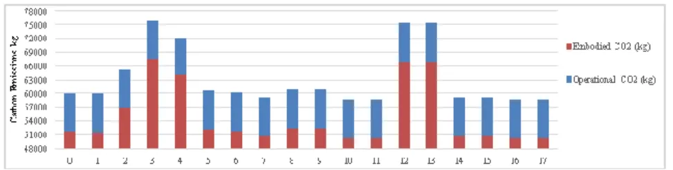
a.Embodied and Operational CO2 Emissions
Figure 8 indicates embodied and operational CO2 emissions released to atmosphere in different scenarios as a consequence of energy demands. Operational emissions are almost the same for all of them, which is around 8400 kg as well as floor options around 8100 kg. On the contrary, emissions due to embodied CO2 make the difference. AAC partition wall and aerated brick exterior wall options are better than others with 50280 kg release regardless with their thermal mass qualities. Floor with thicker screed has 67650 kg CO2 emission followed by reinforced concrete exterior wall in terms of highest embodied CO2 release. Consequently, it can be seen that investigations particularly about thermal mass quality are not sufficient in order to decide on construction materials for sustainable building. It is also noted that the differences in carbon emissions from one material to another are not influenced by insulation layer placement.
Figure 8.
Figure 7.
Energy consumption of scenarios for heating and cooling
Figure 8.
Embodied and operational carbon emissions of scenarios
Jour na l of A rc hite cture a nd Pl an ni ng
70
b.Lifecycle CO2 EmissionsLifecycle CO2 emissions are studied in accordance with a lifespan of 50 years for three main structure components with different scenarios. Reinforced concrete exterior wall with inner insulation, followed by its outer insulation scenario, reaches the peak point with around 490.000 kg CO2 emission, whereas terracotta floor has the least as represented in Figure 9. In addition, the minimum emission for inner partitions is seen by gypsum board releasing 472.000kg, while solid brick partition reaches the maximum. As a result, there are essential impacts of lifespans of both the materials and the building itself on CO2 emissions. Common usage of reinforced concrete is obvious in Turkey, but the sharp difference between other materials in terms of environmental effects cannot be neglected.
Figure 9.
CONCLUSION
The heating and cooling load reduction due to thermal mass are the results of a complex set of interactions between amount and physical properties of mass, location and amount of insulation in the exterior wall, inner partitions and floors that effect solar gain. However, not only energy efficiency, but also CO2 production should also be considered as the evaluation criteria for energy oriented studies in buildings. It is clear that one of the major parameters effecting operational CO2 emissions of environmental performance is the fuel type (Dombaycı, 2012). Beside to fuel type, selection of material is essential in the evaluation of lifecycle environmental impact of a building. In this context, this study examined how thermal mass changes building behaviour and CO2 emissions while the fuel type is kept the same. Furthermore, this investigation allowed determining the effects of material selection on heat absorption capabilities of different building components. A flat in thermally insulated low-rise apartment building, situated in hot humid climate, is used to analyse seventeen scenarios over the modifications of thermal mass characteristics through which insulation layer placement, material type, location and thickness are combined for floor, partitions and exterior walls. The result of this study reveals that:
Figure 9.
CO2 emissions according to
Jour na l of A rc hite cture a nd Pl an ni ng
71
1. Thermal mass has a noticeable effect on thermal behaviour and CO2 production considering outer walls, inner partitions and floors together.
2. Variations made within floor configurations show the most effective results in terms of lifespan CO2 emissions and annual energy consumption.
3. Thicker screed floor scenario is the best option in terms of energy efficiency, but it has high CO2 emission.
4. Embodied carbon emissions have more remarkable effect than operational carbon emissions.
5. Terracotta floor scenario, producing the optimal carbon emission according to lifespans of materials, is not the best for energy efficiency.
6. Insulation placement creates differences in energy efficiency outcomes, while it does not change CO2 related values.
For further studies, another fuel types or natural ventilation in order to compare inner temperature results and keeping mass layer thickness same while varying U values of construction components are essential points to have more developed results.
ACKNOWLEDGEMENTS
We would like to thank to Izmir Institute of Technology, Faculty of Architecture, Building Physics Laboratory for the support of diagnostic equipment and licensed software in this study.
REFERENCES
ASHRAE Guideline. (2002). Measurement of Energy and Demand Savings. American Society of Heating, Refrigerating and Air- Conditioning Engineers, Inc., Atlanta.
Byrne, S., and Ritschard, R. (1985). "A parametric analysis of thermal mass in residential buildings". Proceedings of the ASHRAE/DOE/BTECC Conference on Thermal Performance of the Exterior Envelopes of Buildings: 2-5.
CIBSE TM 36. (2005). Climate Change and the Indoor Environment of Buildings. Chartered Institution of Building Services Engineers.
Climate Consultant v.5.4.
http://climateconsultant.software.informer.com/5.4/ (date of
connection, 2013)
DesignBuilder v.4. www.designbuilder.co.uk (date of connection, 2013)
Dombaycı, A. (2013). "Investigation of the Effect of Thermal Insulation for a Model House in Cold Regions: A Case Study of
Jour na l of A rc hite cture a nd Pl an ni ng
72
Turkey". Environmental Progress & Sustainable Energy: 527-537.
Duzgun, B., and Komurgoz, G. (2014). "Turkey’s energy efficiency assessment: White Certificates Systems and their applicability in Turkey". Energy Policy: 465-474.
Fernandez, N. (2008). "The influence of construction materials on life-cycle energy use and carbon dioxide emissions of medium size commercial buildings". MSc. Victoria University of Wellington.
Gregory, C., Moghtaderi, B., Sugo, H. and Page, A. (2008). "Effect of thermal mass on the thermal performance of various Australian residential constructions systems". Energy and Buildings: 459-65.
M & V Guidelines. (2008).. Measurement and Verification for Federal Energy Projects, Version 3. U.S. DoE. Federal Energy Management Program.
IPMVP: International Performance Measurement and Verification Protocol-Concepts and Options for Determining Energy and Water Savings V.1. (2001). International Performance Measurement and Verification Committee. Turkish Statistical Institute (TUIK). (2013). Energy Statistics:
Annual Import.
Zeng, R., Wang, X., Di, H., Feng, J. and Yinping, Z. (2011). "New concepts and approach for developing energy efficient buildings: Ideal specific heat for building internal thermal mass". Energy and Buildings: 1081-1090.
CV (Resume)
Mümine Gerçek
She was born in 1989 in Bulgaria. She graduated from Middle East Technical University Department of Architecture in 2013. She started her master program in İzmir Institute of Technology Department of Architecture in 2013. She has been working in the same department since 2014 as a research assistant on energy efficient buildings.
Zeynep DURMUŞ ARSAN
She was born in 1971 in İzmir. She graduated from Dokuz Eylul University Department of Architecture in 1992. She had her master degree in METU Department of Architecture in 1997 and her PhD on “Sustainable Architecture in Turkey” in İzmir Institute of Technology in 2004. She has been working in İzmir Institute of Technology since 1997 on local sustainability and architecture, sustainable building design and building energy performance simulations as the instructor.