International Conference and Exhibition on Electronic, Computer and Automation Technologies (ICEECAT’14), May 9-11,2014
Konya, Turkey
Abstract – Lifts/elevators are mechanical equipment for
moving people or goods in a vertical direction via moveable cabins or platforms on guide rails. They provide quick, easy, comfortable, and safe transport between floors. In machine rooms of lifts, there are cards to guide the cabin by interpreting the received commands. For sending and receiving data between the machine room and the cabin, there are generally two 24x0.75 flexible cables varying according to the number of floors. In order to eliminate these cables, we designed a Serially Communicating Lift System. This system enables data exchange between the cabin and the lift control card. The system was tested in a real lift system for two months. The system measured up after rectifying the faults during the test. Then, it was repeatedly tested for 45 days. These tests affirmed the applicability of our Serially Communicating Lift System. Keywords: Serial Communication, Flexible cable, Machine room, Lift card.
I.INTRODUCTION
The system that is provoked by a machine room and enables the transportation of people or load in a vertical direction through a cabin or a cage moving on guide rails in a shaft/hoistway is called Mechanical Freight Lift.[11]
Thanks to technology, lifts have been at the disposal of humanity, making everyday life easier for people.[2]
Figure-1 presents the basic structure of lifts. Main elements of lifts are as follows:
Control Panel: This panel is the computer of lift.
Engine: It moves the lift cabin according to the information coming from the control panel.
Counter-weight: It means the weight bound to the other end of the rope to balance the cabin weight within the shaft. Flexible Cables: They are the cables enabling communication between the cabin and the control panel. Cab/Cabin: It is the lift part that carries the load.
Figure 1-Basic Structure of a Lift [2]
Flexible Cable Connection between the Cabin and the Mainboard;
Display Data Floor Buttons Floor Counters Automatic Door Data
Top and Bottom Power Breaker Overload Switch
Cabin Lamp [4, 6]
The data conveyed from the control panel to the cabin; Display Data: The data sent to the display segments to show on which floor the cabin is.
Automatic Door Data: The data coming from the control panel in order to open and close the automatic door in the cabin.
Cabin Lamp: The data coming from the control panel in order to switch on or off the cabin lamp.
Button Leds: The data sent to the cabin leds in order to ensure that, when someone pressed on a button, its light is on until the cabin reaches to the wanted floor.
The data conveyed from the cabin to the control panel; Floor Buttons: The data sent to the control panel when someone presses on a button inside the cabin.
Floor Counters: The data sent to the control panel when the cabin moves up or down.
Top and Bottom Power Breaker: The data sent to the control panel when the cabin reaches the bottom or the top point. Overload Switch: The data sent to the control panel if the cabin is overloaded.
II.MATERIALANDMETHOD
A. Serial Communication Technique
This technique is crucial for business organisations, automation systems, and factories with a number of machines and engines, in terms of minimising the complexity, reducing the cost, making the control easier, programming the system easily as desired, and removing the need for an additional data link when new devices are added to circuits.
Today, serial communication has a wide area of utilisation. Microprocessors and the devices such as modem, printer, floppy disc, hard disc, and optical drives communicate in a serial way. In addition to these, serial communication is used in cases that the number of lines are aimed to be reduced. In serial communication, data are conveyed unidirectionally or bidirectionally on a single channel. As the number of lines is reduced, its data signalling rate is low as well.
Serial communication involves two ways of data communication. One of them is synchronous and the other is asynchronous.
Synchronous communication: In syncronous data transmission, data and clock pulse are transferred together. This situation dispenses with the need for start and stop bits. Moreover, syncronous communication is faster than
1
Serially Communicating Lift System
A.GÖLCÜK1 and H.IŞIK21 Karamanoglu Mehmetbey University, Karaman/Turkey, [email protected] 2 Selcuk University, Konya/Turkey, [email protected]
asynchronous communication as the former is based on character blocks. However, it is more expensive and includes more complicated circuits. Syncronous communication means that a transmitter and a receiver operate simultaneously. This is why it needs clock pulses. It initiates the transmission in the following way: At first, the transmitter sends a particular character known by the both sides. This character indicates the initiation of communication. When the receiver reads this character, communication starts. Then the transmitter sends data. This transfer process goes on until the data block is completed or the syncronisation between the transmitter and the receiver is lost.
Asynchronous communication: Leading characteristics of asynchronous communication are as follows:
Transfers are based on characters.
Parameters of each data communication device must be equivalent.
Figure-2 demonstrates the basic form of asynchronous communication and asynchronous data block. An asynchronous character consists of a start bit, a parity bit, data bits, and stop bits.
Figure 2-Asynchronous data block
Start bit: It is used to signalise that a character has proceeded to be sent. It is always sent as the first bit of transfer.
Data bits: The groups that compose these bits are made up of all of the characters and the other keys on keyboard.
Parity bit: It is used to check whether characters are transferred to the other side properly or not. If the receiver detects that the received parity bit is not equal to the computed parity bit, it fails and do not accept the character at that moment.
Stop bit: It indicates that a character has finished. It provides idle or dead times between characters. After a stop bit is sent, new data can be sent at any time.
Baud: It is a unit of data communication speed expressed as bit per second. It is the rate of analogue signal change. Asynchronous serial data links use the data in the form of ASCII coded characters. Asynchronous communication requires 10 data bits in total to transmit 7 useful data bits. This is why asynchronous communication is inefficient to a certain extent. [1]
B. Structure of the System
A lift is basically made up of an engine, control panel, counter-weight, cabin, flexible cables, power cables etc. This study aims to show how a lift can use of serial communication by dispensing with the 24x0.75 flexible cables that are used in the electronic communication system of the lift and constantly move along with the cabin. Figure-4 shows the system we have developed. As it is understood from the diagram, two circuits have been designed, one of them is for the machine room, the other for the cabin. These
circuits include a microcontroller module, a data input module, a data output module, a power module, and serial communication modules. These circuits pave the way for removing the flexible cables in the lift system.
Figure 3- The lift system with serial communication link [2] Basic electronic materials in serial communication circuits;
PIC16F877A, IC (Integrated Circuit) CD4067, IC Uln2803, IC 74Ls273, IC UDN2981, IC Max485, Lm2576T-5 Step-Down Switching Regulator, PC817 Photocoupler etc. Pic16f877A Microcontroller IC;
It is a 16f series microcontroller with 33 input/output ports, six of these belong to PortA, eight to PortB, eight to PortC, eight to PortD, and three to PortE. It has three timers and one analog-digital converter. It is a programmable IC to which the software we developed for this system is uploaded. In short, it is the brain of the serially communicating lift system. The two circuits we have designed contain each of this IC. The data which this IC receives via the written software are transmitted from the cabin to the lift card module in the machine room through serial communication, and from the lift card to the cabin module through serial communication again. [5]
IC CD4067;
This is a 16-input and single-output multiplexer IC. Its purpose is to check 32 inputs through six Pic ports. Therefore, instead of using 32 pins, six pins are used from Pic. This IC was used in both cards two times for each. Control bits of each IC were checked by the 0.,1.,2. and 3. ports of Pic16f877 PortA. Output pins of CD4067 ICs were read from the 4. and 5. ports of PortaA as well. In this way, 32-input data were controlled via six Pic16F877 ports. IC ULN2803;
This IC consists of eight Darlington transistors. These transistors are composed of two NPN transistors. This IC was used for the displays inside the cabin. The cabin displays are seven-segment displays with common anodes. IC ULN2803 drives the segment ends (cathode ends) of the displays. In the meantime, this IC transmits the data coming from the buttons and the lift card to IC CD4067 inputs.
IC 74LS273;
This is an eight-input and eight-output data flip-flop IC. It can keep the eight outputs until the next clock pulse. Four ICs of this type were used in each circuit. It keeps the data coming from Pic to the lift card and the cabin until the next clock pulse.
IC UDN2981;
This is an eight-input and eight-output IC with a capacity of output voltage reaching up to 50V. Four ICs of this type were used in the lift card module, and three ICs of this type were used in the cabin module. Its intended purpose is to increase the 5V-output of 74LS273 to 24V and to convey it to the lift card and the cabin inputs.
Lm2576T-5 step-down switching regulator;
As the circuit components of the lift system operate on 24V, our circuits were supplied with 24V adaptors. The ICs of TTL and CMOS used in our circuits operate on a voltage of +5V. With a wiring diagram seen in Figure-22, a power circuit module was designed and +24V was lowered to +5V. This circuit converts the input voltages between 7-40V to a 5V output voltage.
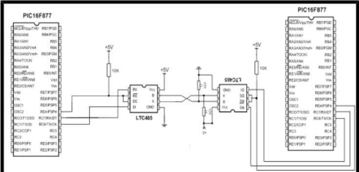
IC SN 75176 N;
One IC of this type was used in each module. Serial data communication between Pic16F877 microcontrollers takes place by way of this IC. This IC ensures a serial communication reaching up to 300m. Figure-4 presents the connection diagrams regarding the serial data communication of circuits.
Figure 4- Conncetion diagram of serial data communication between Pics
PC817 photocoupler;
The cabin lamp used in the lift system runs on 220V AC. Its automatic door runs on 190V DC. In order to eliminate the cables between the cabin and the machine room, our system involved a module with PC817 to take trigger from 220V AC and 190V DC voltages. Circuits were protected from high voltages and heavy currents thanks to this circuit. C. Serial Communication Software
Pic Basic Pro commands enabling serial communication are as follows:
Data sending command:
SEROUT2 VERIOUT,188,["S","U",BITLER1]
This command transmits data at 4800 baud rate. It transmits the letters “S” and “U” before sending BITLER1 data.
Data receiving command:
SERIN2 VERIIN,188,100,ATLA,[WAIT ("SU"),BITLER1]
This command reads the data sent at 4800 baud rate and transfers the data coming after the regularly sent letters “S” and “U” to BITLER1 variable.
Each circuit has four of these commands to send and receive data. As each command can convey 8-bit data, 32 bits of data are transmitted from the cabin to the machine room, and 32 bits of data from the machine room to the cabin.
III. APPLICATION
Microcontroller software in this Serially Communicating Lift System was written by using PicBasic Pro program. Printed circuits were prepared via Ares 7 Professional inside the Proteus 7 Professional program package. We used two-sided printing technique while plotting these printed circuits. In addition, before transferring the circuits into printed circuits, working principles of the used codes and ICs were tested on the simulation program of Isis 7 Professional.
We designed two serial communication circuits, one for the cabin and the other for the machine room. These circuits were tested on a lift prototype at first. After we got the desired results, the circuits were assembled to a real lift system together with lift technicians. At the first stage, malfunctions were detected and notes were taken. Following the necessary changes in software and hardware, the system was tested again. After the tests bore fruit, it was observed that the serial communication technique can be used in the lift system.
IV. CONCLUSION
This system eliminates the two 24x0.75 flexible cables used in the electronic communication system of lifts, moving with their cabin. Moreover, it obviates the possible failures due to cable ruptures and minimises the time spent for repairing. There are two LEDs on each circuit to show whether serial communication is taking place or not. If the red LED is on, it means that serial communication is failing; if the blue one is on, it means that serial communication is running. Whether there is a systemic failure or not can be detected easily in this way.
Table 1-Flexible Cable Prices
SIZES Nominal
Section Diameter (mm) Height (mm) Weight (gr/m)
Price (m) Price per unit
(m) Vat included 12x0.75 33.8 4.2 284 3 TL 3,54 TL 16x0.75 44.4 4.2 366 4,7TL 5,55 TL 20x0.75 55 4.2 463 4,96 TL 5,85 TL 24x0.75 75.6 4.4 740 5,28 TL 6,23 TL [7, 10] 3
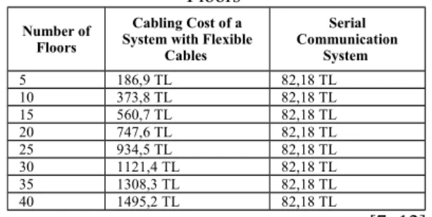
Table 2- Cost Comparison in Respect to the Number of Floors
Number of Floors
Cabling Cost of a System with Flexible
Cables Serial Communication System 5 186,9 TL 82,18 TL 10 373,8 TL 82,18 TL 15 560,7 TL 82,18 TL 20 747,6 TL 82,18 TL 25 934,5 TL 82,18 TL 30 1121,4 TL 82,18 TL 35 1308,3 TL 82,18 TL 40 1495,2 TL 82,18 TL [7, 12] Table-1 shows the prices of flexible cable used in lift systems. Tablo-2 presents a cost comparison of a flexible cable system and a serial communication system. While calculating the cost of flexible cable, inter-floor distance was considered as 3m. Two flexible cables of 24x0.75 sections are used. The cost of flexible cable for a five-storey building was found as 5*6,23Tl*3m*2=186,9TL. After all, it is seen that more floors there are, more economical the serial communication system is in comparison to the flexible cable system.
EXCERPT
This study was excerpted from the PhD dissertation under the title of “Design and Actualisation of the RF-controlled Lift System” written for Selçuk University Institute of Science in 2010.
REFERENCES
[1] Canbolat, A., 2009. Mikrodenetleyici İle Tek Hat Seri İletişim Hazırlayan Akif Canbolat, http://320volt.com/mikrodenetleyici-ile-tek-hat-seri-iletisim-pic16f84 [Date Accessed: 4 Kasım 2009] [2] Gölcük A, 2010. Design And Actualisation Of The RF-Controlled
Lift System, PhD Thesis, Graduate School of Natural and Applied Sciences, Selçuk University, 75 P. Konya
[3] Görgülü, Y., E., 2007. RTX51 İle Asansör Otomasyonu, Yüksek Lisans Tezi, Süleyman Demirel Üniversitesi Fen Bilimleri Enstitüsü, 100 S., Isparta
[4] Kan, İ., G., 1997. Asansör Tekniği : Elektrikli / İbrahim G. Kan. 326 s. ; 28 cm. Yayın yeri; İstanbul, Birsen Yayınevi, [t.y.] [5] Megep, 2007. Bilişim Teknolojileri/Mikrodenetleyiciler 1,
ANKARA,http://megep.meb.gov.tr/mte_program_modul/modul_p df/523EO0191.pdf [Date Accessed: 4 Eylül 2009]
[6] Mikrolift Mühendislik, 2007. ML60X Programlama (Ver:2.78), Konya, 03, ARALIK,2007, http://www.mikrolift.com.tr/tr/pdf/ l60xskullanimklavuzu.pdf, [Date Accessed: 05 Nisan 2010] [7] Nergis Kablo, 2010. H05VVH6-F Kablo, Nergiz Kablo San. ve
Tic.Ltd.Şti.,İstanbul,
http://www.nergizkablo.com.tr/urun_227iec71f.htm [Date Accessed: 05 Mayıs 2010]
[8] Özden, S., 2007. Bir Elektrikli Asansör Sisteminin Bulanık Mantık Tekniği İle Denetimi, Yüksek Lisans Tezi, Gazi Üniversitesi Fen Bilimleri Enstitüsü, 116 S., Ankara
[9] Sarıbaş, Ü., 2006. Akıllı Bir Asansör Sisteminin Benzetimi, Yüksek Lisans Tezi, Gazi Üniversitesi Fen Bilimleri Enstitüsü, 129 S., Ankara
[10] Sword Lift, 2010. Sword Lift Asansör Market,
http://www.onlineasansormalzemesi.com/24X075-MM-FLEXIBLE-KABLO-pid-106.html [Date Accessed: 10 Nisan 2010]
[11] Texier, G., 1972. Asansör Tesisleri :Temel Bilgiler, Kosrüksiyon, Proje ve Hesap Esasları/Georges Texier;Çeviren Uğur Köktürk. 166 s. ; 26 cm. İstanbul:İnkılap ve Aka Basım Evi
[12] Tüm Elektronik, 2010. İstanbul, http://www.bluemavi.com/ [Date Accessed: 10 Mayıs 2010]
![Figure 1-Basic Structure of a Lift [2]](https://thumb-eu.123doks.com/thumbv2/9libnet/4546723.82473/1.918.123.396.826.1069/figure-basic-structure-of-a-lift.webp)
![Figure 3- The lift system with serial communication link [2] Basic electronic materials in serial communication circuits;](https://thumb-eu.123doks.com/thumbv2/9libnet/4546723.82473/2.918.126.399.461.591/figure-serial-communication-basic-electronic-materials-communication-circuits.webp)