HARMONIC EFFECTS ON ELECTROMECHANICAL
OVERCURRENT RELAYS
HARMON KLER N ELEKTROMEKAN K A IRI AKIM RÖLELER ÜZER NDEK ETK LER
K. Burak DALCI, Recep YUMURTACI, Altu BOZKURT
Yıldız Technical University, Electrical Engineering DepartmentABSTRACT: The electromechanical overcurrent protection relays are designed to operate with sinusoidal current. The operation of protective relay with harmonic currents is not reliable. The literature on harmonics and relays covers mostly the theoretical studies. In this paper, the harmonic effects on operation of electromechanical inverse time overcurrent relay (ITOCR) were examined. Not common in existing studies, the behaviour of ITOCR was analysed with laboratory experiments for distorted waveforms. A type of induction disc relay was used as an electromechanical ITOCR in the experiments. The non-sinusoidal load currents that consist of different harmonic spectra were applied to ITOCR and these nonlinear-load currents were processed by a data acquisition card and a harmonic analysis programme in the computer environment. According to the experiment results, the pick up current and the operating time of the ITOCR increase proportionally to the total harmonic distortion (THD) value of the non-sinusoidal current. It is concluded that, this type of relay cannot protect the system reliably due to the harmonic components of current.
Keywords: Electromechanical, relay, harmonic, overcurrent.
ÖZET: Elektromekanik a ırı akım koruma röleleri sinüsoidal akım altında çalı mak üzere
tasarlanmı tır. Bu rölelerin harmonikli akımda çalı maları güvenilir de ildir. Literatürde harmonikler ve rölelerle ilgili pek çok teorik çalı ma bulunmaktadır. Bu makalede, harmoniklerin elektromekanik ters zamanlı a ırı akım rölesinin (TZAAR) çalı masına etkileri incelenmi ve TZAAR’nin bozulmu dalga ekilleri için davranı ı deneysel çalı ma ile analiz edilmi tir. Deneyde, elektromekanik TZAAR olarak, indüksiyon disk yapısında bir röle kullanılmı tır. De i ik harmonik spektrumlara sahip, sinüsoidal olmayan yük akımları TZAAR’a uygulanmı ve bu yük akımları data toplama kartı ve harmonik analiz programı ile bilgisayar ortamında i lenmi tir. Deney sonuçları gözönüne alındı ında, TZAAR’ın çalı ma akımı ve çalı ma zamanının, sinüsoidal olmayan akımın toplam harmonik distorsiyonu (THD) ile orantılı olarak arttı ı görülmü tür. Bu yapıda olan bir rolenin, akımın harmonik içermesi durumunda sistemi güvenli bir ekilde koruyamayaca ı sonucu elde edilmi tir.
Anahtar kelimeler: Elektromekanik, röle, harmonik, a ırı akım.
1. Introduction
In recent years, the advancements in power electronic components have led to the increased usage of non-sinusoidal currents and voltages in power systems. The problem of nonlinear loads was already existing and was especially experienced with ac and dc variable speed drivers, switch mode power supplies, power semiconductor controllers and other nonlinear loads. These devices produce harmonics in voltage and current waveforms during operation.
Harmonic currents can cause some problems in overcurrent protection relays that provide complete protection and reliability for the power systems. Most of the relay manufacturers design their relays for pure sinusoidal currents and voltages. The well-known characteristics of relays are not valid under distorted waveforms. Each harmonic frequency component could produce an independent and cumulative effect,
causing the pick up value to change depending on the magnitudes of harmonic components. Therefore, the relays cannot protect the lines or transformers reliably when harmonics are involved.
In 1988, Fuller, Fuchs and Roesler studied the effect of the harmonics on various types of protective relays and this research was supported by U.S. Department of Energy. The paper shows that static (solid-state) and electromechanical overcurrent relays were affected by the presence of harmonic currents when pick up values were concerned (Fuller, et al., 1998: 549-557).
In 1993, Elmore et al. published a study that attempted to show theoretically and by laboratory tests the influence of harmonics on protective relays. The type of induction disc relay was tested by using single frequency inputs that were multiples of the fundamental frequency and some realistic combinations of fundamental and other harmonics. As frequency increases from the fundamental to the odd harmonics up to the 9th, the torque produced on the disc by the electromagnet decreases for a given rms current, hence producing a higher minimum pick up. The inadequate torque produced, caused the disc to move for frequencies higher than the 5th order, with current as high as 10 multiples of pick up. As the relay becomes less efficient for the increased frequencies, operating times get longer and the time curves shift up (Elmore, et al., 1993: 404-411).
In 1994, Rob et al. presented a research that discusses a simulation method to study harmonics using a computer based three phase harmonic source. This simulation method was used to test the performance of ground directional overcurrent relay, so that the response of the relay was provided for distorted environment. Experimental results prove that the operation of this relay is not reliable in case the total harmonic distortion (THD) is 40% or greater in current distortion (Rob, et al., 1994: 125-135). Today, digital type protection relays are gradually taking the place of electromechanical protection relays in the world, but the electromechanical ones are still used in Turkey because of their robust structure. The purpose of this paper is to determine the behaviour of the electromechanical ITOCR for nonlinear-load currents that consist of different harmonic spectra. In this experimental study, non-sinusoidal load currents were applied to the ITOCR and these currents were processed by a data acquisition card and harmonic analysis programme in the computer environment. With this approach, the current-time curves of the ITOCR are determined for distorted waveforms. According to the experimental results, the pick up current and the operating time of the ITOCR increase with respect to the total harmonic distortion (THD) value of the non-sinusoidal current. Therefore, this type of relay cannot protect the system reliably due to the harmonic components of current.
2. Behaviour of the Electromechanical ITOCR
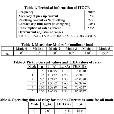
ITOCR is used for overcurrent and short circuit protection of lines in power systems. The main element of an electromechanical ITOCR is the induction disc unit. This type of relay consists, in one implementation, of a three-pole electromagnet as shown in Figure1 (Applied protective relaying, 1976: 3-5). All of the operating energy for the relay is applied to the center pole coil. One outer pole is equipped with a lag coil. The remaining pole has no coil. Current I that is in the main coil, produces flux, , which passes through the air gap to the disc, finally it arrives to the keeper. The flux, ,
returns as L through the left-hand leg and as R through the right-hand leg, where
= L + R. A short-circuited lagging coil on the left leg causes L to lag both R
and . With fundamental pickup current applied, torque of sufficient magnitude is proposed to overcome the spring restraint and to cause the disc to just begin to move. This torque results from interaction between disc currents produced by each pole and the other two pole fluxes. All of these torques are in the same direction (Applied protective relaying, 1976: 3-4), (Horowitz, et al., 1992: 28-31).
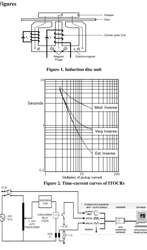
The standard current-time characteristic curve of ITOCR is shown in Figure 2. In this figure, the extremely inverse relay saturates at four multiples of pickup, very inverse at two multiples (half the previous), and the moderately inverse at pickup (again, half the previous value) (IEEE standard inverse-time, 1996: 10).
Increasing the frequency of the input current results in little change in the current that is produced in the lag coil circuit. However, the flux in this pole will decrease in inverse proportion to the frequency increase, maintaining the behaviour of the electromagnet as the equivalent of a current transformer. Similarly, the flux in the other outer pole decreases because of the lowered magnetomotive force across it. Since the flux in the center pole is the sum of the two outer pole fluxes, it is also reduced. By decreasing the magnetising current for frequency increment and constant lag coil circuit current, the net effect is for the center pole and the unlagged pole fluxes draw closer in phase. This slows down the disc rotation, causes the pick up to increase, and ultimately causes the efficiency of the electromagnet to deteriorate to the point of non-operation. Harmonics combined with the fundamental have serious effects on ITOCR pick up current value and operation time.
3. Components of the Test System
A test system configuration consists of data acquisition hardware, software and the protective relay as illustrated in Figure 3.
3.1. Data Acquisition Hardware
Current of the nonlinear load was isolated by a current transformer (CT) that has a transformation rate 5A to 5A. The current data was converted to the voltage data by a 1 resistance (1% tolerance, 25W) that was connected to the current transformer secondary winding. The converted signal data was acquired as 1000 samples at a 20 kHz sampling rate from a single ended input channel with 12 bits resolution by PCI-1200 National Instruments data acquisition card that was connected to the PCI slot of a personal computer. The data acquisitiondevice is low-cost, multifunction I/O device with up to 100 kS/s, 12-bit performance on 8 single-ended or 4 differential analogue inputs. The device features digital triggering capability; three 16-bit, 8 MHz counter/timers; two 12-bit analogue outputs; and 24 digital I/O lines (Labview user manual, 1998: 250-251).
3.2. Data Acquisition Software
The proposed programme takes signals in and performs a full harmonic analysis, including measuring the fundamental frequency tone, other harmonics, and returning the fundamental frequency, all harmonic amplitude levels, and the total harmonic distortion (THD) by using LabVIEW graphical programming language. THD is defined as the ratio of the rms sum of the harmonics to the amplitude of the fundamental component.
The programme converts the sampled signal with a 20 kHz sampling frequency to frequency domain using a Fast Fourier Transform (FFT) algorithm. The current spectrum is generated by an FFT algorithm with 4096 point and includes only the magnitude information for each harmonic component. All harmonics were measured at integer multiples of this fundamental frequency (50 Hz). To decrease the signal noise in current spectrum, FFT algorithm was calculated ten times and the average value of this calculation is evaluated when determining the harmonic behaviour of ITOCR.
3.3. Relay
ITOCR is used to protect electrical installations in selective protection. Operating time of this relay is inversely proportional to the current. The electromechanical ITOCR that was tested in the experiment, has been protecting most of the installations in Turkey because of their robust structure. Technical information of the relay is given in Table 1 and the time-current characteristic is illustrated in Figure 4.
4. Experimental Study
The test circuit for ITOCR is shown in Figure 3. Resistive load which was controlled by a dimmer circuit was used as a nonlinear load. The waveform of the nonlinear-load current is shown in Figure 5 after dimming operation for any firing angle. Root mean square (rms) value of current (Irms) and total harmonic distortion value of current
(THDi) of such a nonlinear-load current were defined in Eq.1 (Wakileh, 2001: 16-17)
and Eq.2 (Arrillaga, et al., 1985: 201) respectively, + = =2 2 2 1 n n rms I I I (1) 1 2 2
I
I
THD
i=
n= n (2)where n is the harmonic order, I1 is the fundamental component and In is the nth
harmonic component of the nonlinear-load current.
In the test circuit, the rms value and the total harmonic distortion of the nonlinear-load current (THDi) are adjusted by changing the firing angle of triac (α). As a result of
changing the firing angle, the nonlinear-load voltage changes.
In the experiment, the effects of non-sinusoidal currents on the dynamic behaviour of electromechanical ITOCR were analysed. The firing angle of the triac (α) was set to six different values to obtain different harmonic spectra in load current. All of the measurements were realised for these six different experiment modes as shown in Table 2. As α was changed, the harmonic spectrum of the nonlinear-load current changed; therefore harmonic spectrum of nonlinear-load current was different for each mode. In each mode, α was set to a constant value and the rms value of nonlinear-load current was changed by adjusting the auto transformer voltage. The true rms current value (Irms), total harmonic distortion value (THDi), the rms value of fundamental
current (I1) and operating time of the relay were measured for each mode. For all
currents and this setting was not changed during the experiment. According to the experimental results, the pick up current of ITOCR was affected by the presence of harmonic currents and the pick up value was increased by non-sinusoidal currents. This increment depends on the total harmonic distortion value of the nonlinear-load current. The waveform of the network voltage was expected to be purely sinusoidal however it was distorted and the total harmonic distortion value of the network voltage (THDv) varied between 5% and 7% during the experiment. THDv is defined in Eq.3
(Arrillaga, et al., 1985: 201), 1 2 2
V
V
THD
n n v=
= (3)where n is the harmonic order, V1 is the fundamental component and Vn is the nth
harmonic component of the voltage.
With respect to the experimental results, the pick up current and THD value of the non-sinusoidal current are given in Table 3. The pick up current increased as long as THD value of current was increased. When THDi was above 86%, the relay which
was set to 1 ampere for sinusoidal current, operated at 1.9 ampere. This shows that the relay cannot perform a proper protection function and causes damage or heating-up depending on the rms value of the current and the process time in power system components such as transmission lines, motors and transformers.
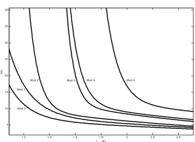
The variation of relay operating time versus the rms value of relay current is shown in Figure 6. The relay has different operating time values for the same relay current values in different modes as shown in Table 4. Since the relay induction disc rotates rather slowly because of nonlinear-load current harmonic components, relay operating time will increase as long as THD value of current increases. Power system components that are protected by this relay will be damaged because of the increase in the operating time.
5. Conclusion
In this paper, it is shown with experimental results that ITOCR, designed to work with sinusoidal currents, cannot operate effectively with non-sinusoidal currents that consist of several harmonic components. Relay pick up current will increase as long as THD value of the current increases as shown in Table 3. As given in Table 4, the harmonic spectra of current changes in spite of rms value of relay, non-sinusoidal current remains constant and relay operating time increases as long as THD value of current increases. Distortion increment leads to increase in the operating time of the relay as shown in Table 4. Thus, power system components may be exposed to heat and finally may be damaged. Furthermore, the coordination of these relays cannot be realised perfectly for non-sinusoidal currents.
References
Applied protective relaying, (1976). Newark, Westinghouse Electric Corporation
Relay-Instrument Division.
ARRILLAGA, J., BRADLEY, D.A. & BODGER, P.S. (1985). Power system
ELMORE, W.A., KRAMER, C.A. & ZOCHOLL, S.E. (1993). Effect of waveform distortion on protective relays. IEEE Transactions on Industry applications, Vol. 29, No. 2, March/April, pp. 404-411.
FULLER, J.F., FUCHS, E.F. & ROESLER, D.J. (1998) Influence of harmonics on power distribution system protection. IEEE Transactions on Power Delivery, Vol 3, No. 2, April, pp. 549-557.
HOROWITZ, S.H., PHADKE, A.G. (1992). Power system relaying. John Wiley & Sons Inc.
IEEE standard inverse-time characteristic equations for overcurrent relays, 1996.
Power System Relaying Committee of the IEEE PES, IEEE Std. C37112.
LabVIEW user manuel. (1998). Texas, National Instruments.
ROB, R.A., JEWELL, W.T. & TESHOME A. (1994). Computer based harmonic simulation and testing for directional-overcurrent relays. Electric Power System
Research, Vol 31, pp. 125-135.
WAKILEH, G.J. (2001). Power systems harmonics – fundamentals, analysis and filter
design. Berlin, Springer-Verlag.
Tables
Table 1. Technical information of ITOCR
Frequency 50Hz
Accuracy of pick up current ±5%
Resetting current as % of setting 92% Contact stop time (after de-energizing) 0.08s
Consumption at rated current 5VA
Overcurrent adjustment ranges
1.00A – 1.25A – 1.50A – 2.00A – 2.50A – 3.00A – 4.00A Table 2. Measuring Modes for nonlinear load
Mode-0 Mode-1 Mode-2 Mode-3 Mode-4 Mode-5
α αα
α 00 300 600 900 1200 1500
Table 3. Pickup current values and THDi values of relay
Mode αααα I1 (A) Irms (A) THDi(%)
0 0o 1.0975 1.10 6.0010 1 30o 1.1422 1.20 35.3101 2 60o 1.2177 1.30 46.0880 3 90o 1.3352 1.60 68.9976 4 120o 1.3888 1.68 70.6527 5 150o 1.4583 1.90 85.8677
Table 4. Operating times of relay for modes (Current is same for all modes) Mode Irms (A) THDi (%) t (s) 0 2.00 6.43 4.634 1 2.00 27.45 5.268 2 2.00 35.12 5.984 3 2.00 59.50 8.682 4 2.00 65.23 9.582 5 2.00 85.20 14.964
Figures
Magnet Plugs φ L φ φR S Ι Ι Keeper DiscCenter pole Coil
Electromagnet
Figure 1. Induction disc unit
Figure 2. Time-current curves of ITOCRs
2 3 4 5 6 7 8 9 10 2 3 4 5 6 7 8 9 10 11
Multiples of Pickup Current
t(
s)
Figure 4. Time-current characteristic of ITOCR for sinusoidal current
α π α +π 2π ωt ) (t i m I
Figure 5. Nonlinear-load current
1.2 1.4 1.6 1.8 2 2.2 2.4 5 10 15 20 25 30 35 40 Irms (A) t( s) Mod 0 Mod 1
Mod 2 M od 3 Mod 4 Mod 5