https://doi.org/10.1007/s11554-018-0830-8
ORIGINAL RESEARCH PAPER
Exploiting architectural features of a computer vision platform
towards reducing memory stalls
Naveed Ul Mustafa1 · Martin J. O’Riordan2 · Stephen Rogers2 · Ozcan Ozturk1
Received: 24 September 2017 / Accepted: 1 October 2018 / Published online: 9 October 2018 © Springer-Verlag GmbH Germany, part of Springer Nature 2018
Abstract
Computer vision applications are becoming more and more popular in embedded systems such as drones, robots, tablets, and mobile devices. These applications are both compute and memory intensive, with memory bound stalls (MBS) making a significant part of their execution time. For maximum reduction in memory stalls, compilers need to consider architectural details of a platform and utilize its hardware components efficiently. In this paper, we propose a compiler optimization for a vision-processing system through classification of memory references to reduce MBS. As the proposed optimization is based on the architectural features of a specific platform, i.e., Myriad 2, it can only be applied to other platforms having similar architectural features. The optimization consists of two steps: affinity analysis and affinity-aware instruction scheduling. We suggest two different approaches for affinity analysis, i.e., source code annotation and automated analysis. We use LLVM compiler infrastructure for implementation of the proposed optimization. Application of annotation-based approach on a memory-intensive program shows a reduction in stall cycles by 67.44%, leading to 25.61% improvement in execution time. We use 11 different image-processing benchmarks for evaluation of automated analysis approach. Experimental results show that classification of memory references reduces stall cycles, on average, by 69.83%. As all benchmarks are both compute and memory intensive, we achieve improvement in execution time by up to 30%, with a modest average of 5.79%.
Keywords Computer vision · Compiler optimization · Execution time · Memory bound stalls
1 Introduction
Computer vision (CV) is a rapidly growing field, mostly devoted to capturing, analysis, modification, and understand-ing of images [1, 2]. With the arrival of high-resolution cam-eras in mobile devices, CV applications are becoming more popular [1]. Embedded systems such as wearable devices, drones, robots, and tablets are supposed to support CV
applications [3]. Domains that employ CV include surveil-lance [4, 5], gesture recognition [6], face tracking [7, 8], medical imaging [9, 10], automotive safety [11, 12], and food industry [13–15], among others.
Computer vision applications are computationally expen-sive and mostly required to execute in real time [1]. How-ever, embedded platforms are limited on the power budget. There are two architectural solutions to reduce the power consumption and running the CV algorithms faster on embedded systems. One popular approach is to use a multi-core platform. In general, two smaller multi-cores collectively occupying the same area and consuming the same energy as compared to a single large core can provide 70–80% higher performance [16]. The other possible approach is using the dedicated optimized cores to implement the commonly used algorithms. This can be achieved using domain-specific hardware accelerators [1]. Besides employing architectural solutions, it is critical for a compiler to reduce the execution time of applications by taking into account the architectural features of the hardware platform [17].
* Naveed Ul Mustafa [email protected] Martin J. O’Riordan [email protected] Stephen Rogers [email protected] Ozcan Ozturk [email protected]
1 Department of Computer Engineering, Bilkent University,
Ankara, Turkey
There have been various efforts to design vision-process-ing systems targetvision-process-ing CV applications such as [2, 17–19], among others. One such effort is Myriad 2 platform from Movidius [20]. It is a low-power multi-processor system on chip (MPSoC) that uses an array of very long instruction word (VLIW) processors with vector and single instruction multiple data (SIMD) execution capabilities [21]. Each pro-cessor supports two load and store units (LSUs) to overlap latency of memory operations. Since CV applications are heavy in both computation and memory requirements [22], the platform features a high bandwidth memory subsystem. However, being unaware of the memory organization, the compiler of Myriad 2 platform schedules memory accesses inefficiently. This results in unnecessary memory stalls and hence higher execution time for applications.
In this paper, we motivate the need to reduce memory bound stalls (MBS) in CV applications and identify the problem faced by the compiler of Myriad 2 platform in reducing such stalls. Our main contributions in this paper can be summarized as follows.
1. We propose an optimization through classification of memory references aiming to reduce MBS. The optimi-zation consists of two steps: affinity analysis and affin-ity-aware instruction scheduling (AAIS). While affinity analysis predicts the physical memory location for each memory object in the application’s source code, AAIS generates a stall-saving instruction schedule based on the results of affinity analysis step. A compiler equipped with the proposed optimization is named an affinity-aware compiler (AAC).
2. We propose two different affinity analysis approaches along with their motivation, namely, source code annota-tion and automated analysis.
The proposed optimization is based on efficiently utilizing the hardware components of Myriad 2 and, therefore, not applicable as it is to other platforms. However, it is expected to be relatively easy to adapt the optimization for other CV platforms with similar architectural features.
We implement the proposed optimization on LLVM com-piler infrastructure [23] and evaluate it by running bench-marks on the Myriad 2 board using the base compiler (BC) and the AAC. We apply annotation-based analysis approach only on a simple memory-intensive test program. It shows the reduction in stall cycles by 67.44% resulting in 25.61% improvement in the execution time. We evaluate the auto-mated analysis approach by running 11 different compute and memory-intensive image-processing benchmarks on a Myriad 2 board using the AAC. Results show that AAC reduces stall cycles by 69.83% with a modest improvement in the execution time by 5.79%, on average, as compared to the BC.
The rest of this paper is organized as follows. Sec-tion 2 describes the related work, while Sect. 3 motivates the reduction of MBS for CV applications. Section 4 pro-vides the necessary details of a Myriad 2 platform needed to understand this work. Section 5 formulates the problem faced by the compiler in reducing MBS and proposes the solution. Section 6 provides the implementation details. Methodology for evaluation of proposed optimization is described in Sect. 7, while Sect. 8 shows evaluation results. Section 9 concludes this paper.
2 Related work
Memory bound stalls cause underutilization of the compute logic due to memory latency and hence become a major hur-dle in improving the execution time of an application [24]. Various approaches have been proposed to reduce memory stalls, such as data mapping in multi-bank environment, using non-uniform memory access (NUMA)-based design and architectural improvements in the memory and compute fabric.
Platforms with multi-bank memory system mitigate the problem by mapping simultaneously requested data on dif-ferent memory banks. Researchers have presented proposals to implement data mapping as a back-end compiler optimi-zation [25, 26] as well as by analyzing memory access pat-tern at higher levels [27–29] for single-processor systems. Other works, such as [30, 31], propose approaches for map-ping data of different applications to multiple memory banks in a multi-core environment.
NUMA is commonly used in modern multi-processor systems to avoid the bottleneck of shared memory accesses [32]. It provides asymmetric memory bandwidth and latency characteristics [33]. In other words, cost of accessing data located in remote memory modules is higher than access-ing data blocks in local memory modules. Memory affinity is a way to reduce this cost by placing the data in memory modules closer to the processor executing the computation thread [34] and guarantees to improve memory bandwidth and latency [35].
Many researchers have contributed in the context of mem-ory affinity to reduce memmem-ory access cost on NUMA plat-forms. For example, an NUMA API for Linux was proposed in [36] which allows programmers to make memory alloca-tions from a specific node or memory module, in addition to binding threads to specific CPUs. Different algorithms have been proposed to spread application data across different memories of an NUMA platform, such as round-robin, first touch affinity and next-touch affinity [32, 37]. An extension to Linux kernel to add support for the affinity-on-next-touch algorithm is reported in [38].
In this work, we exploit the availability of dual load-store Units to processors of a vision-processing system and its NUMA architecture, where memory is divided into multiple slices, each one having an affinity to one of the processors. Unlike the traditional memory affinity approach focusing on the reduction of latency by placing data closer to the com-puting processor [32, 33, 37, 39], the purpose of our affinity analysis is to reduce the memory bound stalls by taking into account memory organization and hence efficiently schedul-ing memory accesses.
Another approach to reducing memory stalls, more related to our work, is optimization of the memory sub-system of the execution platform and related architectural components of the compute fabric. Like Myriad 2 platform, Snapdragon 800 [40], MaPU [17], and TI AcceleratorPac [18] use VLIW processors as main execution units [19] combined with RISC cores and other dedicated components. Unlike these systems using unified memory, Myriad 2 uses NUMA architecture enabling multiple cores to access their local memory slices simultaneously and hence make a con-tribution in reducing memory stalls.
Hexagon DSP on Snapdragon 800 is a VLIW featuring two data units. Each data unit is capable of executing a load, a store or an ALU instruction but unable to pack two mem-ory accesses with one or more ALU instructions in a single cycle. On the other hand, VLIW processors of Myriad 2 are capable of packing two memory accesses with up to two ALU instructions in a single cycle.
MaPU platform contains ten processing cores with uni-fied memory scheme. A core can make up to three memory accesses simultaneously but into different physical memo-ries. Furthermore, a physical memory cannot be accessed by different cores simultaneously. As compared to MaPU, Myriad 2 supports simultaneous accesses to memory at two levels. First, multiple cores can access their local memory slices simultaneously due to NUMA architecture. Second, each core can make up to two simultaneous accesses into its local slice.
As noted by designers of MapU [17], compilers are a major source of the lower performance of execution plat-forms as they use a simplified model of processor architec-ture and do not consider detailed architectural feaarchitec-tures of the
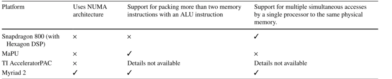
platform. Since our proposed compiler optimization is based on comparatively better architectural features of Myriad 2 platform (such as dual load-store units per processor and a high bandwidth memory subsystem), as shown in Table 1, it is not only different than Hexagon DSP and MaPU, but has a potential of achieving higher performance.
3 Motivation
The execution time of an application can be divided into two broad categories: commit cycles and stall cycles. A clock cycle is categorized as a commit cycle if at least one instruc-tion is retired during the cycle; otherwise, it is categorized as a stall cycle. Various reasons such as unavailability of functional units, bad branch prediction, or data dependencies result in stall cycles. The unavailability of data required for instruction execution incurs extra clock cycles in the form of a cache miss penalty. Such cycles are termed memory bound stalls (MBS).
We characterize a set of CV benchmarks to understand the distribution of execution time across different categories. The set consists of benchmarks performing basic image-pro-cessing operations such as image addition and subtraction [41], box filtering [42], convolution [43], sum of absolute difference [44], white balancing operation [45], histogram generation, and similarity measurement between pixels of two input images [46]. “Appendix” provides the critical part of the source code for benchmarks. We use Intel’s VTune performance analyzer [47] to breakdown the execution time of benchmarks into commit cycles (CC), bad speculation stalls (BSS), MBS, core bound stalls (CBS), and front-end bound stalls (FEBS).
As shown in Fig. 1, on average, MBS make almost 33% of the total execution time. It suggests the criticality of MBS in reducing the execution time of an application. Therefore, a platform running CV applications should have an efficient memory architecture supporting the data transactions with high bandwidth and low latency. In addition to that the soft-ware infrastructure, such as compiler and assembler, should
Table 1 Comparison of architectural features of different CV platforms
Platform Uses NUMA
architecture Support for packing more than two memory instructions with an ALU instruction Support for multiple simultaneous accesses by a single processor to the same physical memory.
Snapdragon 800 (with
Hexagon DSP) × ×
✓
MaPU × ✓ ×
TI AcceleratorPAC × Details not available Details not available
take advantage of architectural features offered by the plat-form to reduce MBS.
4 Myriad 2 architecture
Figure 2, based on [48, 49], shows the architectural layout of a Myriad 2 Platform developed by Movidius Ltd [20]. It is an MPSoC containing multiple heterogeneous processors, hardware accelerators, memories, and external interfaces. Target application domain for the Myriad 2 platform is video filtering and image recognition in embedded systems [49].
Myriad 2 contains 12 streaming hybrid architecture vec-tor engine (SHAVE) and two reduced instruction set com-puting (RISC) processors. SHAVE processors are the real workhorse of Myriad 2 and are designed to crunch the com-plex imaging and vision algorithms [48]. The platform offers a 2 MB connection matrix (CMX) memory along with a number of programmable hardware accelerators for vision processing. Accelerators are connected to the CMX memory via a crossbar [3].
SHAVE is a VLIW processor containing a set of func-tional units which are fed with operands from three differ-ent register files [21]. The processor contains optimized functional units such as a branch and repeat unit (BRU), a compare and move unit (CMU), arithmetic units, and
Fig. 1 Benchmarks: P1 = subtraction of two images, P2 = addition of four images, P3 = addition of two images, P4 = addition of two images based on a mask input, P5 = box filtering using 5 × 5 mask, P6 = addition of two scaled images, P7 = convolution using 3 × 3
mask, P8 = sum of absolute difference using a 5 × 5 window, P9 = white balancing operation, P10 = histogram generation, and P11 = similarity measurement between pixels of two images
two load-store units (LSUs). Each SHAVE processor can execute two load-store instructions simultaneously.
4.1 CMX memory
As shown in Fig. 3a, the 2 MB CMX memory is divided into 16 different slices, each with a size of 128 KB. A slice can hold both instructions and the data for a program running on a processor. Each of the first twelve slices (i.e., slice 0–slice 11) has an affinity to 1 of 12 SHAVE processors. Since Myriad 2 is a non-uniform memory access (NUMA) platform, it is more efficient in terms of latency and energy consumption for a processor to access its local slice (i.e., slice 0 for SHAVE 0). However, processors can also access any other slice in the CMX memory but with a higher latency. Therefore, placement of data in the local slice of a processor is recommended.
A slice is further divided into four regions, named
R0, R1, R2, and R3 in Fig. 3b, each with a size of 32 KB. In principle, the architectural design of the CMX memory allows four simultaneous memory accesses in four different regions of a given slice. Each region is a single physical block of random access memory (RAM) with a single chip select and a single set of address and data paths. Therefore, simultaneous memory accesses in the same region are not recommended as they result in stall cycles due to clash among memory ports. Since a SHAVE processor has only two LSUs, only two simul-taneous memory accesses are practically possible into a single CMX slice. Simultaneous memory accesses can be performed in any of the two different regions, e.g., R0 and R1 or R0 and R2.
5 Problem and proposed solution
In this section, we describe the limitations of a generic com-piler in efficiently accessing the CMX memory to reduce the MBS. We also propose a solution to overcome these limitations to generate a stall-saving instruction schedule and hence achieve the faster execution of an application.
5.1 Problem formulation
In CV applications, generally, a data frame is processed by applying a filter across all of its pixels. A data frame can occupy a single region of a given slice, multiple regions, or even multiple slices. Since Myriad 2 is an NUMA platform, it is important to place a data frame in a slice local to the computing processor to reduce memory latency.
Another way to reduce memory stalls is to issue mul-tiple simultaneous memory accesses. Since SHAVE is a VLIW processor with two LSUs (0 and 1), it is a wastage of resources to perform all memory accesses in a serial fashion. Therefore, the compiler supports scheduling of up to two accesses to a given CMX slice in a single cycle provided that both LSUs are available. However, a check is required to avoid simultaneous accesses in the same region of a given slice due to the clash between memory ports, as described in Sect. 4.1. Since BC does not perform this check and always schedules simultaneously requested memory accesses in the same cycle, it may result in blocking of one memory instruc-tion by another leading to memory stalls.
Such stall cycles can be avoided by making the compiler aware of the architectural limitations of the CMX memory. If provided with the information about the physical loca-tion of each memory object in a CMX slice, the compiler can generate optimized instruction schedule leading to the reduction of MBS.
Fig. 3 Organization of the CMX memory and its interface with SHAVE processors in Myriad 2
It is important to clarify that BC is already equipped with necessary support needed to resolve conflicts among multiple SHAVE processors and/or accelerators requesting simultaneous accesses to the same memory slice. Therefore, the focus of this work is not the conflict resolution among multiple processors but handling simultaneous accesses by a single processor to the same slice.
5.2 Proposed solution
Our proposed solution consists of two steps. In the first step, named affinity analysis, each memory object is appended with an affinity number at compile time to predict its physi-cal location in the CMX slice.
In the second step, i.e., AAIS, the scheduler uses the appended affinity numbers for efficient scheduling of mem-ory instructions. In the AAIS, two instructions requesting simultaneous access in the same CMX slice are scheduled in the same cycle only if two conditions are satisfied: – Condition 1: Both LSUs are available.
– Condition 2: Memory objects to be accessed by instruc-tions have different affinity numbers.
If any one of these two conditions is not satisfied, instruc-tions are not scheduled in the same cycle. In the rest of this paper, we assume that the first condition is always true.
AAIS reduces stall cycles by avoiding blocking of one memory instruction by another. A compiler using AAIS is named AAC. Otherwise, the scheduling is named basic instruction scheduling (BIS) and the compiler as BC. Note that BC tests only the first condition for simultaneous sched-uling of memory instructions, while AAC tests both of them. To understand the calculation of affinity numbers, let us divide CMX slice into two logical vertical sections named
Tile0 and Tile1. This logical division is shown in Fig. 3b, where each tile has two physical regions. Let us consider two instruction, Inst1 and Inst2, requesting access in the same
CMX slice simultaneously with addresses for their respec-tive memory objects as BP + 𝛥1 and BP + 𝛥2 , where BP is
a base address and 𝛥 is the offset from BP. Since the base address is not known at compile time, only offset value is to be used to infer the physical location of a memory object.
Assuming that base address is 16-byte aligned (i.e., a multiple of 16), offset can be used to find the ID of the tile a memory object belongs to. Since each tile is 8-byte wide, if the offset address is in the range of [8 × n, (8 × (n + 1)) − 1] , then the memory belongs to Tile 1. Otherwise, the memory object belongs to Tile 0. With n defined as an odd number, the expression [8 × n, (8 × (n + 1)) − 1] represents ranges such as [8, ...., 15], [24, ...., 31] and so on. Note that an offset address within these ranges will always have its third bit set to 1. In other words, using a mask = 0 × 008 , a mem-ory object with address BP + 𝛥 belongs to Tile 0 if bitwise
and operation between 𝛥 and mask equals zero and to Tile 1 otherwise.
Depending on the results of masking operations, there are two cases for the calculation of affinity numbers in the affinity analysis step.
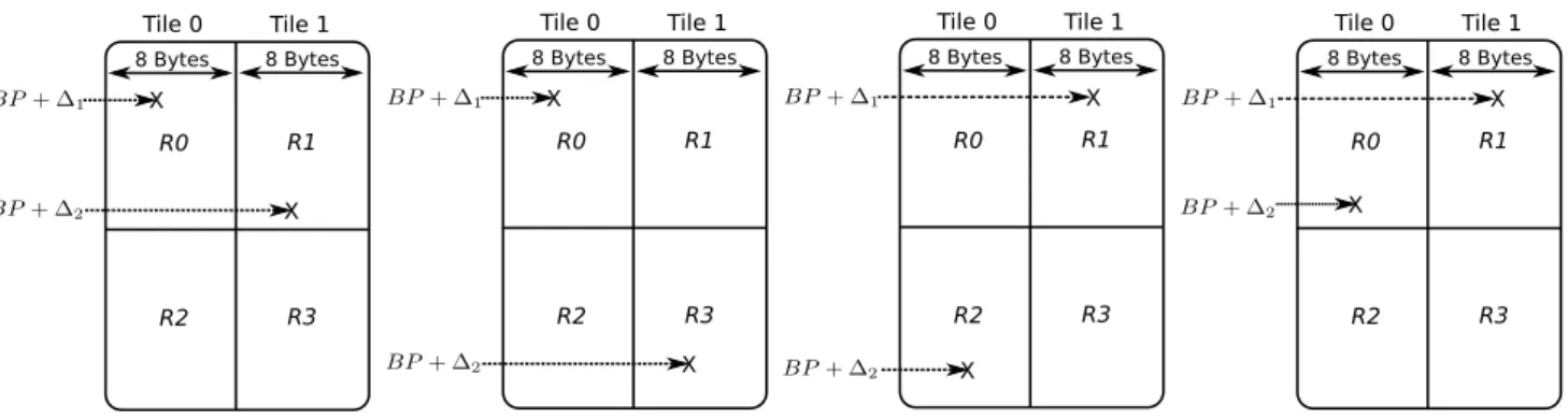
– Case A: (𝛥1&mask)! = (𝛥2&mask) . In this case, memory
objects of Inst1 and Inst2 belong to different tiles, guar-anteeing that they also belong to different regions, as shown in Fig. 4. Since the AAIS performs a non-equal-ity test on affinnon-equal-ity numbers, tile IDs can be appended to memory objects in place of region IDs in the affinity analysis step without the loss of correctness.
As the two memory objects belong to different regions and each region has its own set of memory ports, there is no architectural restriction on simultaneous execution of
Inst1 and Inst2. In this case, both BIS and AAIS
gener-ate the same instruction schedule. BIS schedules Instr1 and Instr2 in the same cycle without testing the second condition. On the other hand, AAIS detects that second condition is true and hence schedules the instructions in the same cycle.
Fig. 4 Different scenarios where two memory objects belong to different tiles. BP + 𝛥 is the address of a memory object, where BP is the base address and 𝛥 is the offset from BP
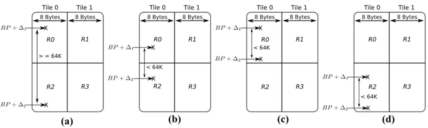
– Case B: (𝛥1&mask) = (𝛥2&mask) . In this case, memory
objects of Inst1 and Inst2 belong to the same tile, but they may or may not belong to the same region. This can be established by calculating the absolute difference between two offsets, i.e., Diff = abs(𝛥1− 𝛥2) . An
abso-lute difference of greater than or equal to the size of two regions (i.e., 64 K bytes) guarantees that the two memory objects belong to different regions in the same tile, as shown in Fig. 5a. However, there is no such guarantee when Diff is less than 64K bytes. Memory objects may (e.g., Fig. 5b) or may not (e.g., Fig. 5c, d) belong to dif-ferent regions in the same tile.
Since BP is not known at compile time, it is not pos-sible to calculate region numbers for the situations, as shown in Fig. 5b–d. Therefore, we pessimistically assume that the two memory objects belonging to the same tile always belong to the same region. In other words, like
Case A, we suggest appending the tile ID of a memory
object as its affinity number in the affinity analysis step. In the following discussion, we break Case B into two sub-cases and compare the AAIS with the BIS in each sub-case.
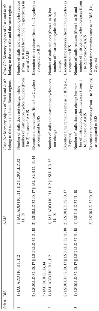
– Case B1: Memory objects belong to the same tile but
different regions. Table 2 compares three different BIS and AAIS-generated schedules for Case B. Let us assume that all three schedules are generated by BIS for the sce-nario, as depicted in Fig. 5a, b. BIS-generated instruction schedule 1 consists of one ADD instruction, two mem-ory instructions, and an SUB instruction. With memmem-ory objects located in different regions (of the same tile), scheduling of memory instructions by BIS in the same cycle (indicated by placing ∥ symbol between them in cycle 2) does not incur a stall. The BIS-generated sched-ule has an execution time of three cycles.
The corresponding AAIS-generated schedule is shown in the third column. Since memory objects belong to the same tile, the affinity analysis step pessimistically assumes that they also belong to the same region (which is not true) and appends their tile IDs as their affinity numbers. This makes the second condition to be false. As a result, AAIS serializes memory instructions by scheduling one of them in the same cycle with the ADD instruction and the other one with the SUB instruction. This reduces the execution time from 3 to 2 cycles as compared to BIS. Note that, SHAVE is a VLIW pro-cessor, capable of executing multiple instructions in the same cycle depending on the availability of functional units.
The BIS-generated instruction schedule two consists of one ADD instruction and two memory instructions. The schedule incurs no stall cycle and has an execution time of 2 cycles. As shown in the third column, AAIS serial-izes the two memory instructions by scheduling one of them with the ADD instruction. Although it changes the schedule as compared to BIS, the execution time remains the same as there is no change in the number of instruc-tion cycles and stalls.
The BIS-generated instruction schedule three consists of only two memory instructions. The schedule incurs no stall cycle and has an execution time of 1 cycle. On the other hand, AAIS serializes the two memory instructions by scheduling them in different cycles. This increases the execution time from 1 to 2 cycles as compared to BIS. In summary, AAIS in Case B1 does not change
the stall cycles as compared to BIS. However, it may increase, decrease, or not affect the number of instruc-tion cycles depending on the BIS-generated instrucinstruc-tion schedule.
(a)
(b)
(c)
(d)
Fig. 5 Different scenarios where two memory objects belong to the same tile. Figure 5a shows that absolute difference Diff between off-sets of two memory objects is greater than or equal to 64 K bytes, indicating that two memory objects belong to different regions.
Fig-ure 5b shows Diff less than 64 K bytes and memory objects belong to different regions. Figure 5c, d shows Diff less than 64 K bytes, but memory objects belong to the same region
– Case B2: Memory objects belong to the same tile and
the same region. Let us assume that all BIS schedules
shown in Table 2 are generated for the case, as depicted in Fig. 5c, d. With memory objects located in the same region (of the same tile), the two memory instructions scheduled in the same cycle by BIS in schedule 1 incur a stall. This results in total execution time of 4 cycles (i.e., three instruction cycles and one stall). In the cor-responding AAIS-generated schedule, affinity analysis step assumes that memory objects belonging to the same tile also belong to the same region (which is true in this case). As a result, AAIS serializes memory instructions by scheduling them in different cycles (with ADD and SUB instructions). This not only avoids the stall cycle, but also reduces the instruction cycles. Hence, the execu-tion time reduces from four to two cycles as compared to BIS.
The BIS-generated instruction schedule 2 incurs one stall cycle for two memory instructions scheduled in the same cycle. This results in an execution time of three cycles, i.e., two instruction cycles and one stall. However, AAIS serializes the two memory instructions by schedul-ing one of them with the ADD instruction. This saves the stall cycle and hence reduces the execution time from 3 to 2 cycles.
The BIS-generated instruction schedule 3 consists of only two memory instructions and incurs a single stall cycle, resulting in an execution time of two cycles. On the other hand, AAIS serializes the two memory instruc-tions by scheduling them in different cycles. This avoids the stall cycle but also increase the number of instruction cycles resulting in no effect on the execution time. In summary, AAIS in Case B2 reduces the stall cycles
as compared to BIS. However, it may increase, decrease, or not affect the number of instruction cycles depending on the BIS-generated instruction schedule.
It is clear from the above discussion that AAIS can reduce stall cycles when simultaneous accesses are requested into the same region of a tile. Furthermore, above discussion shows that tile IDs can be used as affin-ity numbers without the loss of correctness. It is impor-tant to mention that affinity numbers are merely used as a
compile time prediction for the physical location of mem-ory objects and do not provide any means of controlling data placement.
We propose two different approaches for the first step of our solution, i.e., affinity analysis. In the source code annotation approach, tile IDs are appended to memory objects by a programmer using custom attributes. In the automated analysis approach, tile IDs are inferred from the source code by analyzing the relative addresses of memory objects. Note that any one of these two approaches can be combined with the second step (i.e., AAIS) to construct the complete solution. Both approaches are discussed in the following subsections.
5.2.1 Source code annotation
It is a compile time approach that involves appending the tile ID to each memory object in the application source code. This is achieved by defining a custom attribute and making the compiler aware of its syntax and semantics.
In annotation-based approach, the difference between predicted and actual physical locations of memory objects depends upon the knowledge a programmer has about the layout of application data. Tile IDs can be appended more accurately by having a good understanding of data struc-tures used in the application and their access patterns. For example, tile IDs to be appended to array elements depend upon the location of the first element in a CMX slice (i.e., Tile 0/1), offset from the base address, and the byte alignment.
Figure 6 shows different predictions for physical loca-tions of array elements by appending tile IDs through source code annotation. The actual placement of array ele-ments in the CMX slice is shown in Fig. 6e. Let us assume that the BC simultaneously schedules the access to A[0] in the same cycle with A[3] and access to A[1] in the same cycle with A[2]. This will result in two stall cycles as two memory accesses will be blocked due to a clash between memory ports. In other words, this particular example has
optimization potential of 2. Figure 6b shows the best pre-diction of physical locations as it reflects the real mapping of array elements in the CMX slice.
(a) (b) (c) (d) (e)
5.2.2 Automated analysis
To avoid the modification of application source code and to automate the process of appending tile IDs to memory objects, we also propose the automated analysis. It is also a compile time approach like source code annotation.
Since the base address of a memory object is not known at compile time, the automated approach uses relative addresses for calculating tile IDs with the following assump-tions about data storage.
1. Data structures are stored in memory in a sequential manner.
2. The first element of a data structure is always located at the 16-byte boundary.
We propose an algorithm, shown in Algorithm 1, for auto-mated analysis of addresses and appending tile IDs to mem-ory objects. It is applicable only to data elements belonging to the same data structure and it operates on the level of each function independently.
Algorithm 1 operates as follows. For each memory instruction i in the function Func, the address of its mem-ory object is retrieved into memObject_i (lines 1–3) and then broken into the base address and the offset (line 4).
Table
2
Com
par
ison of AAIS wit
h BIS in Case B Sc h # BIS AAIS Case B1: Memor y objects of Ins t1 and Ins t2 belong t o t
he same tile but differ
ent r egions. Case B2: Memor y objects of Ins t1 and Ins t2 belong t o t
he same tile and t
he same r
egion.
1
1) IA
U.ADD I10, I11, I12
1) IA
U.ADD I10, I11, I12
∥ L SU1.LD.32 I1, I8 Number of s talls does no t c hang e, while number of ins truction cy cles r educes (fr om 3 t o 2) in case of AAIS Number of s
talls and ins
truction cy cles r educe (fr om 1 t o 0 and fr om 3 t o 2, r espectiv ely) in case of AAIS 2) L SU0.LD.32 I0, I7 ∥ L SU1.LD.32 I1, I8 2) L SU0.LD.32 I0, I7 ∥ IA
U.SUB I2, I3, I4
Ex ecution time r educes (fr om 3 t o 2 cy cles) as com par ed t o BIS Ex ecution time r educes (fr om 4 t o 2 cy cles) as com par ed t o BIS 3) IA
U.SUB I2, I3, I4
2
1) IA
U.ADD I10, I11, I12
1) IA
U.ADD I10, I11, I12
∥ L
SU1.LD.32
I1, I8
Number of s
talls and ins
truction cy cles does no t c hang e Number of s talls r educes (fr om 1 t o 0) but number of ins truction cy cles does no t chang e 2) L SU0.LD.32 I0, I7 ∥ L SU1.LD.32 I1, I8 2) L SU0.LD.32 I0, I7 Ex ecution time r
emains same as in BIS (i.e.,
2 cy cles) Ex ecution time r educes (fr om 3 t o 2 cy cles) as com par ed t o BIS 3 1) L SU0.LD.32 I0, I7 ∥ L SU1.LD.32 I1, I8 1) L SU1.LD.32 I1, I8 Number of s talls does no t c hang e but num -ber of ins truction cy cles incr eases (fr om 1 to 2) in case of AAIS Number of s talls r educes (fr om 1 t o 0) and number of ins truction cy cles incr eases (fr om 1 t o 2) in case of AAIS 2) L SU0.LD.32 I0, I7 Ex
ecution time incr
eases (fr om 1 t o 2 cy cles) as com par ed t o BIS Ex ecution time r
emains same as in BIS (i.e.,
2 cy
If not already appended with a tile ID, one is calculated for memObject_i (lines 5–7). Note that the width of each tile of a CMX slice is 8 bytes, as shown in Fig. 3b. Tile ID is decided based on the masking of offset value (i.e.,
Offset_memObject_i ) with 0 × 008. The inner for loop
(line 9–17) scans all other memory instructions in Func to find if they access a memory object with the same base address as memObject_i but with a different offset value. The condition of same base address ensures that memory objects belong to the same data structure. If the condi-tion is true and new memory object (i.e., memObject_j ) is not already appended with a tile ID, it is appended with a one based on masking of its offset value (i.e.,
Offset_memObject_j ) with 0 × 008.
5.2.3 Discussion
AAIS leads to the reduction of memory stalls only if an application has an inherent potential for optimization. If there are no simultaneous requests for accessing the same region of a CMX slice, there will be no stall cycles in the BIS-generated schedule and hence no space for AAIS to optimize the schedule. The optimization potential of an application can be defined as the number of simultaneous memory accesses to the same region scheduled in a single cycle by BIS. Optimization potential can easily be calcu-lated by inspecting the assembly code of an application generated by the BC.
To harness the optimization potential of an application, physical locations of memory objects predicted by affin-ity numbers and their actual physical locations should be same. Otherwise, appended tile IDs will provide wrong information to the scheduler for AAIS leading to the generation of an unoptimized or unwanted instruction schedule.
The source code annotation places a burden on the pro-grammer to attach custom attributes to memory objects. For large applications, it can be time-consuming and may also require modifications other than simply attach-ing custom attributes. However, if data placement can be enforced on the application data and it is a known priori, this approach could be more accurate and beneficial in reducing stall cycles than the automated one.
On the other hand, automated analysis relieves the pro-grammer from the manual modifications in the applica-tion source code. However, it appends tile IDs to memory objects based on their offset from the base address of data structure they belong to. It also assumes that the first ele-ment of a data structure is always aligned at the 16-byte boundary. This may result in appended tile IDs (i.e., pre-dicted physical locations) not reflecting the actual loca-tions of memory objects.
6 Implementation
In this section, we provide the details of modifications applied on Myriad 2 compiler to implement the proposed solution. We first explain the implementation of affin-ity analysis step using both approaches, followed by the implementation details of AAIS.
6.1 Source code annotation
Myriad 2 compiler is an extended version of LLVM com-piler framework that is tailored to generate code for a SHAVE processor. Like LLVM, Myriad 2 compiler also uses Clang as a compiler front-end for C/C++ languages. To implement the annotation-based approach, we modify the LLVM framework at two levels.
6.1.1 Adapting the front‑end
The idea of source code annotation is to allow the pro-grammer appending tile IDs to all memory objects in the application source code. We enable this by defining a cus-tom attribute for any type and making Clang aware of its syntax and semantics. We modify the Clang source code as described below.
1. Add the definition of the custom attribute to Clang. 2. Modify the relevant functions in Clang to detect if a
given variable declaration or initialization in the source code has the custom attribute defined in step 1. The vari-able can be of any type including the pointer varivari-able. 3. If a variable has the custom attribute, then attach the
metadata to the corresponding alloc, load, or store instructions generated for allocation or initialization of the variable.
6.1.2 Adapting the backend
The above-mentioned modifications enable the Clang to recognize custom attribute and take the appropriate actions to process it. However, the information needs to be propa-gated from the front-end to the backend.
In LLVM, selection DAG builder class builds an initial directed acyclic graph providing an abstraction for code representation [50]. We modify the relevant functions in the class to propagate the predicted physical locations of memory objects down to the post-register allocation scheduling (PostRAS) pass. This is achieved by detecting the existence of metadata of the desired kind while visiting
tile IDs are appended to memory objects of these instruc-tions based on the value of their metadata.
6.2 Automated analysis
Unlike the source code annotation, the automated analysis does not necessitate the modifications in front-end and the selection DAG builder class of the backend. We implement the automated analysis by writing a custom LLVM pass, named “Address Analysis Pass” (AAP), as shown in Fig. 7. AAP is invoked after register allocation and the generation of a basic instruction schedule. It calculates and appends tile IDs to memory objects by implementing Algorithm 1 and needs to be executed before the SHAVE PostRAS pass. Once the tile IDs are appended, SHAVE PostRAS pass cre-ates affinity-aware instruction schedule, as described in the following subsection.
6.3 Affinity‑aware instruction scheduling (AAIS)
In LLVM framework, the compiler consists of multiple passes which perform particular transformations and opti-mizations. In Myriad 2’s BC, a basic instruction schedule is generated by preceding passes before AAP, as shown in Fig. 7. We modify PostRAS pass to update basic instruc-tion schedule based on tile IDs appended to memory objects in AAP. The modified PostRAS pass detects the conflicts
among memory instructions by comparing tile IDs of their memory objects (i.e., testing the second condition defined in Sect. 5) and saves stall cycles by not scheduling them in the same clock cycle.
7 Experimental setup
To evaluate our proposed optimization, we used 11 bench-marks, as described in Sect. 3. Table 3 provides a brief description of these benchmarks, while the critical part of their source code is given in Table 4 of “Appendix”.
Benchmarks P1–P4 and P6 perform image addition or subtraction on different number and sizes of input images. Although a very basic operation, image addition, and sub-traction is used as a step in other algorithms. Example of such algorithms includes usage of image differencing as a simple technique for change detection [51] providing a powerful interpretation of change in the tropical region and urban environment [52]. Image differencing is also used in mask mode radiography (for studying the propagation of contrast medium) and in motion-based segmentation [41]. Similarly, image addition is used in calculating the average face as a step in face recognition techniques based on eigen-faces [53]. The integral image technique is another algorithm which uses the pixel addition and is widely used in fields of computer vision and computer graphics such as texture mapping and face detection [54, 55].
Benchmark P5 and P8 perform filtering operation, while P7 represents convolution. These operations are widely used for noise reduction, sharpening, edge detection, and blurring of images [41, 56]. Benchmark P9 represents white balanc-ing operation which is a required stage of image-processbalanc-ing pipeline in modern digital cameras [57, 58]. Benchmark P10 consists of histogram generation which is used as an initial step in image enhancement applications [59, 60]. Benchmark
Fig. 7 Implementation of automated analysis as a custom pass in
LLVM. Address analysis pass (AAP) appends affinity numbers to memory objects using Algorithm 1. Modified SHAVE PostRAS pass creates affinity-aware instruction schedule based on affinity numbers
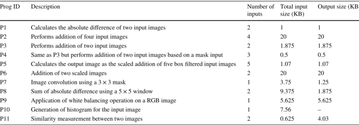
Table 3 Brief description of benchmarks
Prog ID Description Number of
inputs Total input size (KB) Output size (KB)
P1 Calculates the absolute difference of two input images 2 1 1
P2 Performs addition of four input images 4 20 20
P3 Performs addition of two input images 2 1.875 1.875
P4 Same as P3 but performs addition of two input images based on a mask input 3 0.5 0.5
P5 Calculates the output image as the scaled addition of five box filtered input images 5 1.07 1.07
P6 Addition of two scaled images 2 20 20
P7 Image convolution using a 3 × 3 mask 1 3.75 1.25
P8 Sum of absolute difference using a 5 × 5 window 2 9.375 1.875
P9 Application of white balancing operation on a RGB image 1 5.625 5.625
P10 Generation of histogram for the input image 1 7.56 –
P11 measures the degree of similarity for a given pixel in the first image with pixels in the second image at different disparities. The similarity measurement is an important step in all stereo-matching algorithms [46, 61].
All benchmarks were executed on a Myriad 2 board with a single execution thread using both BC and AAC. For each benchmark, we measured the performance improvement as the percentage reduction in stall cycles and execution time when compared to the BC.
8 Evaluation
As mentioned in Sect. 5.2.3, source code annotation is a time-consuming process and may need modifications at many places in the application source code. Therefore, we evaluate and demonstrate its working only for a single memory-intensive test program in the following subsection.
8.1 Source code annotation for a simple memory‑intensive test program
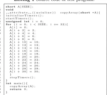
Listing 1 shows the source code of a simple test program. The program defines an array of short type of length SIZE. The main() function calls the copyArray() function which writes to every second element of the array. For per-formance evaluation, stalls and instruction execution cycles are measured for the for loop of copyArray() function.
A portion of assembly code generated by BC for Listing 1 is shown in Fig. 8a. In SHAVE’s assembly, instructions scheduled in the same cycle are represented by placing ∥ symbol among them. The syntax of a Store instruction is LSU(0|1).STO.16 x,y,imm, and it moves the data from the register x to memory. The memory address is
calculated using the content of the register y as the base address and imm as the displacement.
1 short A [ SIZE ] ; 2 void 3 a t t r i b u t e ( ( n o i n l i n e ) ) copyArray ( short A) { 4 i n i t i a l i z e T i m e r s ( ) ; 5 s t a r t T i m e r s ( ) ; 6 unsigned i n t i = 0 ; 7 f o r ( i = 0 ; i < SIZE ; i += 3 2 ) { 8 A [ i ] = 0 ; 9 A [ i + 2 ] = 2 ; 10 A [ i + 4 ] = 4 ; 11 A [ i + 6 ] = 6 ; 12 A [ i + 8 ] = 8 ; 13 A [ i + 1 0 ] = 1 0 ; 14 A [ i + 1 2 ] = 1 2 ; 15 A [ i + 1 4 ] = 1 4 ; 16 A [ i + 1 6 ] = 1 6 ; 17 A [ i + 1 8 ] = 1 8 ; 18 A [ i + 2 0 ] = 2 0 ; 19 A [ i + 2 2 ] = 2 2 ; 20 A [ i + 2 4 ] = 2 4 ; 21 A [ i + 2 6 ] = 2 6 ; 22 A [ i + 2 8 ] = 2 8 ; 23 A [ i + 3 0 ] = 3 0 ; 24 } 25 s t o p T i m e r s ( ) ; 26 } 27 i n t main ( ) { 28 copyArray (A) ; 29 return 0 ; 30 } * Listing 1 Source code of test program.
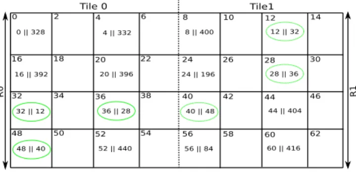
In the assembly code of Fig. 8a, i25 is a register contain-ing the value of base_address + 64 . Numbers on the right of the assembly code show the clock cycles in which instruc-tions are scheduled. For ease of discussion, we assume that base_address is zero. In cycle 1 of the assembly code, two Store instructions are scheduled simultaneously. One of them accesses address 60 (= 0 + 64 − 4), located in
Tile 1 and R1 of the CMX slice, as shown in Fig. 8b. The other paired instruction accesses the location at address 8 (= 0 + 64 − 56), also located in the same tile and the same region. As a result, the simultaneous scheduling of the two
(a)
(b)
instructions incurs a stall cycle, as discussed in Case B2 of section 5.2. Same is true for cycles 4, 5, and 6.
On the other hand, the two store instructions scheduled in cycle 2 access addresses in different tiles and hence differ-ent regions. Specifically, one of them accesses the address 12 (=0+64 − 52), located in the Tile 1 and R1. The other paired instruction accesses the address 16 (= 0 + 64 − 48), located in the Tile0 and R0. Therefore, simultaneous sched-uling does not incur a stall cycle as discussed in Case A of section 5.2. Same is true for cycles 3, 7, and 8. Note that the optimization potential for the given piece of assembly code shown in Fig. 8a (and not for the whole program) is 4 as there are four cycles entertaining simultaneous memory accesses to the same region. The analysis of all (SIZE = 2500) memory accesses shows that the program of Listing 1 has an optimization potential of 234 cycles.
Listing 2 is functionally same as the Listing 1, but the source code is modified to append memory objects with their tile IDs. Line 1 and 2 define two macros, Tile0 and Tile1, using the custom defined attribute, i.e., movi-Attr. As shown in lines 13–28, instead of accessing the array elements through array index, each element is accessed using a pointer carrying a tile ID of 0 or 1.
1 #d e f i n e T i l e 0 a t t r i b u t e ( ( moviAttr ( 0 ) ) ) 2 #d e f i n e T i l e 1 a t t r i b u t e ( ( moviAttr ( 1 ) ) ) 3 short A [ SIZE ] ;
4 void a t t r i b u t e ( ( n o i n l i n e ) ) copyArray ( short A) { 5 i n i t i a l i z e T i m e r s ( ) ;
6 s t a r t T i m e r s ( ) ;
7 T i l e 0 short temp1 , temp2 ; 8 T i l e 1 short temp3 , temp4 ; 9 unsigned i n t i = 0 ; 10 f o r ( i = 0 ; i < SIZE ; i += 3 2 ) { 11 temp1 = A + i ; temp1 = 0 ; 12 temp2 = A + i + 2 ; temp2 = 2 ; 13 temp3 = A + i + 4 ; temp3 = 4 ; 14 temp4 = A + i + 6 ; temp4 = 6 ; 15 temp1 = A + i + 8 ; temp1 = 8 ; 16 temp2 = A + i + 1 0 ; temp2 = 1 0 ; 17 temp3 = A + i + 1 2 ; temp3 = 1 2 ; 18 temp4 = A + i + 1 4 ; temp4 = 1 4 ; 19 temp1 = A + i + 1 6 ; temp1 = 1 6 ; 20 temp2 = A + i + 1 8 ; temp2 = 1 8 ; 21 temp3 = A + i + 2 0 ; temp3 = 2 0 ; 22 temp4 = A + i + 2 2 ; temp4 = 2 2 ; 23 temp1 = A + i + 2 4 ; temp1 = 2 4 ; 24 temp2 = A + i + 2 6 ; temp2 = 2 6 ; 25 temp3 = A + i + 2 8 ; temp3 = 2 8 ; 26 temp4 = A + i + 3 0 ; temp4 = 3 0 ; 27 } 28 s t o p T i m e r s ( ) ; 29 } 30 i n t main ( ) { 31 copyArray (A) ; 32 return 0 ; 33 } * * ** * * * * * * * * * * * * * * * * * Listing 2 Source code of test program with static affin-ity allocation.
Figure 9a shows a portion of assembly code generated by AAC for the Listing 2, where register i18 contains the value of base_address + 256 . For ease of discussion, we assume that base_address is zero. The layout of array ele-ments in the CMX slice is shown in Fig. 9b. Assuming that the first element of the array is located at the address zero, the 16th element has an address of 32 (= 16 × 2, where 2 is the size of each element) and the 18th element has an address of 36. Since lines 21 and 22 of Listing 2 append the same tile ID to 16th and 18th array elements, AAC does not schedule accesses to them in the same cycle. As shown in Fig. 9a, address 32 (= 256 − 224) is accessed simultane-ously with address 12 (= 256 − 244) in cycle 10 and both addresses are located in different tiles and hence different regions. This saves a stall cycle for accessing the 16th array
(a) (b)
element (located at address 32) as compared to the schedule generated by BC, as shown in Fig. 8. In the same way, all the other stall-generating simultaneous accesses in Fig. 8 are avoided, resulting in significant reduction of stall cycles for the annotated version of the program.
Execution of the test program in Listing 1 on Myriad 2 board takes 937 clock cycles (i.e., 765 instruction cycles plus 172 stalls). On the other hand, the test program of List-ing 2 takes 697 clock cycles (i.e., 641 instruction cycles plus 56 stalls). The remaining 56 stalls may belong to categories of bad speculation or core bound stalls. The difference of 240 cycles between the two execution times is very close to the optimization potential of 234 cycles for the test pro-gram in Listing 1. The significant improvement by 25.61% in execution time of the sample test program can be attributed to its memory-intensive nature.
8.2 Experimental results for automated affinity analysis
In this subsection, we evaluate the classification of memory references using automated affinity analysis approach. We executed the benchmarks given in Table 3 on a Myriad 2 board using both BC and AAC.
Figure 10 shows the breakdown of the execution time of benchmarks into instruction and stall cycles. The breakdown
is shown for both, BC and AAC. Benchmarks executed using AAC show a significant reduction in stall cycles as com-pared to the BC (e.g., P1, P2, P3, P4, P6, P9, and P10). The average reduction in stall cycles is by 69.83%.
Some benchmarks, such as P5 and P7, show a relatively lesser reduction in stall cycles. The difference in reduction of stall cycles across different benchmarks can be explained through their optimization potential. Figure 11 shows the breakdown of total requests for simultaneous memory access into three different cases. As explained in Sect. 5.2.3, BC and AAC generate the same schedule in Case A. In Case
B1, AAC can possibly reduce the number of instruction
cycles. However, AAC also reduces stalls in addition to a possible reduction in the number of instruction cycles in
Case B2. In other words, higher the number of simultaneous
memory requests belonging to Case A lower is the
Optimi-zation Potential of a benchmark. Figure 11 shows that both benchmarks, P5 and P7, have 20% of simultaneous memory requests belonging to Case A. Therefore, AAC achieves relatively lower reduction in stall cycles for P5 and P7 as compared to other benchmarks.
For most benchmarks (i.e., P1, P3, P4, P5, P6, P7, P9, and P10), the number of instruction cycles remains almost same when executed using BC and AAC. However, AAC execution of P2 increases the number of instruction cycles by 4.83%. The increase can be attributed to those
Fig. 10 Breakdown of execution time into instruction and stall cycles for executions using BC and AAC
Fig. 11 Breakdown of simultaneous memory access into three different cases. Case A: Memory objects belong to different tiles. Case B: Mem-ory object belong to the same tile but different regions. Case B_2: MemMem-ory objects belong to the same region of the same tile
simultaneously scheduled memory instructions in the BC-generated schedule which cannot be successfully serialized by AAC through scheduling them in the same cycle with another suitable instruction. As a result, new cycles need to be inserted for scheduling of such instructions (as explained through Schedule 3 of Table 2 in Sect. 5). On the other hand, AAC execution of P8 and P11 shows 2.34% and 24.57% reduction in instruction cycles, respectively, as compared to BC. This reduction can be attributed to those simultane-ously scheduled memory instructions in the BC-generated schedule which are successfully serialized by AAC through scheduling them in the same cycle with another suitable instruction (as explained through the Schedule 1 of Table 2
in Sect. 5).
Figure 10 shows that stall cycles make up to 8.77% (i.e., P11) of execution time and 4% on average for BC execu-tions. Since our proposed optimization focuses only on the reduction of memory stalls, the execution time improves up to 30% (i.e., P11) with an average of 5.79%. However, the significant average reduction by 69% in stall cycles suggests that the proposed optimization can substantially improve execution time for memory-intensive applications, as shown by a sample program in Sect. 8.1.
9 Conclusion
In this paper, we propose the classification of memory ref-erences as a compiler optimization to reduce the memory bound stalls incurred by an application running on a vision-processing system (i.e., Myriad 2 MPSoC). Our solution consists of two steps: affinity analysis and affinity-aware
instruction scheduling. We implemented two different approaches for affinity analysis, namely, source code anno-tation and automated analysis.
While source code annotation approach facilitates more accurate prediction of the physical location of memory objects, it needs considerable effort by the programmer to modify the source code. On the other hand, automated analy-sis relieves a programmer from the burden of modifying the source code, but employs certain assumptions about data placement. This may result with less accuracy in attaching affinity numbers to memory objects.
Experimental results show that by making the compiler aware of memory architecture and efficiently using the dual load-store units, memory stalls can be reduced significantly. Classification of memory references using source code anno-tation reduces stalls by 67.44% for a memory-intensive pro-gram, leading to 25.61% improvement in its execution time. On the other hand, automated analysis approach shows an average reduction by 69.83% in stall cycles with a modest improvement by 5.79% in execution time over a set of eleven different image-processing benchmarks.
Acknowledgements This work is supported by European Union’s Horizon2020 research and innovation programme under grant agree-ment number 687698 and Ph.D. scholarship from Higher Education Commission (HEC) of Pakistan awarded to Naveed Ul Mustafa.
Appendix: A critical part of source code
for benchmarks
Table 4 Source code of benchmarks Prog
ID Critical code ProgID Critical code
P1 f o r ( j = 0 ; j < width ; j ++){ i f ( i n 1 [ j ] > i n 2 [ j ] ) out [ 0 ] [ j ] = i n 1 [ j ] − i n 2 [ j ] ; e l s e out [ 0 ] [ j ] = i n 2 [ j ] − i n 1 [ j ] ; } P2 f o r ( unsigned i n t k = 0 ; k < width ; k++){ f o r ( unsigned i n t d i s p = 0 ; d i s p < d i s p a r i t i e s ; d i s p ++){ out [ k d i s p a r i t i e s + d i s p ] = ( path0 [ k d i s p a r i t i e s + d i s p ] + path1 [ k d i s p a r i t i e s + d i s p ] + path2 [ k d i s p a r i t i e s + d i s p ] + path3 [ k d i s p a r i t i e s + d i s p ] ) / 4 ; } } P3 f o r ( i = 0 ; i < ( i n t ) width ; i ++){ add = s r c 1 [ 0 ] [ i ] + s r c 2 [ 0 ] [ i ] ; i f ( add >= 2 5 5 ) add = 2 5 5 . 0 f ; i f ( add <= 0 ) add = 0 . 0 f ;
d s t [ 0 ] [ i ] = ( unsigned char ) ( add ) ; } P4 f o r ( i = 0 ; i < ( i n t ) width ; i ++) { i f ( mask [ 0 ] [ i ] > 0 ) { add = s r c 1 [ 0 ] [ i ] + s r c 2 [ 0 ] [ i ] ; i f ( add >= 2 5 5 ) add = 2 5 5 . 0 f ; i f ( add <= 0 ) add = 0 . 0 f ; d s t [ 0 ] [ i ] = ( u8 ) ( add ) ; } } P5 f o r ( i = 0 ; i < width ; i ++){ sum = 0 ; f o r ( y = 0 ; y < 5 ; y++){ f o r ( x = −2; x <= 2 ; x++){ sum += ( l i n e s [ y ] [ x ] ) ; } l i n e s [ y ]++; }
( out+i ) =(u8 ) ( ( ( h a l f ) ( f l o a t ) sum ) ( h a l f ) 0 . 0 4 ) ; } P6 f o r ( c o l = 0 ; c o l < width ; c o l ++){ f o r ( d i s p = 0 ; d i s p < d i s p a r i t i e s ; d i s p ++){ r e s u l t = ( a l p h a d i s p a r i t y C o s t [ c o l d i s p a r i t i e s + d i s p ] + b e t a adCost [ c o l d i s p a r i t i e s + d i s p ] ) / normFactor ; i f ( r e s u l t > 2 5 5 ) r e s u l t = 2 5 5 ; d i s p a r i t y C o s t [ c o l d i s p a r i t i e s + d i s p ] = r e s u l t ; } } P7 f o r ( i = 0 ; i < inWidth / 3 ; i ++){ sum = 0 . 0 f ; f o r ( x = 0 ; x < 3 ; x++) { f o r ( y = 0 ; y < 3 ; y++) sum += ( short f l o a t ) ( l i n e s [ x ] [ y − 1 ] conv [ x 3 + y ] ) ; l i n e s [ x ]+=3; }
out [ 0 ] [ i ] = ( short f l o a t ) ( sum ) ; } P8 f o r ( i = 0 ; i < width ; i ++){ sum = 0 ; f o r ( x = 0 ; x < 5 ; x++){ f o r ( y = 0 ; y < 5 ; y++){ d i f f = l i n e s 1 [ x ] [ y − 2 ] − l i n e s 2 [ x ] [ y − 2 ] ; i f ( d i f f < 0 ) d i f f = 0 − d i f f ; sum += d i f f ; } l i n e s 1 [ x ]++; l i n e s 2 [ x ]++; } i f ( sum >= 2 5 5 ) sum = 2 5 5 ;
out [ 0 ] [ i ] = ( unsigned char ) ( sum ) ; } P9 f o r ( i = 0 ; i < ( i n t ) width ; i ++){ r = ( ( unsigned i n t ) r I n [ i ] ( unsigned i n t ) awbCoef [ 0 ] ) >> 1 5 ; g = ( ( unsigned i n t ) g I n [ i ] ( unsigned i n t ) awbCoef [ 1 ] ) >> 1 5 ;
b = ( ( unsigned i n t ) bIn [ i ] ( unsigned i n t ) awbCoef [ 2 ] ) >> 1 5 ;
rOut [ i ] = ( unsigned short ) ( r > clamp [ 0 ] ? clamp [ 0 ] : r ) ;
gOut [ i ] = ( unsigned short ) ( g > clamp [ 0 ] ? clamp [ 0 ] : g ) ;
bOut [ i ] = ( unsigned short ) ( b > clamp [ 0 ] ? clamp [ 0 ] : b ) ; } P10 f o r ( i = 0 ; i < width ; i +=4){ i n t o u t 1 = p i H i s t 1 ; i n t o u t 2 = p i H i s t 2 ; i n t o u t 3 = p i H i s t 3 ; i n t o u t 4 = p i H i s t 4 ; p i H i s t 1 = o u t 1 +1; p i H i s t 2 = o u t 2 +1; p i H i s t 3 = o u t 3 +1; p i H i s t 4 = o u t 4 +1; p i H i s t 1 = h i s t 1 + i n d e x 1 ; p i H i s t 2 = h i s t 2 + i n d e x 2 ; p i H i s t 3 = h i s t 3 + i n d e x 3 ; p i H i s t 4 = h i s t 4 + i n d e x 4 ; i n d e x 1 = ( unsigned i n t ) i n l i n e [ i + 8 ] ; i n d e x 2 = ( unsigned i n t ) i n l i n e [ i + 9 ] ; i n d e x 3 = ( unsigned i n t ) i n l i n e [ i + 1 0 ] ; i n d e x 4 = ( unsigned i n t ) i n l i n e [ i + 1 1 ] ; } P11 f o r ( i n t p o s i t i o n L = 0 ; p o s i t i o n L < ( width&0 x f f f f f f f c ) ; p o s i t i o n L ++) { unsigned i n t in1L = i n 1 [ p o s i t i o n L ] ; unsigned i n t i n p u t [ DISPARITIES ] ; #pragma u n r o l l DISPARITIES f o r ( i n t i = DISPARITIES−4; i >= 0 ; i −=4) ( ( u i n t 4 ) &i n p u t [ i ] ) = ( ( u i n t 4 ) &i n 2 [ p o s i t i o n L −i −3])−> s 3 2 1 0 ; #pragma u n r o l l DISPARITIES f o r ( unsigned i n t indexR = 0 ;
indexR < DISPARITIES ; indexR ++) {
unsigned i n t resultXOR = in1L ˆ i n p u t [ indexR ] ;
s t d : : b i t s e t <32> b i t s = resultXOR ; out [ p o s i t i o n L DISPARITIES +
indexR ] = ( unsigned char ) b i t s . c o u n t ( ) ; } } * * * * * * * * * * * * * * * * * * * * * * * * * * * * * *
References
1. Pulli, K., Baksheev, A., Kornyakov, K., Eruhimov, V.: Real-time computer vision with opencv. Commun. ACM 55(6), 61–69 (2012)
2. Farabet, C., Martini, B., Corda, B., Akselrod, P., Culurciello, E., LeCun, Y.: Neuflow: a runtime reconfigurable dataflow processor for vision. In: Proceedings of IEEE Computer Society Confer-ence on Computer Vision and Pattern Recognition Workshops (CVPRW), pp. 109–116 (2011)
3. Barry, B., Brick, C., Connor, F., Donohoe, D., Moloney, D., Rich-mond, R., O’Riordan, M.J., Toma, V.: Always-on vision process-ing unit for mobile applications. IEEE Micro. 35(2), 56–66 (2015) 4. Chua, J.L., Chang, Y.C., Lim, W.K.: A simple vision-based fall
detection technique for indoor video surveillance. Signal Image Video Process. 9(3), 623–633 (2015)
5. Gómez, M.J., García, F., Martín, D., de la Escalera, A., Armin-gol, J.M.: Intelligent surveillance of indoor environments based on computer vision and 3D point cloud fusion. Exp. Syst. Appl.
42(21), 8156–8171 (2015)
6. Rautaray, S.S., Agrawal, A.: Vision based hand gesture recogni-tion for human computer interacrecogni-tion: a survey. Artif. Intell. Rev.
43(1), 1–54 (2015)
7. Suwajanakorn, S., Kemelmacher-Shlizerman, I., Seitz, S.M.: Total moving face reconstruction. In: Proceedings of European Confer-ence on Computer Vision, pp. 796–812 (2014)
8. Smolyanskiy, N., Huitema, C., Liang, L., Anderson, S.E.: Real-time 3D face tracking based on active appearance model con-strained by depth data. Image Vis. Comput. 32(11), 860–869 (2014)
9. Bar. Y., Diamant, I., Wolf, L., Greenspan, H.: Deep learning with non-medical training used for chest pathology identification. In: Proceedings of Medical Imaging 2015: Computer-Aided Diagno-sis (2015)
10. Greenspan, H., van Ginneken, B., Summers, R.M.: Guest editorial deep learning in medical imaging: overview and future promise of an exciting new technique. IEEE Trans. Med. Imaging. 35(5), 1153–1159 (2016)
11. Ohn-Bar, E., Tawari, A., Martin, S., Trivedi, M.M.: On surveil-lance for safety critical events: in-vehicle video networks for pre-dictive driver assistance systems. Comput. Vis. Image Underst.
134, 130–140 (2015)
12. Mandal, D.K., Sankaran, J., Gupta, A., Castille, K., Gondkar, S., Kamath, S., Sundar, P., Phipps, A.: An Embedded Vision Engine (EVE) for automotive vision processing. In: Proceedings of IEEE International Symposium on Circuits and Systems (ISCAS), pp. 49–52 (2014)
13. Zhang, B., Huang, W., Li, J., Zhao, C., Fan, S., Wu, J., Liu, C.: Principles, developments and applications of computer vision for external quality inspection of fruits and vegetables: a review. Food Res. Int. 62, 326–343 (2014)
14. Aghbashlo, M., Hosseinpour, S., Ghasemi-Varnamkhasti, M.: Computer vision technology for real-time food quality assurance during drying process. Trends Food Sci. Technol. 39(1), 76–84 (2014)
15. Ma, J., Sun, D.W., Qu, J.H., Liu, D., Pu, H., Gao, W.H., Zeng, X.A.: Applications of computer vision for assessing quality of agri-food products: a review of recent research advances. Crit. Rev. Food Sci. Nutr. 56(1), 113–127 (2016)
16. Guo, Y., Zhuge, Q., Hu, J., Yi, J., Qiu, M., Sha, E.H.M.: Data placement and duplication for embedded multicore systems with scratch pad memory. IEEE Trans. Comput. Aided Des. Integr. Circuits Syst. 32(6), 809–817 (2013)
17. Wang, D., Du, X., Yin, L., Lin, C., Ma, H., Ren, W., Wang, H., Wang, X., Xie, S., Wang, L., Liu. Z., Wang, T., Pu, Z., Ding, G.,
Zhu, M., Yang, L., Guo, R., Zhang, Z., Lin, X., Hao, J., Yang, Y., Sun, W., Zhou, F., Xiao, N., Cui, Q., Wangg, X.: MaPU: A novel mathematical computing architecture. In: Proceedings of IEEE International Symposium on High Performance Computer Architecture (HPCA), pp. 457–468 (2016)
18. Lin, Z., Sankaran, J., Flanagan, T.: Empowering automotive vision with TI’s Vision AccelerationPac. TI White Paper (2013) 19. Conti, F., Rossi, D., Pullini, A., Loi, I., Benini, L.: PULP: a
ultra-low power parallel accelerator for energy-efficient and flexible embedded vision. J. Signal Process. Syst. 84(3), 339–354 (2016) 20. Machine Vision Technology: Movidius https ://www.movid ius.
com/techn ology . Accessed 23 Sept 2017
21. Diken, E., O’Riordan, M.J., Jordans, R., Jozwiak, L., Corporaal, H., Moloney, D.: Mixed-length simd code generation for vliw architectures with multiple native vector-widths. In: Proceedings of IEEE 26th International Conference on Application-specific Systems, Architectures and Processors (ASAP), pp. 181–188 (2015)
22. Chen, T.P., Budnikov, D., Hughes, C.J, Chen, Y.K.: Computer vision on multi-core processors: articulated body tracking. In: Proceedings of IEEE International Conference on Multimedia and Expo, pp. 1862–1865 (2007)
23. Lattner, C., Adve, V.: LLVM: A compilation framework for lifelong program analysis & transformation. In: Proceedings of Second Annual IEEE/ACM International Symposium on Code Generation and Optimization (CGO), pp. 75–88 (2004)
24. Sethia, A., Dasika, G., Mudge, T., Mahlke, S.A.: Customized processor for energy efficient scientific computing. IEEE Trans. Comput. 61(12), 1711–1723 (2012)
25. Cho, J., Paek, Y., Whalley, D.: Efficient register and memory assignment for non-orthogonal architectures via graph coloring and MST algorithms. In: Proceedings of the Joint Conference on Languages, Compilers and Tools for Embedded Systems: Soft-ware and Compilers for Embedded Systems (LCTES/SCOPES), pp. 130–138 (2002)
26. Leupers, R., Kotte, D.: Variable partitioning for dual memory bank DSPs. In: Proceedings of IEEE International Conference on Acoustics, Speech, and Signal Processing (ICASSP), pp. 1121– 1124 (2001)
27. Ko, M.Y., Bhattacharyya, S.S.: Partitioning for DSP software syn-thesis. In: Proceedings of International Workshop on Software and Compilers for Embedded Systems (SCOPES), pp. 344–358 (2003) 28. Murray, A., Franke, B.: Fast source-level data assignment to
dual memory banks. In: Proceedings of the 11th International Workshop on Software and Compilers for Embedded Systems (SCOPES), pp. 43–52 (2008)
29. Sipkova, V.: Efficient variable allocation to dual memory banks of DSPs. In: Proceedings of International Workshop on Software and Compilers for Embedded Systems (SCOPES), pp. 359–372 (2003)
30. Kim, Y., Lee, J., Shrivastava, A., Paek, Y.: Operation and data mapping for CGRAs with multi-bank memory. In: Proceedings of the ACM SIGPLAN/SIGBED Conference on Languages, Compilers, and Tools for Embedded Systems (LCTES), pp. 17–26 (2010)
31. Mi, W., Feng, X., Xue, J., Jia. Y.: Software-hardware cooperative DRAM bank partitioning for chip multiprocessors. In: Proceed-ings of International Conference on Network and Parallel Comput-ing (IFIP), pp. 329–343 (2010)
32. Bircsak, J., Craig, P., Crowell, R., Cvetanovic, Z., Harris, J., Nel-son, C.A, Offner, C.D.: Extending openmp for NUMA machines. In: Proceedings of ACM/IEEE 2000 Conference on Supercomput-ing (SC) (2000)
33. Antony, J., Janes, P.P., Rendell, A.P.: Exploring thread and mem-ory placement on numa architectures: Solaris and linux, ultras-parc/fireplane and opteron/hypertransport. In: Proceedings of