852 IEEE TRANSACTIONS ON ANTENNAS AND PROPAGATION, VOL. 62, NO. 2, FEBRUARY 2014
Scattering From an Impedance Object at the Edge of
a Perfectly Conducting Wedge
Behnam Ghassemiparvin, Student Member, IEEE, and Ayhan Altintas, Senior Member, IEEE
Abstract—In this study, scattering from impedance bodies po-sitioned at the edge of a perfectly electrically conducting wedge is investigated. In the treatment of the problem, eigenfunction ex-pansion in terms of spherical vector wave functions is employed. A complete dyadic Green’s function for the spherical impedance boss at the edge is developed. It is observed that the scattering is highly enhanced by the edge guided waves. Additionally, using T-matrix method, the solution is extended to the general case of irregularly shaped scatterers. The T-matrix solution is verified by applying it to the case of a spherical scatterer and results are compared with the dyadic Green’s function solution.
Index Terms—Dyadic Green’s function, electromagnetic scattering, spherical vector wave functions, T-matrix, wedge scattering.
I. INTRODUCTION
T
HIS paper is mainly concerned with the development of an analytical solution for scattering from an impedance object at the edge of a perfectly conducting wedge. Scattering from several configurations of spherical and irregularly shaped objects are considered which will serve to provide a basis to extend the scope of current high-frequency techniques for scat-terers at the edge. In addition, this work is a first step toward an analytical solution for scattering from a rough or corrugated edge.In the literature, the problem of cylinder-tipped half plane is first considered by Keller in which the Geometrical Theory of Diffraction (GTD) solution is presented [1]. Shortcomings of the Keller’s theory in the transition regions were overcome by incorporating higher order terms in the solution, hence, con-tinuous fields at the boundaries are obtained [2]. For the gen-eral case of cylinder-tipped wedge, using GTD approach, an asymptotic expression of Green’s function is obtained in [3]. Scattering from slotted and corrugated wedges which are of im-portance in analyzing aperture antennas and radar targets are investigated in [4]–[9]. For canonical problems, series solutions in terms of eigenfunctions are presented [7]–[9]. For irregularly shaped slot configurations, based on application of equivalence
Manuscript received April 20, 2013; revised October 01, 2013; accepted Oc-tober 23, 2013. Date of publication November 08, 2013; date of current version January 30, 2014.
B. Ghassemiparvin is with the Department of Electrical and Elec-tronics Engineering, Bilkent University, Ankara 06800, Turkey (e-mail: [email protected]).
A. Altintas is with the Department of Electrical and Electronics Engineering, Bilkent University, TR-06800 Bilkent, Ankara, Turkey and also with the Com-munication and Spectrum Management Research Center (ISYAM), Bilkent Uni-versity, Ankara, Turkey (e-mail: [email protected]).
Digital Object Identifier 10.1109/TAP.2013.2290115
principle, the problem is divided into distinct exterior and inte-rior domains. Exteinte-rior problem is concerned with wedge scat-tering which is formulated using UTD or Green’s function ex-pansion. Interior problem of cavity is treated by employing fi-nite element method [4]–[6]. Published works mostly refer to configurations which conform to cylindrical coordinates and do not consider the scattering from structures at the edge. How-ever, scattering from perfectly conducting wedge is considered in [10] where dyadic Green’s function (DGF) in terms of spher-ical vector wave functions are obtained. This dyadic Green’s function is essential for analyzing the scattering from objects near the edge, since it gives accurate results in the paraxial re-gion. In addition it can be used with the T-matrix method to an-alyze the scattering from irregularly shaped objects on the edge. For the problem of rough edge diffraction, solutions using asymptotic physical optics approach are presented in [11], [12]. These solutions are limited to the knife edge case and away from shadow boundaries.
In this work, we present an analytical solution in terms of the T-matrix for an irregularly shaped impedance object positioned at the edge of a perfectly electrically conducting (PEC) wedge. This solution is valid almost everywhere for various wedge an-gles. Also, the T-matrix solution is independent of the source. This analytical solution will provide an physical insight to the scattering mechanism and it can be extended for multiple scat-terers in order to simulate a rough edge.
In Section I the scattering problem is stated. Analysis is carried out in three steps. First, dyadic Green’s function for the spherical impedance boss at the edge is formulated in terms of spherical vector wave functions in Section II. This exact solution is then used to verify the T-matrix method for irregularly shaped scatterers which is developed in Section III. In Section IV, numerical results are presented for T-matrix where the solution is verified by comparing it with the dyadic Green’s function solution. Concluding remarks are presented in Section V. Throughout this paper an time convention is used and suppressed.
II. STATEMENT OF THEPROBLEM
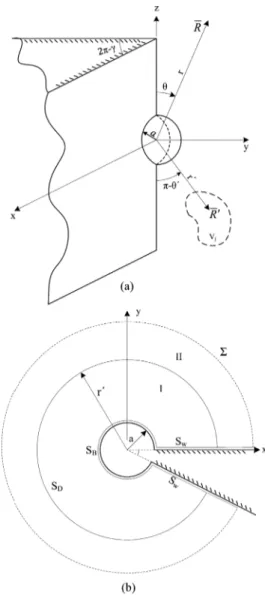
Geometry of the problem is shown in Fig. 1. A perfectly elec-trically conducting (PEC) wedge with exterior angle is consid-ered which extends infinitely in the direction. One side of the wedge lies on the plane. An irregularly shaped impedance scatterer is positioned at the edge of the PEC wedge. Position vectors, and , denote the observation and the source locations, respectively. In the treatment of this problem, interaction of the scatterer and the wedge should be included.
0018-926X © 2013 IEEE. Personal use is permitted, but republication/redistribution requires IEEE permission. See http://www.ieee.org/publications_standards/publications/rights/index.html for more information.
Fig. 1. An irregularly shaped scatterer at the edge of a wedge.
First step is to analyze the scattering from a single spherical scat-terer at the edge which is considered in the following section.
III. DYADICGREEN’SFUNCTION OF ASPHERICAL
IMPEDANCEBOSS AT THEEDGE
A. Statement of the Problem
The geometry of the problem is shown in Fig. 2. A spher-ical impedance boss with radius is centered at the edge of the PEC wedge. and denotes the surface of the wedge and the boss, respectively, and is an imaginary spherical surface which extends to infinity. These surfaces enclose the volume and is the unit normal vector directed into the volume.
Electric field dyadic Green’s function of the wedge and boss, , satisfies the dyadic differential equation in volume
(1) where is the unit dyad, is the Dirac delta function and is the wave number in the free space. The dyadic Green’s function must satisfy the following boundary condition on the surface of the wedge,
(2) where is the unit normal vector. Standard impedance boundary condition is also imposed on the surface of the boss
[13]
(3) where
(4)
Fig. 2. (a) Geometry of a spherical boss at the edge (b) The cross sectional view.
and is the surface impedance of the boss and is the characteristic impedance of the free space. Furthermore, dyadic Green’s function must satisfy the edge condition [14] at edge
and the radiation condition on .
The following relation can be established between dyadic Green’s function and the electric field, , due to a volu-metric current density
(5)
where is the volume of the source.
B. Construction of the Dyadic Green’s Function
Derivation of the dyadic Green’s function can be simplified by defining the vector Green’s function
854 IEEE TRANSACTIONS ON ANTENNAS AND PROPAGATION, VOL. 62, NO. 2, FEBRUARY 2014
where is a unit vector in an arbitrary direction. Vector Green’s function satisfies the vector wave equation, and the following boundary conditions:
(7) (8)
(9) may be considered as the field due to a vector point
source located at . After determining ,
dyadic Green’s function can be found by using (6).
Singularity introduced by the impulse function serves to di-vide the Volume into two source free regions of I and II. Volume is divided by the spherical surface at
where the source point is located. At the dividing surface the Green’s function is continuous but its derivatives are discontin-uous in order to satisfy the singularity introduced by the impulse function.
In the source free regions, Green’s function can be expanded in terms of solenoidal spherical vector wave functions presented in [10]. Solenoidal vector wave functions and , are defined in Appendix A.
Vector Green’s function is expanded using unknown coeffi-cients as follows:
(10) (11) where and are the valid Green’s functions in the region I and region II, respectively. is the compact summation index representing and .
To satisfy the boundary conditions on the surface of the wedge functions are chosen as even and functions are chosen as odd represented as and , respectively. Moreover, eigenvalues for are defined as
(12) Imposing the boundary condition of (9) on , its radial func-tions are found as
(13) (14) where
(15) (16)
and and denote the spherical Bessel and spherical Hankel functions of the second kind, respectively. Primes de-note the derivative of the function with respect to its argument. In region II, radiation condition must be satisfied. Hence, ra-dial functions are chosen as Hankel functions of the second kind which are denoted with superscript (4). The resulting Green’s function in region I and region II can be written as
(17) (18)
where and can be written using (13) and (14) as (19) (20) To solve for unknown coefficients, Green’s second identity is applied over the region I and region II. By imposing the boundary conditions and employing the orthogonality of the spherical vector wave functions given in [10], and can be determined as follows:
(21) (22) (23) (24) In (22)–(24), (25) where (26) Substituting the unknowns coefficients in (17) and (18), vector Green’s function can be written as
(27)
(29)
(30)
(31)
Now, by comparing (27) and (28) with (6) complete dyadic Green’s function for the impedance boss and the wedge is ob-tained in (29), shown at the top of the page.Note that since we have used solenoidal vector wave functions, in order to achieve valid results in source region, general source correction term in-troduced by Pathak [15] is added.
The dyadic Green’s function given in (29) can be decomposed using (19) and (20) as follows:
(32) where and are given in (30) and (31), respectively, shown at the top of the page. is the dyadic Green’s function of the PEC wedge which is identical to the expression given in [10]. is defined as the dyadic Green’s function of the boss which includes the added terms due to the presence of the spher-ical boss.
Convergence of the dyadic Green’s function of the wedge is investigated in [10] where a computation criterion is devel-oped for the far-field of an infinitesimal dipole positioned at a finite distance, , from the wedge. The terms for which the or-ders of the Bessel function do not exceed twice their argument, , are retained in the summation. The same crite-rion is observed to be valid for the dyadic Green’s function of the wedge and boss, , since summations are over the same spherical Bessel functions.
IV. T-MATRIX FORIRREGULARLY-SHAPEDSCATTERER AT THEEDGE
In this section general case of an irregularly-shaped scatterer is considered in which the geometry is given in Fig. 1. For the treatment of the problem T-matrix method is utilized [16], [17]. This method is a well suited numerical method to calculate the scattered field from non-spherical and non-circular objects.
Starting point for the T-matrix method is applying the Green’s second identity alongside with the appropriate Green’s function over a portion of space and assume a null field inside the volume. Scattered fields and the incident field will be expanded in terms of proper vector wave functions and then their coefficients will be related through T-matrix. In the classical formulation, inci-dent field is expanded using free space Green’s function but for our problem dyadic Green’s function of the wedge will be used. Therefore, incident field is defined as the field in the presence of the wedge with scatterer removed. As a result, incident field is given as
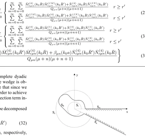
Fig. 3. x-y cross section of an irregularly shaped object placed at the edge of a wedge.
(33)
where is the dyadic Green’s function of the wedge given in (30) and is the volumetric current distribution confined to . The total field can be represented as
(34) where is the scattered field due to presence of the impedance scatterer.
Cross section of the geometry on the x-y plane is given in Fig. 3 where the origin is defined inside the scatterer. Surface of the scatterer is denoted as and two imaginary surfaces of inscribing and circumscribing segment spheres are depicted which are denoted as and , respectively.
Applying the Green’s second identity for and , one could obtain
(35) where consists of , and . It can be seen that, in the exterior region, (35) gives the scattered field in terms of the
sur-856 IEEE TRANSACTIONS ON ANTENNAS AND PROPAGATION, VOL. 62, NO. 2, FEBRUARY 2014
face integrals, and in the interior region fields expressed by the surface integrals are canceled out by the incident field. Due to the boundary condition on the surface of the wedge, integration on will vanish. Integration on will also result in zero be-cause of the plane wave behavior of the fields in the far-field. Hence the integration will be evaluated just on the surface of the scatterer.
For the field points inside the inscribed sphere , incident field can be written as
(36) where
(37) and is the compact index representing and . Since the field should be regular at the origin, spherical Bessel functions de-noted by superscript (1) are used. Scattered field outside the cir-cumscribing sphere, , is defined as
(38) in which Hankel functions, denoted by superscript (4), are chosen to satisfy the radiation condition.
If we consider on which is a segment sphere centered at the origin totally inside the scatterer, and on , coefficients of the incident field and the surface field on can be related. We can expand the electric field on the surface of the scatterer as follows:
(39) where the regular functions are chosen due to the continuity of the fields. On the surface of the scatterer, impedance boundary condition is applied
(40) Using (35) and the orthogonality of the vector wave functions over the inscribing sphere, one could obtain the following ma-trix relation: (41) where (42) (43) (44) (45) and (46) (47) To establish the relation between the surface fields on and the scattered field, we consider is on which is a segment sphere centered at the origin totally outside of the scatterer, and on . Again using (35) and (40) and orthogonality of vector wave functions over circumscribing sphere, we can obtain the following matrix relation between the unknown coefficients of the scattered field and the surface fields
(48) where (49) (50) (51) (52)
Using (41) and (48), we can relate the scattered field coefficients to the incident field coefficients in matrix form as
(53) where the T-matrix is defined as
(54) Equation (53) shows the relation between the scattered field coefficients and the incident field coefficients which can be cal-culated using (33) and (36) as
(55) (56)
In addition to the size of the scatterer, convergence of the T-matrix depends on the choice of the origin of coordinates and the ratio of the radii of circumscribing and inscribing spheres
which is discussed in [18]. For elongated bodies, as ratio of the radii of circumscribing and inscribing spheres increase, trunca-tion size increases.
V. NUMERICALRESULTS
We analytically verify T-matrix method by employing it for a spherical impedance boss centered at the edge. Then, results are compared with the one obtained from the dyadic Green’s func-tion solufunc-tion. To this aim, a spherical scatterer centered at the origin with radius is considered. Since the surface is spherical, orthogonality of auxiliary vector wave functions can be utilized. For this geometry, Q-matrix elements are calculated as
(57) (58) (59)
(60) and for is found to be
(61) (62) (63)
(64) It is seen that both and are diagonal matrices, conse-quently, according to (54), T-matrix is diagonal too. Substituting these elements in (53) and performing the matrix operations we obtain
(65) (66) Coefficients relating to in (65) are identical to
which is given in (15). Similarly, coefficients in (66) are same
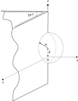
Fig. 4. Geometry of the spherical boss on the edge where the origin of coordi-nates is shifted by away from the center of the spherical boss.
as defined in (16). Scattered field coefficients can be found by substituting (55) and (56) in (65) and (66). The re-sulting scattered field is
(67) which is identical to
(68) This result indicates that the T-matrix method and the dyadic Green’s function solution are in perfect agreement for a spher-ical scatterer.
To verify the T-matrix, once more the spherical scatterer can be used but this time its center is placed at a distance from the origin. In this case there is no spherical symmetry with respect to the origin, consequently, off-diagonal components of the and are non zero. Also, the summation is truncated as
and . We compare the monostatic
scattered field obtained from T-matrix solution with the DGF solution. Since the observation and source points are in the far-field of the scatterer and also the wedge is infinitely long in the -direction, moving the origin on the -axis will just introduce a constant phase shift. As a result, two approaches must give the same result if the origin is moved away from the center of the spherical scatterer. This procedure has been proposed by Waterman to illustrate the validity of the T-matrix solution [16].
858 IEEE TRANSACTIONS ON ANTENNAS AND PROPAGATION, VOL. 62, NO. 2, FEBRUARY 2014
TABLE I
CONVERGENCE OFT-MATRIX FORSPHERICALBOSSWITH
Geometry of the problem is depicted in Fig. 4 where a spher-ical boss of radius with surface impedance
positioned on the edge of on an half-plane is considered. The origin of coordinates is shifted by
away from the center of the sphere. Source is a infinitesimal dipole positioned in the far-field of the scatterer at a fixed ele-vation angle .
Monostatic scattered field is plotted for fixed elevation angle , and is varied from 0 –360 . Note that scattered field only includes the contribution of the spherical boss only. Therefore, in the dyadic Green’s function solution only is considered. In the calculation of the and matrix elements, integrals are non zero only for , due the azimuthal symmetry of the geometry. Truncation size for and matrices are
and . Using this truncation size, maximum relative error of the T-matrix for the monostatic scattered field with respect to DGF solution is under 1%. Maximum relative error for mono-static scattering pattern is tabulated for various truncation sizes in Table I. Total computation time, using a desktop computer with Intel Core i5-2500 @ 3.3 GHz processor, is 1.88 hours and total allocated memory is 348 MB.
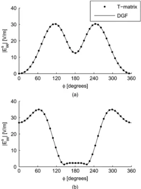
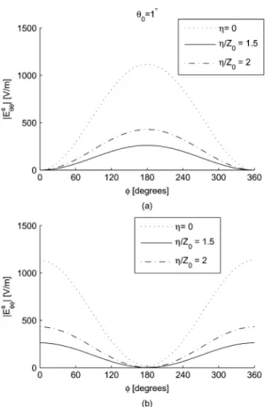
Fig. 5 shows the monostatic scattering pattern for . In this case, both source and observation points are in the paraxial
region and is the dominant mode in this
re-gion. Therefore, varies as and varies as
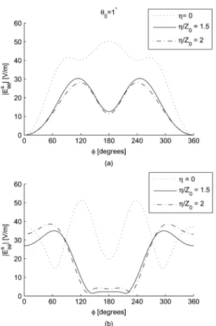
, approximately. Fig. 6 shows the mono-static scat-tering pattern for . We can observe that electric field intensity has dropped significantly compared with the paraxial case since the effect of edge guided waves diminishes as we move away from the edge. Furthermore, higher order modes are also excited.
According to Figs. 5 and 6, the T-matrix and the dyadic Green’s function solutions are in perfect agreement.
T-matrix is also applied to a prolate spheroid for which the minor axis is and the ratio of major axis to minor axis is . Impedance of the scatterer is considered as . Monostatic scattering pattern for a point source positioned in the far-field of the scatterer at elevation angle
is plotted in Fig. 7.
Table II shows the convergence of monostatic scattered field for the prolate spheroid geometry. According to Table II, rel-ative error is below 1% where the reference solution has the
truncation size of .
In order to observe the effect of the surface impedance of the scatterer, monostatic scattering pattern is plotted for a spher-ical sphere of radius with impedances of
. Note that, represents the PEC scatterer. It can
Fig. 5. Monostatic scattering pattern for the spherical boss with and at elevation angle (a) polarization (b) polarization.
Fig. 6. Monostatic scattering pattern for the spherical boss with and at elevation angle (a) polarization (b) polarization.
be observed that surface impedance of the scatterer also affects the scattered field amplitude. As the impedance mismatch be-tween the scatterer and the free space increases, the maximum value of the scattered field increases. However, scattering pat-tern also varies with respect to the impedance of the scatterer.
VI. CONCLUSION
In this work, scattering from impedance object at the edge of a perfectly conducting wedge is investigated. For the simple case of a spherical boss, dyadic Green’s function is developed. Then,
Fig. 7. Monostatic scattering pattern for the prolate spheroid with and at elevation angle (a) polarization (b) polarization.
TABLE II
CONVERGENCE OFT-MATRIX FORPROLATESPHEROID WITH
for the single irregularly shaped scatterer, T-matrix formulation was introduced. This method is applied to a spherical scatterer and the solution is compared with the dyadic Green’s function solution. Perfect agreement between two methods is achieved for two cases of a spherical scatterer at the origin and the origin shifted away from the center of the sphere. According to the obtained scattering patterns, electric field intensity is highly en-hanced due to the edge guided waves. Therefore, scattered field intensity is high in the paraxial region where source is posi-tioned close to the edge. As we move away from the paraxial region, field intensity drops significantly. In addition, scattering patterns for several surface impedance values are presented and according to this numerical results it can be concluded that as the impedance mismatch between the scatterer and the free space increases, maximum field intensity also increases.
As a future work, this solution can be asymptotically evalu-ated in order to improve higher order propagation models for
Fig. 8. Monostatic scattering pattern for the impedance spherical scatterer with radius and at elevation angle (a) polarization (b) polarization.
terrain profiles [19]–[22]. In addition, contribution of the scat-terer to the edge currents can be calculated by evaluating the scattered field in the paraxial region to be used as a benchmark solution for equivalent edge current approaches [23], [24].
APPENDIXA
SPHERICALVECTORWAVEFUNCTIONS
Solenoidal spherical vector wave functions are defined as follows:
(69)
(70) where is the radial function representing spherical Bessel and Hankel functions and and subscripts represents
the even and odd functions. and
are the auxiliary vector wave function. They are simply defined by factoring out the radial dependence
860 IEEE TRANSACTIONS ON ANTENNAS AND PROPAGATION, VOL. 62, NO. 2, FEBRUARY 2014
Fig. 9. Monostatic scattering pattern for the shifted sphere with radius and at elevation angle (a) polarization (b) polarization.
(72)
(73) (74) where is the Ferrer’s type associated Legendre function where the sum of the index and order is an integer . Hence, the function is regular when . Detailed analysis and orthogonality relations of vector wave functions are given in [10].
REFERENCES
[1] J. B. Keller, “How dark is the shadow of a round-ended screen?,” J.
Appl. Phys., vol. 30, no. 9, pp. 1452–1454, 1959.
[2] R. Kouyoumjian and W. D. Burnside, “The diffraction by a cylinder-tipped half-plane,” IEEE Trans. Antennas Propag., vol. 18, pp. 424–426, May 1970.
[3] W. Halliday, “On uniform asymptotic Green’s functions for the perfectly conducting cylinder tipped wedge,” IEEE Trans. Antennas
Propag., vol. AP-33, no. 9, pp. 1020–1025, Sep. 1985.
[4] G. Pelosi, R. Coccioli, G. Manara, and A. Monorchio, “Scattering from a wedge with cavity backed apertures in its faces and related configura-tions: Te case,” in Proceedings Microw. Antennas Propag., 1995, vol. 142, no. 2, pp. 183–188, IET.
[5] M. Calamia, R. Coccioli, G. Pelosi, and G. Manara, “A hybrid FEM/UTD analysis of the scattering from a cavity backed aperture in the face of a perfectly conducting wedge,” Compel Int. J. Computation
Math in Electrical Electronic Eng., vol. 13, pp. 229–236, 1994.
[6] A. Borgioli, R. Coccioli, G. Pelosi, and J. L. Volakis, “Electromagnetic scattering from a corrugated wedge,” IEEE Trans. Antennas Propag., vol. 45, no. 8, pp. 1265–1268, Aug. 1997.
[7] J. J. Kim, H. J. Eom, and K. C. Hwang, “Electromagnetic scattering from a slotted conducting wedge,” IEEE Trans. Antennas Propag., vol. 58, no. 1, pp. 222–226, 2010.
[8] M. Christou and A. Polycarpou, “Analysis and design of longitudinally corrugated cylindrical tips for reduced diffraction in the shadow region of a conducting wedge,” IET Microwaves, Antennas Propag., vol. 5, no. 15, pp. 1857–1862, 2011.
[9] W.-S. Lee, S.-J. Lee, D.-J. Lee, W.-S. Lee, and J.-W. Yu, “Te scattering from concaved wedges with longitudinal corrugations,” IEEE Trans.
Antennas Propag., vol. 61, no. 4, Apr. 2013.
[10] O. M. Buyukdura, S. D. Goad, and R. G. Kouoyoumjian, “A spherical wave representation of the dyadic Green’s function for a wedge,” IEEE
Trans. Antennas Propag., vol. 44, no. 1, pp. 12–22, 1996.
[11] G. Franceschetti, A. Iodice, A. Natale, and D. Riccio, “Stochastic theory of edge diffraction,” IEEE Trans. Antennas Propag., vol. 56, no. 2, Feb. 2008.
[12] M. Albani, “’Stochastic theory of edge diffraction’: An alternative for-mulation,” IEEE Trans. Antennas Propag., vol. 57, no. 8, Aug. 2009. [13] J. L. Volakis and T. B. A. Senior, Approximate Boundary Conditions
in Electromagnetics. London, U.K.: The Institution of Electrical
En-gineers, 1995.
[14] J. Meixner, “The behavior of electromagnetic fields at edges,” IEEE
Trans. Antennas Propag., vol. AP-20, no. 4, pp. 442–446, Jul. 1972.
[15] P. H. Pathak, “On the eigenfunction expansion of electromagnetic dyadic Green’s functions,” IEEE Trans. Antennas Propag., vol. AP-31, no. 6, pp. 837–846, Nov. 1983.
[16] P. C. Waterman, “Matrix formulation of electromagnetic scattering,”
Proc. IEEE, vol. 53, no. 8, pp. 805–810, Aug. 1965.
[17] P. C. Waterman, “Symmetry, unitarity, and geometry in electromag-netic scattering,” Phys. Rev. D, vol. 3, no. 4, pp. 825–839, Feb. 1971. [18] P. C. Waterman, “Survey of T-matrix methods and surface field
repre-sentations,” Acoust., Electromagn. Elastic Wave Scatter.-Focus
T-Ma-trix Approach, vol. 1, pp. 61–78, 1980.
[19] C. A. Tunc, A. Altintas, and V. B. Erturk, “Examination of existent propagation models over large inhomogeneous terrain profiles using fast integral equation solution,” IEEE Trans. Antennas Propag., vol. 53, no. 9, pp. 3080–3083, 2005.
[20] A. Yagbasan, C. A. Tunc, V. B. Erturk, A. Altintas, and R. Mittra, “Characteristic basis function method for solving electromagnetic scat-tering problems over rough terrain profiles,” IEEE Trans. Antennas
Propag., vol. 58, no. 5, pp. 1579–1589, 2010.
[21] D. A. Kapp and G. S. Brown, “A new numerical method for rough-surface scattering calculations,” IEEE Trans. Antennas Propag., vol. 44, no. 5, p. 711, 1996.
[22] D. Colak, R. Burkholder, and E. Newman, “Multiple sweep method of moments analysis of electromagnetic scattering from 3D targets on ocean-like rough surfaces,” Microw. Opt. Technol. Lett., vol. 49, no. 1, pp. 241–247, 2007.
[23] P. Lu and M. Ando, “Full pattern comparision of PO and MER line integrations with SGO correction,” in Proc. Antennas Propag. Soc. Int.
Symp., Chicago, IL, USA, Jul. 2012, pp. 1–2.
[24] A. Altintas and P. Russer, “Time-domain equivalent edge currents for transient scattering,” IEEE Trans. Antennas Propag., vol. 49, no. 4, pp. 602–606, 2001.
Behnam Ghassemiparvin was born on May 21, 1987, in Tabriz, Iran. He received the B.S. degree in electrical engineering-telecommunication from University of Tabriz, Tabriz, Iran, in 2010 and the M.S. degree in electrical and electronics engineering from Bilkent University, Ankara, Turkey, in 2012, where he is currently pursuing the Ph.D. degree.
Ayhan Altintas (SM’93) received the B.S. and M.S. degrees from Middle East Technical University, Ankara, Turkey and the Ph.D. degree from Ohio State University, Columbus, OH, USA, in 1979, 1981, and 1986, respectively, all in electrical engi-neering.
Currently, he is a Professor at Bilkent University, Ankara, Turkey. He is also the Director of Commu-nication and Spectrum Management Research Center (ISYAM). His research interests are in electromag-netics, antennas, propagation, and wireless commu-nication systems.
Dr. Altintas is a member of Sigma Xi and Phi Kappa Phi and a recipient of IEEE Third Millennium Medal. He is a Fulbright Scholar and an Alexander von Humboldt Fellow. He received the Ohio State University ElectroScience Laboratory Outstanding Dissertation Award of 1986, IEEE 1991 Outstanding Student Branch Counselor Award, 1991 Research Award of the Prof. Mustafa N. Parlar Foundation of METU, and Young Scientist Award of Scientific and Technical Research Council of Turkey (Tubitak) in 1996. He was the Chairman of IEEE Turkey Section for the terms 1991–1993 and 1995–1997. He is the Founder and First Chair of the IEEE AP/MTT Chapter in the Turkey Section. At present, he is the President of the National Committee of URSI-Turkey.