Research Article
A Miniaturized Patch Antenna by Using a CSRR Loading Plane
Mehrab Ramzan
1and Kagan Topalli
21Department of Electrical and Electronics Engineering, Bilkent University, 06800 Ankara, Turkey 2National Nanotechnology Research Center (UNAM), Bilkent University, 06800 Ankara, Turkey
Correspondence should be addressed to Kagan Topalli; [email protected] Received 15 June 2015; Revised 16 July 2015; Accepted 26 July 2015
Academic Editor: Maria E. De Cos
Copyright © 2015 M. Ramzan and K. Topalli. This is an open access article distributed under the Creative Commons Attribution License, which permits unrestricted use, distribution, and reproduction in any medium, provided the original work is properly cited.
This paper presents a design methodology for the implementation of a miniaturized square patch antenna and its circuit model for 5.15 GHz ISM band. The miniaturization is achieved by employing concentric complementary split ring resonator (CSRR) structures in between the patch and ground plane. The results are compared with the traditional square patch antenna in terms of area, bandwidth, and efficiency. The area is reduced with a ratio of 1/4 with respect to the traditional patch. The miniaturized square patch antenna has an efficiency, bandwidth, and reflection coefficient of 78%, 0.4%, and−16 dB, respectively. The measurement and circuit modeling results show a good agreement with the full-wave electromagnetic simulations.
1. Introduction
Microstrip patch antennas are preferred due to their low cost, light weight, and ease of integration in many microwave applications. However, there is demand on the reduction of antenna size in particular applications such as some military and commercial wireless communication systems where the system size and profile are a constraint. Over the past few years, significant amount of work has been done to reduce the size of the patch antennas. One of the traditional methods is to use materials with high permittivity [1] which yields a size reduction up to 30–50%. However high permittivity substrates lead to high cost and suffer from surface waves which degrade the radiation characteristics of the antenna by increasing significant amount of side lobes [2–4]. To suppress the surface waves a number of techniques are proposed in [5–
7]. Among them, the most famous remedy is to surround the antenna structure with band gap structures to prevent energy from being trapped inside the substrate. However, forming a band gap by making periodically placed holes occupies a large area making this approach impractical for miniaturized antennas. Another technique to reduce the patch size is to employ RIS (reactive impedance substrate) as discussed in [8] where Trans-Tech MCT-25 magnesium calcium titanate composition (𝜀𝑟 = 25) is used as a RIS substrate. However
using such a high permittivity and nonstandard substrate increases the cost significantly.
In some other research efforts, it is proposed to achieve miniaturization by increasing the path of the current on the patch antenna. It is reported in [9] that a reduction up to 36% is achieved by using slits. Some of the most common methods which can be employed to reduce the size of the antenna are inserting slots [9], shorting pin [10], corrugation structure [11], and iris structures [12]. However, all of these methods have some limitations such as low performance and manufacturing complexity.
In order to reduce the size of patch antennas comple-mentary split ring resonators (CSRRs) on ground plane [13–
15] are proposed typically providing average reduction of about 30% in area which is accompanied with a decrease of front to back ratio up to 1 dB. They also increase the cross-polarization to the same level as the cocross-polarization. In this paper, miniaturized square patch antenna is proposed for ISM 5.15 GHz band by using a simple design methodology. The size reduction is achieved by employing a CSRR based metamaterial plane in between the patch and ground plane without degrading the front to back ratio significantly. The measurement results indicate that the area is reduced with a ratio of 1/4 compared to a traditional patch at the expense of an acceptable degradation in efficiency and bandwidth.
Volume 2015, Article ID 495629, 9 pages http://dx.doi.org/10.1155/2015/495629
Ground plane CSRR Square patch Feed line Y X Z Su bs_ 1 Su bs_ 2
Figure 1: 3D side view of miniaturized antenna consisting of CSRR (metamaterial) layer between the square patch and ground plane.
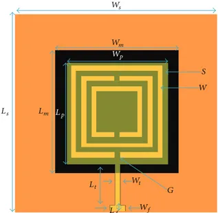
S W G Ws Wm Wp Lt Lm Lp Ls Lf Wt Wf
Figure 2: Top view of miniaturized antenna with physical parame-ters.
To the authors’ knowledge the approach presented in this work, which is also supported with measurements and circuit model, is applied on square patches for the first time. The following sections present the antenna design approach and simulation results in comparison with the measurement results and finally a simple transmission line model of miniaturized patch is discussed.
2. Antenna Design
The miniaturized patch antenna consists of two separate substrates where the metamaterial plane is sandwiched in between, as shown inFigure 1. The top and bottom planes on the surfaces of this stack of substrates form the patch antenna and the ground plane, respectively. Rogers RT/Duroid 6002 having relative permittivity of 𝜀𝑟 = 2.92, loss tangent of tan𝛿 = 0.002, and height of ℎ = 0.762 mm is used for the design. The top view of the miniaturized antenna geometry is shown in Figure 2. The metamaterial plane is composed of a metal plane with CSRR pattern on it. Three concentric CSRRs are fit considering the fabrication tolerances. Two RT/Duroid 6002 with 0.762 mm heights are used and denoted as subs 1 and subs 2 inFigure 2. Considering the analysis and
Table 1: Physical parameters of the traditional antenna with quarter-wave transformer and miniaturized patch antennas.
Parameters Traditional patch(mm) Miniaturized patch (mm)
𝐿𝑠 40 28 𝑊𝑠 40 28 𝐿𝑝 15.95 8 𝑊𝑝 15.95 8 𝐿𝑡 9 14.4 𝑊𝑡 0.7 1.2 𝐿𝑓 4 1 𝑊𝑓 4 4 𝐿𝑚 — 14.4 𝑊𝑚 — 14.4 𝑆 — 0.51 𝐺 — 0.3 𝑊 — 0.25
the proposed models of SRR structure discussed in [14,16–
18], the gap𝐺 of the SRR acts as a capacitor and length of the SRR increases the inductive effects. CSRR is the dual structure of SRR. The metamaterial plane in between two substrates acts as the loading element decreasing the electrical size of the antenna. In order to assess the level of miniaturization, a square shaped traditional patch is also implemented without the metamaterial plane.
3. Results and Discussion
The optimization of antennas is carried out by using para-metric analyses of Ansys HFSS. A traditional patch, where the metamaterial plane is not included in between two substrates, is chosen as the reference antenna.Table 1gives the physical parameters of the antennas. The miniaturized antennas are implemented by attaching two separate substrates: The first one, subs 1, has the patch pattern and the second one,
subs 2, has the CSRR (metamaterial layer) pattern on the
top surface and the ground plane at the bottom. LPKF rapid PCB prototyping tool [19] is used to pattern the layers with a precision of about 0.2 mm. The substrates are aligned by using thru holes and separate substrates are fixed using Kapton tapes as shown inFigure 3.Figure 4shows the measured and simulated reflection coefficients of the traditional patch and miniaturized patch which has an area of 1/4 of the traditional
SMA connector Feed line
Traditional square patch
Feed line SMA connector Thru hole Thru hole Kapton tape QWT Miniaturized square patch
Figure 3: A photograph of the fabricated designs of traditional patch with quarter-wave transformer and miniaturized patch with longer feed line. 4.5 5 5.5 5.8 0 Frequency (GHz) T. P. designed T. P. measured M. P. designed M. P. measured −5 −10 −15 −20 −25 |S11 |(dB)
Figure 4: Measured and simulated reflection coefficient comparison of traditional antenna with quarter-wave transformer and miniatur-ized antenna with longer feed line.
patch. It is evident from the results that the miniaturization has led to the reduction of the −10 dB bandwidth of the antenna from 2% to 0.4%. The measurement results also indicate that there is a shift between the measured and simulated results of both antennas. The main reason behind this shift is the unwanted air gap remaining in between the substrates during the prototyping process. In order to verify the effect of the air gap on the resonant frequency, the simulation models are modified by including the air gap in between subs 1 and subs 2.Figure 5compares the results of measured and modified simulations for the reflection coefficients. A perfect agreement is achieved by employing an air gap of 0.11 mm and 0.045 mm in between subs 1 and subs 2 of traditional antenna and miniaturized patch, respectively. It should be noted here that miniaturized antenna is quite sensitive to air gap since the characteristics of the CSRR region are strongly affected by the presence of air. Since only miniaturized patch incorporates CSRR layer, which increases
Frequency (GHz) T. P. shifted T. P. measured M. P. shifted M. P. measured 4.75 4.95 5.15 5.35 5.55 5.75 0 −5 −10 −15 −20 −25 |S11 |(dB)
Figure 5: Measured and shifted simulated reflection coefficient comparison of the traditional antenna with quarter-wave trans-former and miniaturized antenna with longer feed line.
60 120 30 150 0 180 30 150 60 120 90 90 T. P. designed T. P. measured 0 10 −10 −20
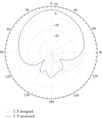
Figure 6: Simulation and measurement results for𝐸-plane gain of traditional patch with quarter-wave transformer (frequency: 5.38 GHz).
its sensitivity to the air gap, that is why the measured reflec-tion coefficient of miniaturized patch has moved to higher frequency as compared to the traditional patch antenna as shown inFigure 5. Figures6and7show the simulated and measured gain patterns of traditional patch in 𝐸- and 𝐻-planes, respectively. The measurements are carried out using Satimo StarLab 18 GHz antenna measurement system. The simulated and measured results agree well verifying that the manufacturing method of stacking multiple substrates can
60 120 30 150 0 180 30 150 60 120 90 90 T. P. designed T. P. measured 0 10 −10 −20
Figure 7: Simulation and measurement results for𝐻-plane gain of traditional patch with quarter-wave transformer (frequency: 5.38 GHz).
work effectively for the traditional patch. Figures 8 and 9
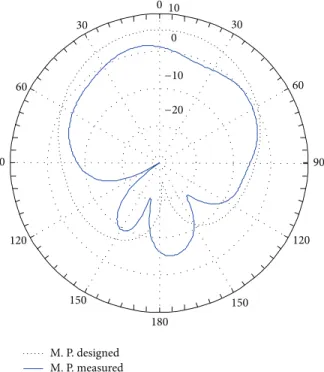
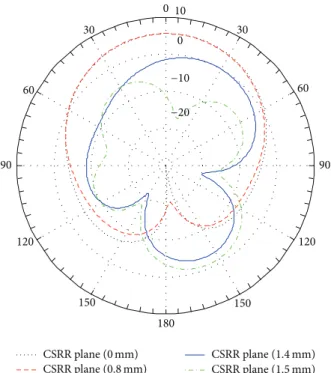
present the simulated and measured gain patterns in𝐸- and 𝐻-plane of miniaturized patch. There is a slight decrease observed in the gain of miniaturized patch which is due to a slight displacement of metamaterial layer along the feed line during the fabrication.Figure 10shows the change of the antenna gain as the metamaterial layer is shifted towards the feed. It is noted that displacement of even less than 1 mm from the patch center towards the feed line reduces the gain tremendously. As the CSRR layer position determines the current distribution on the miniaturized patch, the radiation patterns being highly dependent on surface current distribution will also change. The detailed discussion on the change of current distribution with respect to CSRR layer is given in the following sections of paper. Figures11and12show how the gain patterns are distorted if CSRR layer is not placed accurately beneath the miniaturized patch. The manufacturing accuracy can be improved by using photolithographic and wafer bonding processes, where double sided patterning and bonding is achievable on low-loss substrate with alignment accuracy in the order of a few micrometers. After miniaturization the front to back ratio is reduced from 23 dB to 21.5 dB. The co- to cross-polarization ratio of traditional patch in𝐸- and 𝐻-plane are 47 and 30 dB, respectively. For miniaturization of patch antenna the co- to cross-polarization ratio in𝐸- and 𝐻-plane are reduced to 43 and 27 dB, respectively. With this level of miniaturization the miniaturized values of front to back ratio and co- to cross-polarization ratio are practically acceptable and comparable to the results given in [7,20,21].
60 120 30 150 0 180 30 150 60 120 90 90 M. P. designed M. P. measured 0 10 −10 −20
Figure 8: Simulation and measurement results for𝐸-plane gain of miniaturized patch with longer feed line (frequency: 5.51 GHz).
60 120 30 150 0 180 30 150 60 120 90 90 M. P. designed M. P. measured 0 10 −10 −20
Figure 9: Simulation and measurement results for𝐻-plane gain of miniaturized patch with longer feed line (frequency: 5.51 GHz).
Table 2gives a summary of the performances of the
tradi-tional patch and miniature antennas. The miniaturization of the patch is achieved at the expense of acceptable degradation in gain, efficiency, and bandwidth.
0 0.2 0.4 0.6 0.8 1 1.2 1.4 0 2 4 6 Ga in (dB i) CSRR layer displacement (mm) −2 −4 −6
Figure 10: The simulation results showing the variation of the antenna gain due to the displacement (misalignment) of the CSRR layer along the feed line.
60 120 30 150 0 180 30 150 60 120 90 90 CSRR plane (1.5 mm) CSRR plane (1.4 mm) CSRR plane (0.8 mm) CSRR plane (0 mm) 0 10 −10 −20
Figure 11: Simulation results for𝐸-plane gain of miniaturized patch at different location of CSRR plane moved towards the feed line.
4. Modeling of Miniaturized Patch
Loaded with CSRR Layer
In order to assess the operating principle and define a guide-line to design a miniaturized antenna, first a transmission line loaded with CSRR plane shown inFigure 13is simulated. The circuit model given inFigure 14is employed to verify the operation of CSRR plane [22]. Figures 15and 16 show the reflection and transmission coefficient results where a good agreement is noted between the simulations and model.
60 120 30 150 0 180 30 150 60 120 90 90 CSRR plane (1.5 mm) CSRR plane (1.4 mm) CSRR plane (0.8 mm) CSRR plane (0 mm) 0 10 −10 −20
Figure 12: Simulation results for𝐻-plane gain of miniaturized patch at different location of CSRR plane moved towards the feed line.
Port 1 Port 2 Transmission line Ground CSRR
Figure 13: Transmission line loaded with CSRR. Table 2: Comparison of performances of the traditional and miniaturized patch antennas obtained through simulations.
Traditional patch Miniaturized patch
Gain (dBi) 7.35 5.72
Directivity (dBi) 7.39 6.78
Rad. efficiency (%) 98.6 78
Bandwidth (%) 2 0.4
Bandwidth (10 dB) (MHz) 103.4 21.2
Prior to modeling of miniaturized square patch, the traditional patch is modeled using transmission line model of patch as shown inFigure 17where the two radiating slots along the length of patch are modeled as shunt reactances. Figures 18 and 19 compare the magnitude and phase of reflection coefficient of circuit model and simulated results, respectively. The model results show a very good agreement with the simulated results.
Similar to the traditional patch antenna, the miniatur-ized one is also modeled with two radiating slots loaded with CSRR as shown inFigure 20. It is sufficient to model
Zo
CCSRR1 CCSRR2 CCSRR3 CCSRR4
LCSRR1 LCSRR2 LCSRR3 LCSRR4
Zo
Figure 14: Circuit model of a transmission line loaded with CSRR.
4.5 5 5.5 5.8 0 Frequency (GHz) Circuit model Simulation −60 −40 −20 |S11 |(dB)
Figure 15: Comparison of circuit model and simulated reflection coefficient results of transmission line loaded with CSRR.
Table 3: Circuit modeling parameters of traditional patch and miniaturized patch antenna.
Miniaturized patch circuit model parameters
Traditional patch circuit model parameters 𝑍𝑜(Ω) 40 𝑍𝑜(Ω) 40 𝑙𝑜(mm) 1 𝑙𝑜(mm) 4 𝑍𝑜𝑡𝑚(Ω) 90 𝑍𝑜𝑡(Ω) 106 𝑙𝑜𝑡𝑚(mm) 14.4 𝑙𝑜𝑡(mm) 9 𝑍𝑜𝑚(Ω) 3.97 𝑍𝑜𝑝(Ω) 17.5 𝑙𝑜𝑚(mm) 8 𝑙𝑜𝑝(mm) 15.95 𝑅𝑝𝑚(Ω) 500 𝑅𝑝(Ω) 915 𝐶𝑝𝑚(pF) 9.8 𝐶𝑝(pF) 0.44 𝐶CSRR(pF) 16.7 — — 𝐿CSRR(pH) 57 — —
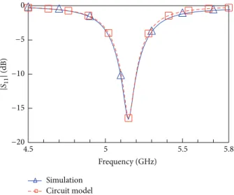
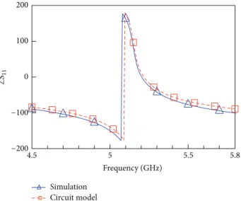
the CSRR in miniaturized patch with a single 𝐿𝐶 section whose resonant frequency lies in the regime of resonant frequency of the antenna. Table 3 shows the summary of modeling parameters of traditional and miniaturized patch antennas. Figures 21 and 22 compare the magnitude and phase of reflection coefficient of model and simulated results, respectively. The miniaturized patch model results agree well
Frequency (GHz) Circuit model Simulation 4.5 5 5.5 5.8 0 −30 −20 −10 |S21 |(dB)
Figure 16: Comparison of circuit model and simulated transmission coefficient results of transmission line loaded with CSRR.
Zo Zot Zop
lot
lo lop
Rp Cp Rp Cp
Figure 17: Circuit model of traditional patch antenna using trans-mission lines. Frequency (GHz) 4.5 5 5.5 5.8 0 −20 −15 −10 −5 |S11 |(dB) Circuit model Simulation
Figure 18: Comparison of circuit model and simulated reflection coefficient results of traditional patch antenna.
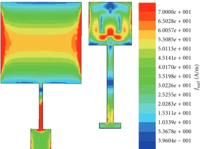
with the simulation results.Figure 23shows the surface cur-rent,𝐽𝑠, distribution on traditional square patch and minia-turized patch. The CSRR is changing the current distribution on the miniaturized patch which, in turn, changes the input impedance of the miniaturized patch. It also explains the reason behind the miniaturization of the square. The CSRR plane causes the current on the square patch to follow a longer
Frequency (GHz) 4.5 5 5.5 5.8 0 100 200 −200 −100 ∠S11 Circuit model Simulation
Figure 19: Comparison of circuit model and simulated phase of reflection coefficient results of traditional patch antenna.
Zo Zotm Zom lo lotm lom Rpm Rpm Cpm Cpm CCSRR/2 CCSRR/2 2LCSRR 2LCSRR
Figure 20: Circuit model of miniaturized patch loaded with CSRR using transmission lines.
Frequency (GHz) 4.5 5 5.5 5.8 0 −30 −25 −20 −15 −10 −5 |S11 |(dB) Circuit model Simulation
Figure 21: Comparison of circuit model and simulated reflection coefficient results of miniaturized patch antenna loaded with CSRR.
path allowing miniaturization. The current distribution also explains the degradation of the gain of the miniaturized antenna with the slight change of the CSRR plane location since the current distribution on the miniaturized antenna is highly dependent on the location of CSRR as shown in
Figure 23. It should be noted that if the location of the CSRR
Frequency (GHz) 4.5 5 5.5 5.8 0 100 200 −100 −200 ∠S11 Circuit model Simulation
Figure 22: Comparison of circuit model and simulated phase of reflection coefficient results of miniaturized patch antenna loaded with CSRR.
is changed, it modifies the current distribution on antenna which eventually affects the far field radiation and gain of the antenna.Figure 24shows current distribution on different locations of CSRR plane shifted towards the feed line of miniaturized antenna. The current distribution is highly dependent on the location of CSRR. As the CSRR plane is moved towards feed line, it starts loading the feed line. After 1 mm of shift, it is deduced that the maximum current distribution is being concentrated around CSRR towards the feed line which, in turn, affects the gain and radiated power of the antenna. Furthermore, as the current distribution on patch changes, the input impedance of patch starts to change. For a shifted CSRR plane, we need a slight modification in the matching network. However, our matching is fixed and designed for a CSRR positioned with reference to the center of the patch.
5. Conclusion
This paper presents simple yet effective method for the miniaturization and modeling of the patch antennas. Minia-turization of the square patch antenna is achieved by employ-ing a horizontal layer of CSRR in between the patch and ground plane. The measurements results of the miniaturized antennas indicate that CSRR based loading plane shrinks the antenna area to 1/4 of a traditional patch without sacrificing the antenna performances significantly. It is also demonstrated that the CSRR loaded antenna is very sensitive to the air gap in between the two substrates indicating that the antenna can be reconfigured using reactive loading elements on this plane.
Conflict of Interests
The authors declare that there is no conflict of interests regarding the publication of this paper.
7.0000e + 001 6.5028e + 001 6.0057e + 001 5.5085e + 001 5.0113e + 001 4.5141e + 001 4.0170e + 001 3.5198e + 001 3.0226e + 001 2.5255e + 001 2.0283e + 001 1.5311e + 001 1.0339e + 001 5.3678e + 000 3.9604e − 001 Jsurf (A/m)
Figure 23: Comparison of surface current(𝐽𝑠) distribution of traditional patch and miniaturized patch loaded with CSRR.
0 mm 0.5 mm 0.8 mm 1.2 mm 1.5 mm
Figure 24: Current distribution on the miniaturized patch antenna on different location of CSRR layer.
Acknowledgments
The authors would like to thank Dr. Volkan Akan, Suleyman Kose, Ilhan Bayramoglu, and Dr. Evren Ekmekci for the fabrication, the measurement of the antennas, and fruitful discussions.
References
[1] D. M. Pozar and D. H. Schaubert, Microstrip Antennas, John Wiley & Sons, 1995.
[2] R. Waterhouse, “Small microstrip patch antenna,” Electronics Letters, vol. 31, no. 8, pp. 604–605, 1995.
[3] Y. Lee, S. Tse, Y. Hao, and C. G. Parini, “A compact microstrip antenna with improved bandwidth using complementary split-ring resonator (CSRR) loading,” in Proceedings of the IEEE
Antennas and Propagation Society International Symposium, pp. 5431–5434, IEEE, Honolulu, Hawaii, USA, June 2007.
[4] R. k. Baee, G. Dadashzadeh, and F. G. Kharakhili, “Using of CSRR and its equivalent circuit model in size reduction of microstrip antenna,” in Proceedings of the Asia-Pacific Microwave Conference (APMC ’07), pp. 1–4, IEEE, Bangkok, Thailand, December 2007.
[5] S. Lee, J. Woo, M. Ryu, and H. Shin, “Corrugated circular micro-strip patch antennas for miniaturization,” Electronics Letters, vol. 38, no. 6, pp. 262–263, 2003.
[6] L. K. Wong and J. Y. Wu, “Single-feed small circularly polarised square microstrip antenna,” Electronics Letters, vol. 33, no. 22, pp. 1833–1834, 1997.
[7] R. O. Ouedraogo, E. J. Rothwell, A. R. Diaz, K. Fuchi, and A. Temme, “Miniaturization of patch antennas using a
metamaterial-Inspired technique,” IEEE Transactions on Anten-nas and Propagation, vol. 60, no. 5, pp. 2175–2182, 2012. [8] H. Mosallaei and K. Sarabandi, “Antenna miniaturization and
bandwidth enhancement using a reactive Impedance substrate,” IEEE Transactions on Antennas and Propagation, vol. 52, no. 9, pp. 2403–2414, 2004.
[9] Y. Dong, H. Toyao, and T. Itoh, “Design and characterization of miniaturized patch antennas loaded with complementary split-ring resonators,” IEEE Transactions on Antennas and Propagation, vol. 60, no. 2, pp. 772–785, 2012.
[10] X. Zhao, Y. Lee, and J. Choi, “Design of a compact patch antenna using split-ring resonator embedded substrate,” Microwave and Optical Technology Letters, vol. 53, no. 12, pp. 2786–2790, 2011. [11] Y. Lee and Y. Hao, “Characterization of microstrip patch
antennas on metamaterial substrates loaded with complemen-tary split-ring resonators,” Microwave and Optical Technology Letters, vol. 50, no. 8, pp. 2131–2135, 2008.
[12] S. Islam and M. Latrach, “Design construction and testing compact size patch antenna for RFID applications,” Microwave and Optical Technology Letters, vol. 55, no. 12, pp. 2920–2925, 2013.
[13] A. Suntives and R. Abhari, “Miniaturization and isolation improvement of a multiple-patch antenna system using electro-magnetic bandgap structures,” Microwave and Optical Technol-ogy Letters, vol. 55, no. 7, pp. 1609–1612, 2013.
[14] Y.-J. Park, A. Herschlein, and W. Wiesbeck, “A photonic bandgap (PBG) structure for guiding and suppressing surface waves in millimeter-wave antennas,” IEEE Transactions on Microwave Theory and Techniques, vol. 49, no. 10, pp. 1854–1859, 2001.
[15] J. Colburn and Y. Rahmat-Samii, “Patch antennas on externally perforated high dielectric constant substrates,” IEEE Transac-tions on Antennas and Propagation, vol. 47, no. 12, pp. 1785–1794. [16] J. Baena, J. Bonache, F. Martin et al., “Equivalent-circuit models for ring resonators and complementary split-ring resonators coupled to planar transmission lines,” IEEE Transactions on Microwave Theory and Techniques, vol. 53, no. 4, pp. 1451–1461, 2005.
[17] J. Bonache, M. Gil, I. Gil, J. Garcia-Garcia, and F. Martin, “On the electrical characteristics of complementary metamaterial resonators,” IEEE Microwave and Wireless Components Letters, vol. 16, no. 10, pp. 543–545, 2006.
[18] M. S. Alam, N. Misran, B. Yatim, and M. T. Islam, “Development of electromagnetic band gap structures in the perspective of microstrip antenna design,” International Journal of Antennas and Propagation, vol. 2013, Article ID 507158, 22 pages, 2013. [19] http://www.lpkfusa.com/.
[20] S. Shi, W. Che, W. Yang, and Q. Xue, “Miniaturized patch antennas with enhanced bandwidth based on signal-inteference feed,” IEEE Antennas and Wireless Propagation Letters, vol. 14, pp. 281–284, 2015.
[21] J. Tang, R. O. Ouedraogoand, A. R. Diaz, and K. Fuchi, “A continuously tunable miniaturized patch antenna,” IEEE Transactions on Antennas and Propagation, vol. 13, pp. 1080– 1083, 2014.
[22] A. Mehdipour, T. A. Denidni, and A. Sebak, “Multi-band miniaturized antenna loaded by ZOR and CSRR metamaterial structures with monopolar radiation pattern,” IEEE Transac-tions on Antennas and Propagation, vol. 62, no. 2, pp. 555–562, 2014.
International Journal of
Aerospace
Engineering
Hindawi Publishing Corporation
http://www.hindawi.com Volume 2014
Robotics
Journal ofHindawi Publishing Corporation
http://www.hindawi.com Volume 2014
Hindawi Publishing Corporation
http://www.hindawi.com Volume 2014 Active and Passive Electronic Components
Control Science and Engineering
Journal of
Hindawi Publishing Corporation
http://www.hindawi.com Volume 2014 Machinery
Hindawi Publishing Corporation
http://www.hindawi.com Volume 2014
Hindawi Publishing Corporation http://www.hindawi.com
Journal of
Engineering
Volume 2014
Submit your manuscripts at
http://www.hindawi.com
VLSI Design
Hindawi Publishing Corporation
http://www.hindawi.com Volume 2014
Hindawi Publishing Corporation
http://www.hindawi.com Volume 2014
Shock and Vibration
Hindawi Publishing Corporation
http://www.hindawi.com Volume 2014
Civil Engineering
Advances inAcoustics and VibrationAdvances in Hindawi Publishing Corporation
http://www.hindawi.com Volume 2014 Hindawi Publishing Corporation
http://www.hindawi.com Volume 2014 Electrical and Computer Engineering
Journal of
Advances in OptoElectronics
Hindawi Publishing Corporation
http://www.hindawi.com Volume 2014
The Scientific
World Journal
Hindawi Publishing Corporation
http://www.hindawi.com Volume 2014
Sensors
Journal ofHindawi Publishing Corporation
http://www.hindawi.com Volume 2014
Modelling & Simulation in Engineering Hindawi Publishing Corporation
http://www.hindawi.com Volume 2014
Hindawi Publishing Corporation
http://www.hindawi.com Volume 2014
Chemical Engineering
International Journal of Antennas and
Propagation
International Journal of
Hindawi Publishing Corporation
http://www.hindawi.com Volume 2014
Hindawi Publishing Corporation
http://www.hindawi.com Volume 2014
Navigation and Observation
International Journal of
Hindawi Publishing Corporation
http://www.hindawi.com Volume 2014