FAKULTÄT MASCHINENBAU
Master of Science in Manufacturing TechnologyFachgebiet Werkstoffprüftechnik
Prof. Dr.-Ing. habil. Frank Walther
M a s t e r T h e s i s
The effects of grain refinement on the mechanical
properties of aluminium cast alloys used in
automotive industry
by Onur Özaydın
Registration Number: 162924
Supervisors:
Prof. Dr.–Ing. habil. Frank Walther Asisst. Prof. Dr. Mehmet İpekoğlu
Abstract
Microstructural parameters like secondary dendrite arm spacing (SDAS) strongly influence the quasistatic and, especially, fatigue properties of aluminium castings. The size of these parameters, in turn, depends on different refining elements like Ti and B. To control these microstructural parameters, the influence of grain refinement must be investigated. This study analyzes the influence of grain refinement on the mechanical properties of cast aluminium alloy (AlSi6Cu4) used in automotive industry for cylinder heads.
After literature survey, the current state of the art in the optimum percentage of refining elements has been determined and a framework for improving the mechanical properties has been developed. Refining elements have been added at different levels to check their influence on SDAS values. Microscopic analysis would be carried out to measure the SDAS values. The optimum percentage of the refining elements for the required SDAS values has been determined.
Three new refining element levels are determined and applied to related aluminium cylinder head groups. First refining element level gave 23.11 μm SDAS value which is insufficient SDAS level for the related product. Second refining element level gave 19.74 μm SDAS value which is sufficient level and it gave appropriate mechanical properties. Third refining element level gave 15.71 μm SDAS value which gave the best mechanical properties. After grain refinement, stress relief has been carried out over half of the specimens, so that the influence of post-refinement stress relief on the mechanical properties could also be investigated. The specimens have been extracted from the cylinder heads from the critical areas and they showed around 10% UTS and around 25% YS better values after stress relief. Quasistatic mechanical properties as well as fatigue properties have been investigated so that optimum percentage of Ti and B can be determined for highest ultimate tensile strength and yield strength values. Woehler curves have been generated and the resulting life has been compared with the predetermined life cycles required for the product for conformance to the performance criteria.
Acknowledgement
This study is the Master thesis of Joint Degree Master Program in Master of Science in Manufacturing Technology (MMT). The Joint Degree Master Program was carried out in cooperation between Turkish-German University and TU Dortmund University.
First, I would like to acknowledge DAAD (Deutscher Akademischer Austausch Dienst - German Academic Exchange Service) for financial support throughout my Master degree study.
Second, I would like to gratefully acknowledge to my supervisors Prof. Dr.–Ing. habil. Frank Walther from TU Dortmund and Asisst. Prof. Dr. Mehmet İpekoğlu from Turkish-German University. Their support, constructive criticism, encouragement and evaluation lead this study. In addition to this, I would like to express my appreciation to M.Sc. Shafaqat Siddique and Dipl.-Wirt.-Ing. Sebastian Myslicki for their cooperations and constructive criticisms in this thesis. Their guidances, suggestions and supports are valuable for me. At last, I would like acknowledge to Prof. Dr. Yücel Birol and Prof. Dr. Remzi Varol.
All practical works in this thesis are carried out at Cevher Aluminium Foundry in İzmir/Turkey. I am very grateful being a part of Cevher Aluminium Foundry. I would like to acknowledge to Mr. Atıf Eralp, Mr. Neşet Kiremitçi and all colleagues in Cevher Aluminium Foundry.
Finally, I would like to say my special thanks to my parents Emel Özaydın - Osman Özaydın, to my sister Sevil Özaydın Turkay, and to my dear friends Elif Şener, Mehmet Kargı and Esmeray Üstünyağız.
Table of Contents
Table of Contents i
List of Figures iii
List of Tables viii
Abbreviations and Formula Symbols x
1 Introduction 1
1.1 Objective and goals ... 1
1.2 Motivation ... 1
1.3 Outline ... 2
2 State of the Art 4
2.1 Background ... 4
2.2 Application in the automotive industry ... 12
2.2.1 Cylinder head ... 12
2.3 Foundry technology ... 15
2.3.1 Casting of aluminium cylinder heads ... 15
2.4 Material: Aluminium and aluminium alloys ... 19
2.4.1 Aluminium and aluminium alloys ... 19
2.4.2 Effect of alloying elements ... 21
2.4.3 Al-Si-Cu (3xx.x) system ... 22
2.5 Solidification ... 23
2.5.1 Solidification of Al-Si-Cu systems ... 23
2.5.2 Casting defects ... 24
2.5.3 Dendrite arm spacing (DAS) ... 27
2.6 Grain refinement ... 30
2.6.1 Mechanism of grain refinement ... 31
2.6.2 Methods of grain refinement ... 33
2.6.4 Gas content ... 34
2.7 Stress relieving ... 36
2.7.1 Stress relieving and annealing (TS condition) ... 36
3 Experimental Methods 37
3.1 Casting ... 37
3.1.1 Casting the cylinder head ... 37
3.1.2 Design of all tests ... 42
3.1.3 Casting cylinder head with different additions ... 43
3.1.4 Specimen preparation ... 45
3.1.5 Stress relieved cylinder heads ... 51
3.2 Metallurgical approach ... 51
3.2.1 Chemical composition ... 51
3.2.2 Macrostructure ... 53
3.2.3 Grain size ... 54
3.2.4 Microstructure ... 59
3.3 Brinell hardness test ... 64
3.4 SDAS measurement ... 65
3.5 Tensile test ... 66
3.6 Fatigue test ... 67
4 Results 70
4.1 Results of Brinell hardness test... 70
4.2 Results of SDAS measurement ... 71
4.3 Results of tensile test ... 79
4.4 Results of fatigue test ... 86
4.4.1 Woehler (S-N) curve ... 88
5 Discussion 92
6 Summary and Outlook 94
List of Figures
Figure 1.1: Dendritic structure [Pav10] ... 1 Figure 2.1: The effect of SDAS on UTS-YS of cast cylinder heads in 319 alloys [Zha05] ... 5 Figure 2.2: The effect of microstructure on the fatigue behaviour of 319 alloys [Zhu06] ... 8 Figure 2.3: Chronological overview of damage mechanism leading to failure [Kli12], [Rie04]
... 11 Figure 2.4: Detailed aluminium cylinder head [NN15]... 12 Figure 2.5: Cylinder head with cross-section [Bec11] ... 13 Figure 2.6: Trends in market share of casting methods for aluminium cylinder heads [NN02]
... 15 Figure 2.7: a) Top casting method, b) Bottom casting method, c) Tilt casting method [Pav08]
... 16 Figure 2.8: Filling of mould cavity in tilt gravity casting [Sme14] ... 17 Figure 2.9: a) Lading and dosing, b) Transporting of casting basin, c) Docking of casting
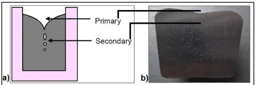
basin, d) Starting of casting, e) Ending of casting, f) Undocking of casting basin [Sme14] ... 18 Figure 2.10: a) Exogenous solidification type (1) Smooth wall, (2) Rough wall, (3) Spongy, b) Endogenous solidification type (4) Pulpy or mushy, (5) Shell forming [Bas07] ... 23 Figure 2.11: a) Higher solidification speed (Rough wall type) (x10 Magnification), b) Lower solidification speed (Spongy) (x10 Magnification) ... 24 Figure 2.12: Macrostructure pictures of gas porosity. a) x10 Magnification, b) x10 Magnification ... 25 Figure 2.13: Macrostructure pictures of gas porosity. a) x40 Magnification, b) x63 Magnification ... 25 Figure 2.14: a) Primary and secondary macro porosity [Cam94], b) Primary and secondary macro porosity... 25 Figure 2.15: Macrostructure pictures of shrinkage. a) x10 Magnification, b) x10 Magnification
... 26 Figure 2.16: a) Optical micrographs of gas porosity in cylinder head casting [Bir08], b) Optical micrographs of gas porosity in cylinder head casting ... 26
Figure 2.17: a) Optical micrographs of shrinkage in cylinder head casting [Bir08], b) Optical
micrographs of shrinkage in cylinder head casting ... 26
Figure 2.18: a) Optical micrographs of oxide in engine head casting [Kon14], b) Optical micrographs of oxide in cylinder head casting ... 27
Figure 2.19: Primary and secondary dendrite arm spacing [Dju12] ... 27
Figure 2.20: a) Microscope view sample (Magnification x100), b) SDAS measurement method (Linear interception method) ... 29
Figure 2.21: The measurement area of SDAS values on the combustion chamber [NN12] .. 30
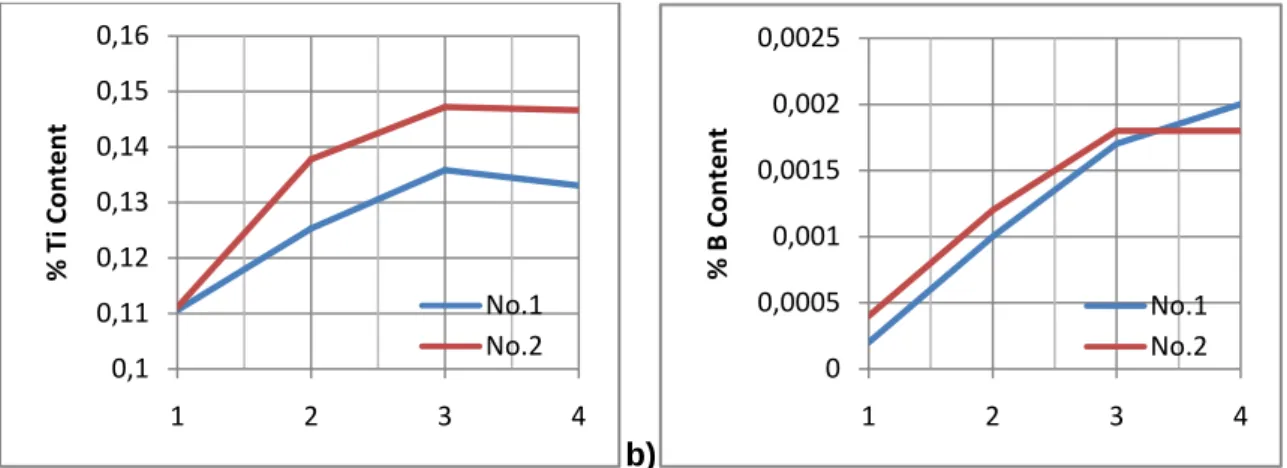
Figure 2.22: a) Ti content of grain refinement samples b) B content of grain refinement samples... 31
Figure 2.23: a) Macroscope picture of No.1.1 (Grain size: 500 µm), b) Picture of No.1.2 (Grain size: 315 µm), c) Picture of No.2.2 (Grain size: 200 µm)... 31
Figure 2.24: a) The nucleation of TiAl3 [Bac83], b) The effect of grain refiner on the cooling curve [Sig07] ... 32
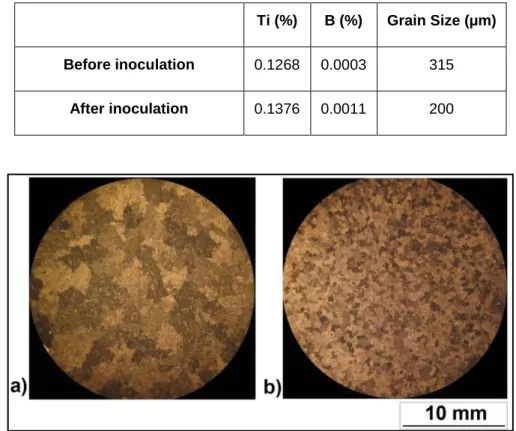
Figure 2.25: a) Macrostructure before inoculation, b) Macrostructure after inoculation ... 33
Figure 2.26: a) Weighing machine MK2200, b) Vacuum machine, c) Pressure gauge (640 mmHg) ... 35
Figure 2.27: a) Before degassing in the vacuum (Group A), b) After degassing in the vacuum (Group B) ... 36
Figure 3.1: The production line [NN15] ... 37
Figure 3.2: Transferring the liquid metal from melting furnace to transfer ladle [NN15] ... 38
Figure 3.3: a) Positions of sand cores in the mould [Sme14], b) Named sand cores [NN12] 39 Figure 3.4: Gathered sand cores in the mould [NN15] ... 39
Figure 3.5: a) Water jacket 1, b) Water jacket 2 and outlet sand core, c) Side oil channel 2, d) Side oil channel 1 and inlet sand core, e) Top sand core and oil gallery [NN12] ... 40
Figure 3.6: Solidification of cast in tilt casting process [Sme14] ... 41
Figure 3.7: Design of all measurements and tests ... 42
Figure 3.8: Temperature measurement points on the combustion chambers ... 44
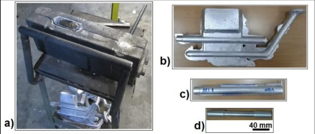
Figure 3.10: a) Tensile test bar mould, b) Uncut specimen, c) Sawed specimen, d) Machined
to d0=12 mm tensile test bar ... 46
Figure 3.11: a) CAD picture of d0=5 mm tensile test bar under the combustion chamber, b) CAD picture of d0=5 mm tensile test bar under the combustion chamber with zoom. ... 47
Figure 3.12: a) Combustion chamber and tensile test bar, b) Sawed cylinder head, c) Perspective view of critical region, d) Separated critical region, e) Machined d0=5 mm tensile test bar ... 47
Figure 3.13: Roughness test machine [NN12] ... 48
Figure 3.14: a) X-Ray inspection [NN12], b) X-Ray photograph of two d0=12 mm tensile test specimens. ... 48
Figure 3.15: a) Measured area on the first and third combustion chamber region, b) Sample for microstructure and SDAS measurement. ... 49
Figure 3.16: Used fatigue specimen [Rob01] ... 49
Figure 3.17: a) Combustion chamber and specimen region, b) Perspective view of cylinder head, c) Sawed specimen, d) Machined fatigue specimen. ... 50
Figure 3.18: X-Ray pictures of two fatigue specimens ... 50
Figure 3.19: a) Furnace, b) Screen of furnace... 51
Figure 3.20: Optical emission spectrometer [NN15] ... 52
Figure 3.21: Chemical composition is determined from three different points ... 52
Figure 3.22: a) Streuers Unitom – 2 Cutting machine, b) Ostas grinding machine ... 54
Figure 3.23: Reference pictures of grain size under x10 Magnification [Cen80]. ... 55
Figure 3.24: a) 1st Step of sample in group 1, b) 2nd Step of sample in group 1, c) 3rd Step of sample in group 1, d) 4th Step of sample in group 1. ... 56
Figure 3.25: a) 1st Step of sample in group 1 (x10 Magnification) (Grain size: 315 µm), b) 2nd Step of sample in group 1 (x10 Magnification) (Grain size: 500 µm), c) 3rd Step of sample in group 1 (x10 Magnification) (Grain size: 315 µm), d) 4th Step of sample in group 1 (x10 Magnification) (Grain size: 315 µm) ... 56
Figure 3.26: Freezing direction of cylinder heads [NN12] ... 57
Figure 3.27: Macrostructure of different regions on group 2 sample (Non-stress relieved) ... 57
Figure 3.29: Macrostructure of different regions on group 3 sample (Non-stress relieved) ... 58
Figure 3.30: a) Aluminium cylinder head, b) Cross-section of related area, c) Sample for microstructure and SDAS measurement, d) Software interface ... 59
Figure 3.31: Four different areas of cross section and microscopic photos ... 60
Figure 3.32: Micrographs of AlSi6Cu4 ... 61
Figure 3.33: a) Micrographs of the structure, b) Typical phases in a cast AlSi6Cu4 ... 61
Figure 3.34: Chinese script samples in the structure ... 63
Figure 3.35: β (Al-Fe-Si) samples in the structure ... 63
Figure 3.36: Fine round shaped silicon in the structure ... 63
Figure 3.37: a) Emco-Test test machine, b) Hardness measurement of cylinder head ... 64
Figure 3.38: a) Hardness measurement regions [NN14], b) 1st Region, c) 2nd Region, d) 3rd Region ... 65
Figure 3.39: SDAS measurement sample ... 66
Figure 3.40: Zwick ZS 100 tensile test machine ... 67
Figure 3.41: Rotating bending fatigue test machines ... 68
Figure 3.42: Dial inducator ... 68
Figure 3.43: Fatigue machine setting up [Rob01] ... 69
Figure 3.44: a) Counterbalance weight and load on the fatigue testing machine [Rob01], b) Counterbalance weight and load on the fatigue testing machine ... 69
Figure 4.1: a) Brinell hardness results of non-stress relieved cylinder heads, b) Brinell hardness results of stress relieved cylinder heads ... 70
Figure 4.2: Comparing the Brinell Hardness (HB) values of different regions ... 71
Figure 4.3: Secondary dendrite arm spacing values of AlSi6Cu4 aluminium cylinder head in different regions ... 74
Figure 4.4: a) 1st group cylinder head without stress relief, b) 1st group cylinder head with stress relief, c) 2nd group cylinder head without stress relief, d) 2nd group cylinder head with stress relief, e) 3rd group cylinder head without stress relief, f) 3rd group cylinder head with stress relief. ... 78
Figure 4.5: Clean fracture surface. a) x10 Magnification, b) x15 Magnification, c) [Das04] ... 80
Figure 4.6: Small oxide flakes. a) x10 Magnification, b) x15 Magnification, c) [Das04] ... 80
Figure 4.8: Large oxide flakes. a) x10 Magnification, b) x20 Magnification, c) [Das04] ... 80
Figure 4.9: Comparing UTS and YS of d0=5 mm specimens ... 82
Figure 4.10: Comparing ε of d0=5 mm specimens ... 82
Figure 4.11: UTS/YS-SDAS values of specimens from AlSi6Cu4 cylinder heads ... 83
Figure 4.12: Elongation-SDAS values of specimens from AlSi6Cu4 cylinder heads ... 83
Figure 4.13: Comparing UTS and YS of d0=12 mm specimens ... 84
Figure 4.14: Comparing ε of d0=12 mm specimens ... 84
Figure 4.15: Comparing the UTS and YS of d0=5 mm and d0=12 mm specimens ... 86
Figure 4.16: Comparing the ε of d0=5 mm and d0=12 mm specimens ... 86
Figure 4.17:Fracture surface a) x20 Magnification, b) x40 Magnification, c) x63 Magnification ... 87
Figure 4.18:Fracture surface a) x20 Magnification, b) x40 Magnification, c) x63 Magnification ... 87
Figure 4.19:Fracture surface a) x20 Magnification, b) x40 Magnification, c) x63 Magnification ... 87
Figure 4.20:Fracture surface a) x20 Magnification, b) x40 Magnification, c) x63 Magnification ... 88
Figure 4.21: a) Rotating bending fatigue test, b) Fractured specimen ... 89
Figure 4.22: S-N values of 1st group with and without stress relief process ... 90
Figure 4.23: S-N values of 2nd group with and without stress relief process ... 90
Figure 4.24: S-N values of 3rd group with and without stress relief process ... 91
List of Tables
Table 2.1: Mechanical properties of critical areas of cylinder head [Sme14] ... 4
Table 2.2: Chemical composition of AlSi6Cu4 [EN10] ... 19
Table 2.3: Mechanical properties of AlSi6Cu4 [EN10] ... 20
Table 2.4: Major, minor and modifier elements of aluminium alloys [Ran12] ... 20
Table 2.5: Classification of casting aluminium alloys [Pav10] ... 22
Table 2.6: Ti, B values and grain size of 8 samples ... 30
Table 2.7: Ti, B values of the structure before and after inoculation ... 33
Table 2.8: Density in air, density in vacuum and density index ... 35
Table 2.9: Mechanical properties of AlSi7Cu3Mg0.35Fe with and without stress relief process [Ren14] ... 36
Table 3.1: Sand cores properties ... 40
Table 3.2: Manufacturing parameters of all groups ... 45
Table 3.3: Chemical content of melting furnace material and material of the three groups ... 53
Table 3.4: Chemical reactions in the structure and temperature [Bel05] ... 62
Table 3.5: Inputs of tensile tests ... 67
Table 4.1: Arranged results of Brinell hardness test ... 70
Table 4.2: Measured distance, dendrite count and mean SDAS values of measuring point 1 and 2 ... 72
Table 4.3: Measured distance, dendrite count and mean SDAS values of measuring point 3 and 4 ... 72
Table 4.4: Equations of SDAS calculations [Pav10] ... 73
Table 4.5: Averaged SDAS, median of mean SDAS and standard deviation ... 73
Table 4.6: SDAS values of different measuring points in cross-section of aluminium cylinder head ... 75
Table 4.7: Measured distance, dendrite count and mean SDAS values of 1st group ... 75
Table 4.8: Measured distance, dendrite count and mean SDAS values of 2nd group ... 76
Table 4.9: Measured distance, dendrite count and mean SDAS values of 3rd group ... 76
Table 4.10: Averaged SDAS (𝒙𝑺𝑫𝑨𝑺 ), median of mean SDAS ( 𝒙𝑺𝑫𝑨𝑺 ) and standard deviation... 77
Table 4.11: The effects of oxide flakes on the mechanical properties ... 79
Table 4.12: Tensile test results of d0=5 mm specimens which are extracted from combustion chamber region ... 81
Table 4.13: Tensile test results of d0=12 mm specimens which are poured into the tensile test bar mould ... 84
Table 4.14: The effects of stress relief on the UTS and YS ... 85
Table 4.15: Different fractured samples in different cycle number ... 86
Abbreviations and Formula Symbols
Abbreviation Illustration
DAS Dendrite Arm Spacing
SDAS Secondary Dendrite Arm Spacing
UTS Ultimate Tensile Strength
YS Yield Strength
ε % Elongation
ppm Parts per Million
MPI Multi Point Injection
GDC Gravity Die Casting
LPDC Low Pressure Die Casting
HPDC High Pressure Die Casting
EN Europe Norm
DIN Deutsches Institut für Normung (German Institute for Standardization)
TLIQ Liquidus Temperature
TSOL Solidus Temperature
Tn Nucleation Temperature Tg Growth Temperature kgf Kilogram Force d0 Diameter of Specimen d1 Diameter of Grip h Height of Grip L0 Gauge Length Lc Parallel Length
Lt Total Length
dvacuum Density in the Vacuum
dair Density in the Air
DI Density Index
CNC Computer Numerical Control
rpm Revolution per Minute
HSS High Speed Steel
AFS American Foundrymens’ Society
LOM Light Optical Microscope
AVG Average
SD Standard Deviation
HB Hardness Brinell
Formula symbol Unit Illustration
𝐺𝐿 K/mm Thermal Gradient 𝑅 mm/s Interface Velocity 𝑡𝑠 s Solidification Time 𝑑𝑎𝑖𝑟 g/cm3 Density in Air 𝑑𝑣𝑎𝑐𝑢𝑢𝑚 g/cm3 Density in Vacuum 𝐷𝐼 % Density Index 𝐹 N Test Load
𝐷 mm Steel Ball Diameter
𝑑 mm Average Indentation Diameter
𝑑1 mm First Indentation Diameter
1 Introduction
1.1 Objective and goals
Casting defects such as hot tear and gas porosity are reduced by grain refinement. In addition, shrinkage porosity is redistributed by grain refinement. Grain refinement is obtained with adding titanium (Ti), particularly in association with boron (B), to aluminium alloys and Ti and B are widely used as grain refiners. Additionally, many other manufacturing parameters could affect the grain size. Grain size of cast aluminium is dependent on solidification and cooling rate. For instance, if the cooling rate is increased, grain size is decreased [Bro99]. DAS values are measured with using microscope and special software. In the literature, three different dendrite arm spacing which are called primary (λ1), secondary (λ2) and tertiary (λ3) dendrite arm spacing are defined [Pav10]. SDAS values are limited for critical areas on the cylinder heads. Supplier must guarantee the SDAS values are under the limits.
Figure 1.1: Dendritic structure [Pav10]
Firstly, tensile tests will be carried out on the specimens to determine UTS (ultimate tensile strength), YS (yield strength), and ε% (elongation) values. Then, fatigue tests will be carried out to determine the S-N values.
The correlation between mechanical properties and SDAS values is already evident; if SDAS values increase, mechanical properties will worsen. The first goal of this study is to investigate the extent of this relationship between values. Next, this study will try to determine the effects of grain refinement on the mechanical properties and fatigue behaviour.
1.2 Motivation
Automotive companies define SDAS limit in their specification for cast aluminium parts such as cylinder head and cylinder block. The critical area for SDAS is combustion chamber surface. The limit of SDAS values depends on the automotive companies and the design of cylinder head.
Pavlovic-Krstic (2010) noted that the SDAS values range from 20 µm to 40 µm on the critical area of aluminium cylinder head. The critical areas on the combustion chamber which may be located in the center of combustion chamber or between the valve guides are defined by automotive companies in detail. In addition, it is noted that the control of the solidification rate, and parallelly the SDAS values, is difficult because the parts used in automotive industry have very complex geometry with many cavities and different wall thickness [Pav10]. The optimum percentage of grain refiner will be defined for minimum SDAS values with used casting methods.
In this study, grain refiner is used to get finer microstructure and lower SDAS values. Finer microstructure will give better mechanical properties so it is important for automobile manufacturers. The percentage of grain refiner plays vital importance in casting process. The optimum percentage will be determined with experimental studies. There are many different parameters which affect the results.
In addition to quasistatic mechanical properties, fatigue behaviour of specimens will be investigated. The optimum percentage of grain refiner additive will be determined for optimized fatigue life time for appropriate SDAS values.
This master thesis will integrate the results to Cevher Aluminium Foundry which supplies different engine components to main automotive companies. The biggest motivation of this study is trying to find a solution for an engineering problem and present the solution to industry. This study represent to industry new options which can be used to get better mechanical properties. These new options can use not only for today, but also for the future. Beside this, the test samples are taken from final product so that the results satisfy the need of related industry.
1.3 Outline
This study consists of six basic sections.
1. Introduction: General definitions about the subject are given. The aims and the motivations of this study are presented.
2. State of the Art: First, similar studies in the literature are investigated. Theoretical knowledge about the fundamental concepts addressed in this study such as casting process, cylinder heads, aluminium (Al) and alloys, grain refinement, SDAS measurement are presented.
3. Experimental Methods: Appropriate manufacturing method for this study is determined after comparing all methods. Grain refined cylinder heads are cast with Ti and B additions. All tests and measurements are designed and quasistatic mechanical properties and fatigue life are determined under predetermined conditions and SDAS values are obtained.
4. Results: The results and measurements are collected and compared with each other.
5. Discussion: The results and trends are described in comparison to similar studies in the literature. The results are compared with expected values and trends.
6. Summary and Outlook: The thesis is summarized and the recommendations are presented. Present condition and possible application in the future will be noted.
The flow of thesis is started with literature survey. The application of cylinder head is investigated. Appropriate manufacturing method is determined as tilt gravity casting. In the industry application, aluminium is widely used for cylinder heads. After material research, the material of aluminium cylinder is determined as AlSi6Cu4 alloys. Before the experimental study, the parameters which can affect the mechanical properties are investigated. These parameters are solidification (cooling conditions), casting defects and microstructure. In this study, microstructure effects are determined. To improve the mechanical properties, grain refinement and stress relieving are applied. Grain refinement is done with three different level of grain refiner. In the experimental side, the effects of grain refinement on the mechanical properties are studied. SDAS values are measured and the effects on the mechanical properties are investigated. Not only SDAS values, but also cooling condition is investigated. Beside SDAS values, the effect of stress relief is studied on half of samples. The effect of stress relief on mechanical properties and hardness value are determined. Finally, rotating bending fatigue tests are carried out and S-N (Woehler) values are determined.
2 State of the Art
2.1 Background
Djurdjevič and Grzinčič (2012) studied the effects of major elements on the secondary dendrite arm spacing (SDAS) in the Al-Si-Cu alloys. They listed the phenomena which can affect the structure and mechanical properties. Chemical composition and cooling (solidification) rate from these phenomena play a vital role. Authors state that the effect of varying cooling rate on the SDAS values is widely investigated in the literature. Thus, they concentrated on the chemical composition. 20 samples are poured with different Si and Cu alloys percentage. The authors determined that SDAS values decreased with increasing Si and Cu percentage. High solubility was found less effective on grain refinement, and solubility of Cu is higher than Si. Therefore, higher Si content gives lower SDAS values. In conclusion, they reported that there is no significant change in SDAS values after adding 6 - 8% Si and 3 - 4% Cu in content [Dju12].
Smetan et al. (2014) have investigated the mechanical properties of aluminium cylinder heads which are made from three different materials (Table 2.1). Especially, they concentrated on the effects of heat treatment on samples. This study is important to identify the mechanical properties of critical areas such as center of combustion chamber, between combustion chambers and sealing surface of cylinder head gasket [Sme14].
Table 2.1: Mechanical properties of critical areas of cylinder head [Sme14]
Alloy AlSi6Cu4
Center combustion chamber
Between combustion chamber
Seal surface of cylinder head gaskets UTS (MPa) YS (MPa) ε (%) UTS (MPa) YS (MPa) ε (%) UTS (MPa) YS (MPa) ε (%) As-Cast 239 163 3.3 239 142 3.3 226 153 3.0 T6 Water Quenched 384 347 2.2 393 352 2.7 369 332 2.1 T6 Air Quenched 327 263 2.7 323 266 2.4 314 249 2.3 T7 Air Quenched 312 222 3.5 310 224 2.3 293 209 3.3
Zhang et al. (2003) investigated the influence of process parameters such as chemical composition, solidification rate, pouring temperature and mould temperature on the DAS values of cast aluminium cylinder heads. Three set of experiments were utilized. First, the effect of chemical composition is studied with three different alloys. Second, pouring / mould temperature and solidification rate is changed for samples. Third, geometrical changes are examined with using different feeding approaches. The authors noted that finer structure which is related to lower DAS values gives better mechanical properties in tensile test and shows better fatigue behaviour for cast aluminium alloys. The results of the first set show that increasing the concentration of alloying elements like Si and Cu cause reduction of DAS values. Results of the second set state that lower pouring temperature is more effective than lower local mould temperature to reduce DAS values. Nevertheless, low temperature in the combustion chamber on the mould gives significant reduction in DAS values (all DAS values measured from combustion chamber area). Finally, the third set shows the feeding region can affect the DAS values [Zha03].
Another study of Zhang et al. (2005) is about the effect of SDAS on mechanical properties of cylinder heads and engine blocks. Two different groups of aluminium alloys, A356 and 319, are used with and without heat treatment. Heat treatment such as T6-T7 or T6 is carried out on specimens which are taken from cylinder heads. In the first group, 319 alloy without heat treatment are used and UTS and YS show similar trends both decrease with increasing SDAS. But there are no significant differences in elongation (%) and hardness with different SDAS values. 319 alloys with T6/T7 heat treatment are used in the second group and A356 with T6 heat treatment is used in the third group. The authors observed that the trend of change in YS is not as steep as for UTS for all group samples. Besides this they used heat treated specimens which are taken from cylinder head so that they did not heat treat all cylinder heads. Figure 2.1 shows the effects of SDAS values on the ultimate tensile strength and yield strength for as-cast 319 alloys [Zha05].
A number of studies concentrate on the effect of Ti and B on grain size and dendrite arm spacing of aluminium alloys. Hu and Li (1997) investigated the effect of grain refiner on aluminium alloys. Main material is AlSi8Cu2 (standardized in DIN 226S) with 0.11, 0.13, 0.15 and 0.17 wt % Ti additive levels. They presented microstructure pictures without inoculation and with different inoculation percentages. The differences in the microstructure can be observed easily. The authors noted that the grain size is reduced nearly to 60% with Ti until 0.13 wt %. Addition of Ti above 0.13 wt % has no significant effect on grain size. Grain size and DAS value may increase with addition of Ti and B in higher level to DIN226S. The reason of this is explained with the complicated interactions between Ti, Al, Si and B in the melt by the authors. Different form phases such as TiAl3, AlB2 and TiB2 can nucleate the α-Al for grain refinement. In addition, TiAl3 and TiB2 can reduce the active Ti and it can decrease the effect of DAS refinement. Finally, they noted that optimum levels of Ti depend on the material content [Hu97].
In the following study, Hu and Li (1998) added more results to their previous study. They investigated the effects of B on grain size and DAS values. Main material is AlSi8Cu2 (standardized in DIN 226S) with 0.01, 0.03, 0.05 and 0.07 wt % B additive levels. The authors found out that the grain size is reduced almost 45% with B until 0.03 wt %. The optimum wt % B is determined as 0.01. In conclusion, alloys such as Al-Ti, Al-B are beneficial for grain refinement with determined levels which are mentioned above [Hu98]. Yu et al. (2005) studied the grain refinement efficiency of AlTiC (Al5Ti0.25C) and AlTiB (Al5Ti1B) in the A356. Master alloy such as Al5Ti0.25C/Al5Ti1B level is arranged as 0.2, 0.5, 2.0, 5.0 wt %. The optimum level is determined as 0.5 wt %, the down trend is not steep when the additive level is above 0.5 wt %. According to their results, Al5Ti1B master alloy is a better grain refiner than Al5Ti0.25C [Yu05].
Suharno et al. (2007) investigated the influence of grain refiner on the results of aluminium alloy ADC 12 (Al-Si10Cu2Fe). Al5Ti1B is used as grain refiner and grain refiner level is arranged as 0, 0.05, 0.1, 0.15, 0.2 wt %. In result, use of 0.15 wt % Al5Ti1B reduced the DAS values 50% in comparison to the case in which no grain refinement was used. If the Al5Ti1B percentage increases more, complex intermetallic phases such as TiAl3 and TiB2 occur and growth of the existing phase dominates the formation of the new nuclei [Suh07]. Serbino et al. (2011) investigated the SDAS refining in cylinder head. They planned two different manufacturing strategies which are used by suppliers widely. These strategies are: first, using modifier and/or grain refiners, and second, altering a distance of the cooling and tooling temperature. The experiments are carried on the Magmasoft® software and concentrate on SDAS values on the combustion chamber. They concluded that the best SDAS results can be taken from near the combustion chamber area at 150 °C [Ser11].
Zhang et al. (2003) figured out the linear relationship between DAS and pouring temperature. Lower pouring temperature gives lower DAS values as mentioned before. The optimum pouring temperature is determined around 705°C-720°C. The lowest pouring temperature limit is determined by casting quality. The optimum mould temperature in the combustion chamber is determined around 150°C. Mould temperature in combustion chamber is examined between 50°C - 250°C [Zha03].
Similarly, Pavlovic-Krstic (2010) used same approach with the previous study. First, the author listed four main parameters which Zhang et al. (2003) mentioned are chemical composition, solidification rate, pouring temperature and mould temperature. These parameters may affect the SDAS values. Solidification rate is leading to these parameters but chemical content cannot be neglected. SDAS values are decreased nearly 6 µm from 750°C to 650°C of pouring temperature. The mould temperature is varied from 250°C to 350°C and SDAS values are obtained around 19 µm – 25 µm respectively [Pav10].
Çolak and Kayıkcı (2009) studied the grain refinement effect of AlTiB master alloys on the ETIAL160 casting alloys. AlTiB master alloy is used as Al5Ti1B to obtain finer grains. Authors underlined that alongside the complex grain refinement mechanism, general acceptance states TiAl3 and TiB2 nucleate on heterogenous nucleation sites in the alloy to facilitate grain refinement [Çol09]. Similarly, this approach is mentioned also by Hi and Li`s study (2005) [Hu97]. Çolak and Kayıkcı [Çol09] noticed aluminium alloy with finer grain shows better fluidity and feeding, higher strength and fatigue values and then lower porosity and homogeneous structure. After adding Al5Ti1B, nucleation takes time in the crucible and the optimum time must be determined. Shorter or longer holding times could give higher SDAS values. Correlatively, Hu and Li [Hu98] arranged their experiments to find out the optimum holding time for DIN 226S with Ti and B and they reported the optimum holding time to be 10 minutes for 0.13 wt % Ti alloys. Çolak and Kayıkcı [Çol09] reported the optimum holding time around 25 min. for Al5Ti1B additive to related aluminium alloy. These results show that the optimum holding time could vary according to aluminium alloys and grain refiner percentage.
Sigworth and Kuhn (2007) notified that grain refinement has a positive effect on mechanical properties, improved feeding, resulted in better fatigue strength, lower porosity ratio and finer porosity [Sig07].
Titanium has to be divided into two different groups. First one being ‘soluble titanium’ which is titanium aluminides (TiAl3) dissolves quickly in alloys that contain less than 0.15% Ti. TiAl3 particle sizes are 10-20 µm in master alloys without boron. Second one being ‘insoluble titanium’ which is titanium diboride (TiB2) has low solubility in alloy [Sig07].
In their work, Djurdjevič and Grzinčič (2012) [Dju12] stated that ‘high solubility is less effective on grain refinement’ and according to this approach TiB2 has to be a better grain refiner than TiAl3. Sigworth and Kuhn corrected this approach in their paper and noted that TiB2 particles are excellent nuclei. Nevertheless, authors point out that the best combination of Ti and B for grain refinement depends on the alloy [Sig07].
Sigworth and Kuhn (2007) advised around 0.10% Ti (dissolved) in the alloy and 10-20 ppm B (insoluble) for Al-Si-Cu casting alloys such as 319 alloys. Finer grain size cannot be obtained without this quantity of Ti and the best grain size occurs around this B additive level. Other researchers who study this topic should keep in mind that this level is suggestive and it depends on the main aluminium alloy. As mentioned before, grain refinement helps to obtain lower porosity and finer pore size. Finer porosity affects the fatigue life positively. In conclusion, recommendations are given for each aluminium alloy by the authors. Al-Cu and Zn-Mg alloys give the best results with low Ti percentage which is around 0.05%. Si, Al-Si-Mg and Al-Mg alloys are affected by Ti slightly [Sig07].
Zhu et al. (2006) investigated the effects of microstructure on fatigue life. The main material is E319-T7. The key factor to control the fatigue life is pore size. They noted that SDAS controls the pore size and distribution of porosity and then the porosity effects the fatigue life time. They compared two different specimens with different SDAS values which are 30 µm and 70 µm, respectively. According to experimental results, the specimen with lower SDAS value has better fatigue strength. Important to note is that the porosity percentages are 0.26% and 0.87%, respectively. Porosity percentage could affect the fatigue results alongside SDAS values. The authors carried out the experiments at room temperature and frequency is 20 kHz so that they test the samples in very long cycle numbers. Cycle number extends up to 1010 cycles [Zhu06]. Under mentioned conditions, the trends of curves are changing between 106-107 cycles in Woehler curve. (Figure 2.2)
In conclusion, they noted a decrease of the endurance limit around 25% from room temperature to 250°C. However, they compared the effects of microstructure and temperature on the fatigue strength and concluded that microstructure affects the fatigue strength more than temperature. As mentioned before, other researchers should keep in mind that the porosity percentage of samples is different and this parameter could affect the fatigue strength [Zhu06].
Firouz et al. (2007) studied the similar topic. Their results supported the previous study and they noted that the sample with lower SDAS values, finer grain size and lower porosity level showed better thermal fatigue strength. In addition, heat treatments such as T6 / T7 gave beneficial effects to the fatigue strength. T6 heat treatment shows better effect on the thermal fatigue life time of A319 alloy than T7 heat treatment. In addition, they noted that finer SDAS, lower porosity volume, lower brittle inter metallic contents and higher Sr modification could give better fatigue strength [Fir07].
On the other side, Bonollo and Tovo (1999) obtained results similar to previous studies in the literature about the effects of finer grain and lower SDAS on the mechanical properties. Beside this, they pointed out that the effects of porosity and SDAS on the fatigue behaviour of aluminium alloys is not same. According to them, SDAS plays vital role at low cycle fatigue [Bon99].
Boromei et al. (2010) studied the influence of the microstructure and porosity on the fatigue strength of Al-Si-Mg alloys. Specimens are extracted from engine heads. Engine heads are produced by gravity casting, refined by Ti-B, modified by Sr and degassed by high purity Ar. Inevitably, solidification defects such as gas porosity, shrinkage cavities and oxide films effect the fatigue strength. They determined that the main factor is porosity. If the porosity levels are similar to each other, micro structural parameters such as SDAS, size and shape of the Si and Fe based inter metallic compounds play role on the fatigue strength. In conclusion, they noted that solidification conditions of the complex parts such as engine head vary by region. Different SDAS values on the critical or non-critical areas could occur in the same part. In addition, there is no direct relation between SDAS and porosity according to them [Bor00].
Mattos et al. (2010) investigated the diesel engine cylinder head. First, they determined the UTS, YS and ε% of specimens which are extracted from diesel engine cylinder head. In addition, they carried out the fatigue test according to ASTM 466-07. After the tests, they determined the average cycle around 106 cycles at predetermined stress amplitude level. In the results, they explained that the porosity is the main factor effecting fatigue strength [Mat10].
Major (2002) assessed the impact of porosity and micro structural parameters on the fatigue life. Porosity is the main parameter which can affect the fatigue life directly. Porosity tolerances could be defined according to the product. There is no porosity tolerance for cast parts which are used in aerospace industry. Commercial automotive cylinder heads may tolerate predetermined porosity levels and non-critical automotive parts have large tolerances about porosity. Parameters are classified into two groups consisting of direct and indirect parameters. Direct parameters are largest pore size, DAS and stress amplitude; whereas indirect parameters are modifier and grain refiner. The major parameter which affects the fatigue life is largest pore size. Impact of DAS on fatigue life is weaker than largest pore size but the impact of DAS could be distinguished at the similar pore size levels. Grain refinement influences the porosity, because the largest pores may locate at the grain boundaries. Indirect parameters such as modifier and grain refiner affect the fatigue life indirectly, but it is not to mean that these parameters are not important. They affect the pore size directly hence they affect the fatigue life indirectly. In conclusion, the author noted that smallest pore size and smallest DAS give best fatigue life. In addition, when the pore size and DAS values are increased, similarly, the deviation of results is increasing. That means the samples with lower pore size and DAS values could give more reliable results. Finally, the author noted that there is no significant effect of Sr modification on the fatigue life [Maj02]. Meyer et al. (1997) investigated the influence of microstructure on the static and thermal fatigue properties of 319 alloys. The effects of alloy grade, DAS which is influenced by cooling rate directly and heat treatment on the tensile and thermo-mechanical fatigue are studied. Two different alloy compositions which have different DAS values as 20µm, 30µm and 50 µm and two different heat treatment conditions as cast (without heat treatment) and T64 have been studied. In conclusion, UTS is increased with lower DAS values. Elongation and YS showed similar results with UTS. When comparing the alloy composition, YS is increasing and elongation is decreasing with impurities. The underlying reason for this is needle shaped or Chinese script shaped impurities such as iron and manganese. They cause brittle fracture in the structure. According to thermo-mechanical fatigue results, cycle of fracture is increased with lower DAS. Heat treatment such as T64 gives better fatigue strength [Mey97].
Wickberg et al. (1984) studied the effects of microstructure on the fatigue properties of a Cast Al7SiMg alloy. In addition, T6 heat treatment is applied to all specimens. They determined the relationship between SDAS and fatigue behaviour. The authors noted that lower SDAS values result in higher strength. Beside this, they figured out the effect of SDAS on the mechanical properties and the effect of porosity on the fatigue behaviour [Wic84]. Wang et al. (2001) studied the effect of micro structural constituents of A356/357 on the fatigue behaviour. They minimized the casting defects to see the influence of micro structural
constituents such as SDAS and content. The influence of SDAS or content on the fatigue behaviour becomes more appreciable. Normally, the size of casting defects is larger than microstructure defects. Thus, porosity has a more significant effect on fatigue. However, improved casting technology minimizes casting defects. In the present case, micro structural effects are getting more and more important on the fatigue behaviour. In the results, three different levels are described such as lower SDAS values level, intermediate SDAS values level and higher SDAS values level. Lower level is between 30 µm - 40 µm, intermediate level is between 40 µm - 60 µm and higher level is > 60 µm. At the lower and higher levels, fatigue life is decreasing with higher SDAS values as expected. But at the intermediate level, there is no significant difference on the fatigue life cycle. This result shows that, reducing SDAS values from around 60 µm to 40 µm is not sufficient to enhance the fatigue life. On the other hand, reducing SDAS values from 60 µm to 30 µm or 20 µm could show distinguished differences on the fatigue behaviour [Wan01].
According to Rie and Schmidt (1984) fatigue damage starts with strain location, crack initiation and crack propagation [Rie04].
Figure 2.3: Chronological overview of damage mechanism leading to failure [Kli12], [Rie04] Kliment (2012) shows the chronological steps of fatigue failure. First, cyclic deformation causes hardening and softening in the structure, as seen in Figure 2.3. After dislocation mechanism is active, crack initiation starts on the surface in micro scale. These micro cracks propagate to macro cracks and the failure occurs [Kli12].
2.2 Application in the automotive industry
2.2.1 Cylinder head
Main function of cylinder head is housing the cylinders under mechanical and thermal stresses. As known, air and gasoline are mixed in the combustion chamber and cylinder head conveys air and gasoline to the combustion chamber.
Cylinder head is one of the most complex parts in the engine. Combustion chamber areas and camshaft bearing supports or seats are critical parts and subjected to high stresses [Kor08].
Figure 2.4: Detailed aluminium cylinder head [NN15]
In this study, aluminium cylinder head which is shown in detail in Figure 2.4 is used. This cylinder head is part of 1.0 lt MPI (Multi Point Injection) engine which has 3 cylinders and 4 valves per cylinder. In different designs of cylinder heads, intake – exhaust valves, oil and water jacket channels and spark plugs could be located on different regions. Similarly, number of the combustion chamber or intake – exhaust valve guides may vary. Based on practical knowledge, the most critical area is determined to be the combustion chamber which is affected by mechanical loads. In this study, specimens which are used for Brinell Hardness measurement, SDAS measurement, tensile and fatigue tests are extracted from the critical areas.
As mentioned earlier, Zhang et al. (2005) studied the aluminium cylinder heads. They paid attention to the effects of heat treatment on the mechanical properties of cylinder blocks and cylinder heads. They applied heat treatment on the specimens which are extracted from non-heat treated cylinder heads instead of whole non-heat treated cylinder heads. In results, the authors noted that the mechanical properties could be different if specimens are extracted
from whole heat treated cylinder heads [Zha05]. Similarly, additional samples prepared by pouring liquid metal to tensile test bar mould which is shaped with respect to standard test specimen dimensions instead of being extracted from cylinder head could give different results. The main reason of this situation is to see the effects of cooling (solidification) conditions. Surely, cylinder head moulds and tensile test bar mould have different solidification characters. Thus, the mechanical properties show differences in different shaped moulds.
In addition, different regions of same part could be affected by solidification condition and may show different mechanical properties. It is clear that extracted specimens from cylinder head for tensile and fatigue tests give closer results to real conditions. For this reason, the specimens which are used in measurements and tests will be extracted from aluminium cylinder head in this study.
The cylinder head is located between cylinder block and cylinder head covers. Cylinder head creates the combustion chamber after sitting on the cylinder block. Cylinder head is fastened to cylinder block with head bolts. Seaming is provided by cylinder head gaskets. Cylinder head gaskets inhibit the leakage of cooling water and engine oil. In addition, it blocks the mixing cooling water and engine oil with each other. Figure 2.5 shows the cross-section.
Figure 2.5: Cylinder head with cross-section [Bec11]
Molina et al. (2003) listed the notions which would be taken into account in the future:
Increased combustion pressures create higher mechanical stresses which are divided into two groups such as static and dynamic stresses on the material,
When these stresses are combined with very high temperature, the effects of stresses could be increased,
Higher power density,
Advanced design concepts of cylinder head lead the complex product to more complex structure [Mol03].
Molina et al. (2003) added some predictions about the next generation engines. The new advanced requirements pushed the casting supplier to improve the quality of casting. The quality of product improve with minimizing casting defects such as porosity and inclusions, improving the microstructure of material to get better mechanical properties [Mol03].
Pavlovic-Krstic (2010) stated that the existing capabilities of present materials must be improved to satisfy the rising demands of the cylinder head. There are two possibilities to improve these capabilities:
Optimization of the chemical composition of the material, Alternative casting method and construction principles.
Optimization of the chemical content can help to improve the quality of microstructure and get finer grain and lower porosity. Alternative constructions such as different part geometries can reduce the mechanical loading [Pav10].
Alternative casting methods or construction principles can cause extremely high investment costs. Therefore, optimization of chemical composition is more preferable than alternative casting method and construction.
As mentioned previously, aluminium cylinder heads are working under high loads. Material has to satisfy sufficient tensile strength, yield strength and elongation requirements which are described by international standards or main manufacturers. In addition to this, high temperature could be transmitted by the material which has high thermal conductivity coefficient.
Pavlovic-Krstic (2010) repeated the importance of lightweight materials with respect to reduction of gasoline consumption and CO2 emission. Material has to be lightweight by making no concessions to strength and endurance. Lightweight material has an advantage not only on the reduction of consumption and emission but also gives a chance to use additional safety and comfort equipment. For these reasons, weight reduction is defined as one of the most important aims for future automotive applications [Pav10].
Flowing of air and gasoline throughout cylinder heads from intake valves regions to combustion chamber has to be accomplished on a smooth and clean surface. Roughness should be minimized because the notches and micro cracks could initiate and lead to cracks. Thus, the surface quality has to be increased to prevent these threats.
European Aluminium Association (2011) stated that the castability of aluminium could be improved by using Si additive. On the other hand, Cu additive could have negative effects on the feeding behaviour. Beside this, Cu additive is required for higher strength, hardness, machinability and thermal conductivity [NN11]. Because of these, Al-Si-Cu based aluminium alloys are widely used in automotive industry.
Aluminium alloys can satisfy many requirements in automotive industry. So that, aluminium cylinder heads have shown to have advantages over iron cylinder heads in last decades. Aluminium silicon copper alloys such as AlSi6Cu4, AlSi7Cu3 and AlSi7MgCu0.5 are widely used materials in the production of aluminium cylinder heads. In this study, AlSi6Cu4 is used in the experimental study section.
2.3 Foundry technology
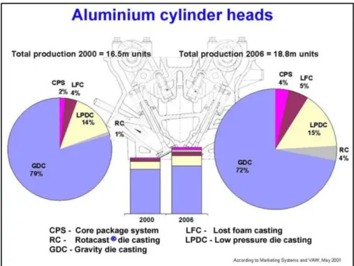
European Aluminium Association (2002) listed the ten casting methods which are used in automotive applications. These methods are green sand casting, core package casting, gravity die casting (GDC), low pressure die casting (LPDC), high pressure die casting (HPDC), vacuum die casting, squeeze casting, thixocasting, vacuum riserless casting and lost foam casting [NN02].
Figure 2.6 shows the trends in market share of casting methods for aluminium cylinder heads. As shown, the biggest percentage of market is covered by gravity die casting method.
Figure 2.6: Trends in market share of casting methods for aluminium cylinder heads [NN02]
2.3.1 Casting of aluminium cylinder heads
Pavlak (2010) stated that the gating system can affect the casting quality and the design of a gating system is important. Metal flows from ladle to the mould cavity through these gates. The selection of a good gating system is even more important if the gravity casting process is used. Poor gating techniques create turbulent flow which is a negative parameter for casting. There are three types of gating systems which could be used in cylinder head production.
Figure 2.7 compares these three different gating systems. Top casting method (Figure 2.7.a) provides a directional solidification process and it helps to get better mechanical properties. On the other hand, turbulent flow is the biggest disadvantage for top casting. Bottom casting method (Figure 2.7.b) has laminar flow when compared to the top casting method. But this time, cooling conditions get worse and mechanical properties deteriorate. In addition to this, shrinkage and gas pores occur in the bottom gating system. Tilt pouring method (Figure 2.7.c) has all advantages of top casting with lower turbulent flow. Other important factors which affect the quality of products are melt temperature, mould temperature, filling time and alloy composition [Pav10].
Figure 2.7: a) Top casting method, b) Bottom casting method, c) Tilt casting method [Pav08] Instead of all casting methods and gating systems, the casting method and gating system used in the experimental method will be detailed in this study. The casting method which is called tilt gravity casting can be listed under the gravity die casting.
Köhler et al. (2010) noted that a variety of casting processes are applied in the production of aluminium cylinder heads. According to the physical principles and the position of the caster, the name of methods shows differences. Tilt gravity casting is described by the caster position which is between 0° and 90°. If the top position angle reaches to 180°, it is called as Rotacast method.
Zero-turbulance flow, low-oxide filling of the mould, directional solidification and fine-grain microstructure with small dendrite arm spacing are demanded for perfect aluminium cylinder heads. The principle of tilt gravity casting is similar to pouring beer into a glass or mug [Koh10].
Smetan et al. (2014) published their study about a new innovative casting process. In last decades, aluminium casting industry is ruled by gravity die casting and low pressure die casting processes. Tilt casting process is relatively new casting process for industry. Figure 2.8 shows this process step by step with respect to time. Pouring process continues around 7 seconds and the solidification of cylinder head finished around 150 seconds.
Figure 2.8: Filling of mould cavity in tilt gravity casting [Sme14]
In the experimental methods section of this thesis, similar approach is used as given by Smetan et al. (2014). As the first step in the experimental approach, the basin is filled by a robot arm from the holding crucible with a very low turbulance (Figure 2.9.a). The filled basin is transported to the mould and the mould is positioned to 0° angle simultaneously (Figure 2.9.b). The filled basin is connected to the mould by robot arm and the filled basin is docked to the mould (Figure 2.9.c). Rotational movement of the mould is started from 0° to 90° angle and the cavity is filled by liquid metal (Figure 2.9.d). This filling process takes nearly 7 seconds as mentioned above. When the angle reaches 90°, rotational movement is finished and the solidification starts after pouring (Figure 2.9.e). Finally, discharged casting basin is undocked from mould by robot arm (Figure 2.9.f) and the process is completed. The discharged basin is cleaned by pressurized air and prepared for the next cycle.
The advantages of this experimental approach are: Extremely low-turbulance flow,
Low-oxide filling,
Figure 2.9: a) Lading and dosing, b) Transporting of casting basin, c) Docking of casting basin, d) Starting of casting, e) Ending of casting, f) Undocking of casting basin [Sme14] The casting process is started with setting of cores. 8 different sand cores are put together into the core holder by the operator. Sand cores will be detailed in the ‘Experimental Method’ section in this study. Cores are taken from core holder to mould by robot in first section of ‘Carousel-Line’. After that, the mould rotates with sand cores as shown in Figure 2.9.b. A second robot arm fills the basin with liquid metal from the holding crucible and attaches it to the mould and so is the pouring process completed in the second section of ‘Carousel-Line’. The mould moves from the second section to the third section for solidification. First robot arm takes the new poured part from the third step of ‘Carousel-Line’ to cooling bands. After cooling down, the part comes to the hammering station. Rosined and pressed sand cores are formed to sand form with hammer pressure. Flashes are sawed before the decoring process for which vibratory mould is used. Sand form cores release easily with vibration after the hammering station. After decoring, runner cutting and feeder cutting processes are done by saw. Finally, the part is taken from the outfeed roller conveyor by an operator. Visual inspection before machining is done by operator. Laser machine marks the part and the casting process is completed.
2.4 Material: Aluminium and aluminium alloys
European Aluminium Association (2011) stated that cast iron cylinder heads have been almost completely replaced by cast aluminium alloys during last 20 years in Europe. Aluminium has the advantages of being light weight, having a high thermal conductivity and being easily machinable as compared to cast iron. The weight reduces around 50% and critical areas such as combustion chamber cool down faster [NN11].
2.4.1 Aluminium and aluminium alloys
Aluminium is preferred for variety of automotive components such as cylinder heads, cylinder blocks, brackets and pistons.
Knirsch et al. (2004) listed the alloys which are used most frequently in manufacturing of cylinder heads. These alloys are G-AlSi6Cu4, G-AlSi7Mg0.3, G-AlSi7Mg0.7, G-AlSi9Cu3 and G-AlSi10Mg(Cu) [Kni04].
In this study, cast cylinder heads made from AlSi6Cu4 are used. The related standard used for the material in this study is DIN EN 1706. The Euro norm is EN AC-45000 and it is chemically in EN AC-AlSi6Cu4.
Chemical composition and mechanical properties of AlSi6Cu4 are given in Table 2.2 and Table 2.3 from the related standard [EN10]:
Table 2.2: Chemical composition of AlSi6Cu4 [EN10]
EN AC-45000 EN AC-45000 Si (%) 5.0 – 7.0 Zn (%) 2.0 Fe (%) 1.0 (0.9) Pb (%) 0.30 Cu (%) 3.0 – 5.0 Sn (%) 0.15 Mn (%) 0.2 – 0.65 Ti (%) 0.25 (0.20) Mg (%) 0.55 Others (%) 0.35 Cr (%) 0.15 Al (%) Reminder Ni (%) 0.45
Table 2.3: Mechanical properties of AlSi6Cu4 [EN10] Temper Designation Tensile Strength (MPa) Yield Strength (MPa) Elongation (%) Brinell Hardness EN
AC-45000 As Cast Min. 170 Min. 100 1 75
As an addition to these tables, Brown (1999) noted that the density of aluminium is 2.70 g/cm2 which is lower than other metals such as iron and copper. A volumetric shrinkage of between 3.5-6.0% which could vary according to the alloys occurs during solidification of aluminium castings [Bro99]. The volumetric shrinkage percentage should be taken into account before mould design with respect to accuracy and defects such as hot tearing and shrinkage porosity.
The alloy content should be designed to get desired properties. Castability, micro structural phases, mechanical properties could be taken into account during the arrangement of content. Silicon, copper, titanium, boron, strontium, magnesium and other metals can be added to get desired properties.
Pavlovic-Krstic (2010) classified the alloying elements into two groups. Major alloying elements control castability and develop the properties. Minor alloying elements refine the phases, modify the structure, affect the solidification behaviour, reduce the oxidation and sprue [Pav10]. On the other hand, Rana et al. (2012) added two more groups that are called modifier elements and impurity elements. Modifier elements modify the phases, influence castability and improve the properties of the structure [Ran12]. Table 2.4 shows the groups of elements which are used in aluminium alloys.
Table 2.4: Major, minor and modifier elements of aluminium alloys [Ran12]
Major Elements Minor Elements Modifier Elements Impurity Elements
Examples Si, Cu, Mg Ni, Sn Ti, B, Sr, P, Mn, Cr Zn, Fe, Be
Actually, Ti and B are known as grain refiners from practical knowledge. Surely, they could be evaluated in the same group with modifiers but it could be more understandable if they are listed under a new group which is called grain refiner elements.
2.4.2 Effect of alloying elements
Silicon (Si): Pure aluminium is not a castable metal and is used in limited applications. Silicon additive improves the fluidity dramatically and is used widely in casting alloys. Because of these, silicon is called a major alloying element. Not only fluidity, but also feeding, hot tear resistances and mechanical properties are improved by silicon addition. Beside all advantages, silicon-rich phases –another expression for hypereutectic alloys- are hard and it causes low ductility and machinability [Bro99].
Kaufmann and Rooy (2004) pointed out another effect of fluidity. Fluidity helps to filling of thin walls and to produce more intricate design and details. It could affect the solidification porosity which is reduced by improved feeding [Kau04].
Copper (Cu): Copper improves the strength, hardness, machinability and heat treatability. Heat treatment is more effective with 4-5.5% Cu in the content and it shows relatively improved casting properties [Kau04]. The addition of copper to Al-Si creates Al- Al2Cu eutectic and/or Al2Cu phases and other inter metallic compounds that increase the strength and machinability of the alloys [Pav10]. On the other side, copper reduces the resistance to corrosion and results in hot tear [Kau04].
Titanium (Ti): Titanium is widely used to refine the grain structure of aluminium alloys. In casting, Ti is used with the combination of smaller amounts of B. Al5Ti1B is widely used in the industry as a grain refiner. It contains 5% Ti, 1% B and Al balance. Soluble titanium aluminides (TiAl3) and insoluble titanium diboride (TiB2) could be reacted by aluminium, titanium and boron. TiB2 is more effective in grain refinement. In the production, Ti additive is
higher than those required for grain refinement to reduce cracking hazard [Kau04].
From the practical knowledge, Ti ratio is between 0.12% (1200 ppm) and 0.16% (1600 ppm) and it is supplied by Al5Ti1B rods. Al5Ti1B rods do not result in finer grains only but also in bright parts. The time of Ti effect is limited around 30-45 minutes. This means, Ti plays important role on grain refinement in first 30-45 minutes after adding Ti into liquid metal. Boron (B): As mentioned before, boron combines with Ti to grain refinement in aluminium alloys. Titanium boride forms interact with active grain refining phases such as (TiAl3) titanium aluminides. Metallic boride reduces tool life in machining and coarse form or agglomerated inclusions show detrimental affect the mechanical properties and ductility [Kau04]. From the practical knowledge, B ratio is between 0.0006% (6 ppm) and 0.003% (30 ppm) and similarly boride is supplied by Al5Ti1B rods.
Strontium (Sr): Strontium uses as a modifier and the effective modification can be done at low levels. This level is around 0.008% (80 ppm) – 0.04% (400 ppm). Higher addition percentage can lead the porosity. Sr could be inactive at low solidification rate [Kau04].
In addition to this, Sr addition improves the Cu distribution in the matrix and Al2Cu distributes and helps to improve the strength [Gop13]. From the practical knowledge, Sr ratio is between 0.008% (6 ppm) and 0.02% (200 ppm) and it is supplied by AlSr15 rods. It contains 15% Sr and Al balance. Sr modified the structure from coarse plate form to refined fibrous form. This modification provides better mechanical properties and elongation.
2.4.3 Al-Si-Cu (3xx.x) system
Table 2.5: Classification of casting aluminium alloys [Pav10]
Casting Alloys
AA Major Alloying Elements Heat Treatment
1xx.x Pure Al. Non-heat treatable alloys
2xx.x Al-Cu Heat treatable alloys
3xx.x Al-Si+Cu/Mg Heat treatable alloys
4xx.x Al-Si Non-heat treatable alloys
5xx.x Al-Mg Non-heat treatable alloys
6xx.x Unused Series Unused Series
7xx.x Al-Zn Heat treatable alloys
8xx.x Al-Sn Heat treatable alloys
9xx.x Al-Miscellaneous Heat treatable alloys
Aluminium alloys are classified into 9 groups with respect to their content. Al + Cu) or (Si-Cu-Mg) or (Si-Mg) evaluated under 3xx.x system. Al-Si-Cu (3xx.x) system is the most widely used in aluminium casting. The percentages of Si and Cu could affect the properties but Al-Si-Cu (3xx.x) has a big advantage for complex casting in the permanent mould among other systems. Other metals such as titanium, boron, iron, magnesium, manganese and zinc are also important in modifying the basic properties. Al-Si-Cu alloys show good casting characteristics, high strength, high hardness and improved machinability. These properties are obtained in the as-cast condition. However, additional heat treatment could be applied and additive elements could be added to get better results. Heat treatment leads the high strength capabilities. Because of all, Al-Si-Cu alloys are used widely in the production of cylinder heads, blocks, pistons and crankcases [Pav10], [Mey97].
![Figure 2.1: The effect of SDAS on UTS-YS of cast cylinder heads in 319 alloys [Zha05]](https://thumb-eu.123doks.com/thumbv2/9libnet/5466925.105661/21.892.264.674.865.1109/figure-effect-sdas-uts-cast-cylinder-heads-alloys.webp)
![Figure 2.16: a) Optical micrographs of gas porosity in cylinder head casting [Bir08], b) Optical micrographs of gas porosity in cylinder head casting](https://thumb-eu.123doks.com/thumbv2/9libnet/5466925.105661/42.892.136.823.421.676/optical-micrographs-porosity-cylinder-optical-micrographs-porosity-cylinder.webp)
![Figure 2.18: a) Optical micrographs of oxide in engine head casting [Kon14], b) Optical micrographs of oxide in cylinder head casting](https://thumb-eu.123doks.com/thumbv2/9libnet/5466925.105661/43.892.153.795.108.338/figure-optical-micrographs-casting-optical-micrographs-cylinder-casting.webp)
![Table 2.9: Mechanical properties of AlSi7Cu3Mg0.35Fe with and without stress relief process [Ren14] UTS (MPa) YS (MPa) Elongation (%) Brinell Hardness (HB) Without Stress Relief (F) 190 130 1 – Fire Face](https://thumb-eu.123doks.com/thumbv2/9libnet/5466925.105661/52.892.114.814.796.1035/mechanical-properties-process-elongation-brinell-hardness-stress-relief.webp)
![Figure 3.14: a) X-Ray inspection [NN12], b) X-Ray photograph of two d 0 =12 mm tensile test specimens](https://thumb-eu.123doks.com/thumbv2/9libnet/5466925.105661/64.892.162.772.797.1071/figure-ray-inspection-ray-photograph-tensile-test-specimens.webp)
