THEORETICAL AND EXPERIMENTAL
INVESTIGATION OF PUNCHING PROCESS OF
DP800 AUTOMOTIVE STEEL SHEET WITH
DIFFERENT PUNCH TIPS
ABDULSALAM ABUBAKER ELAMEN SAIER
2020
MASTER THESIS
MECHANICAL ENGINEERING
Thesis Advisor
Prof. Dr. Bilge DEMİR
THEORETICAL AND EXPERIMENTAL INVESTIGATION OF PUNCHING PROCESS OF DP800 AUTOMOTIVE STEEL SHEET WITH DIFFERENT
PUNCH TIPS
Abdulsalam Abubaker Elamen SAIER
T.C
Karabük University Institute of Graduate Programs Department of Mechanical Engineering
Prepared as Master Thesis
Thesis Advisor Prof. Dr. Bilge DEMİR
Karabuk December 2020
I certify that in my opinion the thesis submitted by Abdulsalam Abubaker Elamen SAIER titled “THEORETICAL AND EXPERIMENTAL INVESTIGATION OF THE PUNCHING PROCESS OF DP800 AUTOMOTIVE SHEET STEEL WITH DIFFERENT PUNCH TIPS” is fully adequate in scope and in quality as a thesis for the degree of Master of Science.
Prof. Dr. Bilge DEMİR ………
Thesis Advisor, Department of Mechanical Engineering
APPROVAL
This thesis is accepted by the examining committee with a unanimous vote in the Department of Manufacturing Engineering as a Master of Science thesis. 21/01/2021
Examining Committee Members (Institutions) Signature
Chairman : Assoc. Prof. Dr. Okan ÜNAL (KBU) ...
Member : Prof. Dr. Bilge DEMİR (KBU) ...
Member : Assoc. Prof. Dr. Hakan GÜRÜN (GU) ... R
The degree of Master of Science by the thesis submitted is approved by the Administrative Board of the Institute of Graduate Programs, Karabük University.
Prof. Dr. Hasan SOLMAZ ...
“I declare that all the information within this thesis has been gathered and presented in accordance with academic regulations and ethical principles and I have according to the requirements of these regulations and principles cited all those which do not originate in this work as well.”
ABSTRACT
Master Thesis
THEORETICAL AND EXPERIMENTAL INVESTIGATION OF PUNCHING PROCESS OF DP800 AUTOMOTIVE STEEL SHEET WITH DIFFERENT
PUNCH TIPS
Abdulsalam Abubaker Elamen SAIER
Karabük University Institute of Graduate Programs Department of Mechanical Engineering
Thesis Advisor: Prof. Dr. Bilge DEMİR December 2020, 66 pages
With the increasing awareness of the importance of automobile lightness, the use of AHSS steels with good lightness, strength and ductility combinations in production has also increased. The increasing of the strength of AHSS steels also limits the application of manufacturing processes such as cutting and punching. One of the most used manufacturing methods during automobile manufacturing is punching. Although it is a simple process, its dependence on many parameters makes it difficult to obtain quality outputs due to optimization studies. Punching process of good quality depends on some parameters such as clearance, punch force, punch speed, blank-holder force and punch tip geometry. The punch force is the most complex one of these parameters, as it is linked to many parameters. The most important parameter affecting the cutting force is the punch tip geometry. Although there have been many studies in the literature on the effects of different punch geometries on punch force, the effects of different
punch geometries on cutting surface properties, which is a quality criterion for punching, should also be examined. As a result of the punching process, the different zones of the cutting surface, significantly affect the stretchability of the part. Cutting surface quality is the most important factor affecting the formation of corner cracks. Therefore, the relationship between punch geometry and cutting surface should be determined and the differences in punch forces caused by different geometries should be examined.
For this study, dual-phase steel grade DP800 steel, which is a most widely used AHSS type, were used. Punch with 5 different tip geometries were used for the experimental studies. The cutting surfaces formed as a result of the experiments to be made at constant clearance and cutting speeds have been examined with the help of an optical and stereo microscope. In addition, the punching process will be examined numerically with the finite element method by DEFORM-3D and SIMUFACT-2D programs, and the effects of stress distributions caused by different tip geometries on the cutting surface will be examined. The damage model will be defined for the material and damage constant will be determined. Thus, damage predictability will be provided for the study. Finally, the consistency of the model will be analysed by comparing experimental and numerical studies.
Keywords : Dual phase steels, punching, cutting surface quality, mechanical
properties. fracture.
ÖZET Yüksek Lisans Tezi
DP800 OTOMOTİV ÇELİK SACININ FARKLI ZIMBA UÇLARI İLE
DELME İŞLEMLERİNİN TEORİK VE DENEYSEL OLARAK İNCELENMESİ
Abdulsalam Abubaker Elamen SAIER
Karabük Üniversitesi Lisansüstü Eğitim Enstitüsü Makina Mühendisliği Bölümü
Tez Danışmanı: Prof. Dr. Bilge DEMİR
Kasım 2020, 66 sayfa
Otomobil hafifliğinin önemi konusunda artan farkındalıkla birlikte, iyi hafiflik, mukavemet ve biçimlendirilebilirlik özelliklerine sahip AHSS çeliklerinin (Geliştirilmiş Yüksek Mukavemetli Çelik) üretimde kullanımı da artmıştır. AHSS çeliklerinin mukavemetinin artması aynı zamanda kesme ve delme gibi üretim işlemlerinin uygulanmasını da sınırlamaktadır. Otomobil üretimi sırasında en çok kullanılan üretim yöntemlerinden biri delmedir. Basit bir süreç olmasına rağmen birçok parametreye bağlı olması, optimizasyon çalışmaları nedeniyle kaliteli çıktılar elde etmeyi zorlaştırmaktadır. İyi kalitede delme işlemi, iki parça arasındaki boşluk, delme kuvveti, delme hızı, pot çemberi kuvveti ve delme ucu geometrisi gibi bazı parametrelere bağlıdır. Delme kuvveti, birçok parametreye bağlı olduğu için bu parametrelerden en karmaşık olanıdır. Kesme kuvvetini etkileyen en önemli parametre, delme ucu geometrisidir. Farklı delme geometrilerinin delme kuvveti üzerindeki etkileri konusunda literatürde birçok çalışma bulunmasına rağmen, farklı delme geometrilerinin delme işlemi için bir kalite kriteri olan kesme yüzeyi özellikleri üzerindeki etkileri de incelenmelidir. Delme işleminin bir sonucu olarak, kesme yüzeyinin farklı bölgeleri, parçanın esneme kabiliyetini önemli ölçüde etkilemektedir.
Kesme yüzey kalitesi köşe çatlaklarının oluşumunu etkileyen en önemli faktördür. Bu nedenle, delme geometrisi ile kesme yüzeyi arasındaki ilişki belirlenmeli ve farklı geometrilerin neden olduğu delme kuvvetlerindeki farklılıklar incelenmelidir.
Bu çalışmada en yaygın kullanılan otomotiv olan AHSS sac çeliklerinden olan DP800 çeliği kullanılmıştır. Deneysel çalışmalar için 5 farklı tipte-geometrili zımba kullanılmıştır. Sabit açıklıkta ve kesme hızlarında yapılan deneyler sonucunda oluşan kesme yüzeyleri optik ve stereo mikroskop yardımıyla incelenmiştir. Buna ek olarak, delme işlemi DEFORM-3D ve SIMUFACT-2D programları üzerinden sonlu elemanlar yöntemi ile sayısal olarak incelenmiş ve farklı zımba geometrilerinin neden olduğu gerilme dağılımlarının kesme yüzeyine etkileri incelenmiştir. Malzeme için hasar modeli tanımlanmış ve hasar sabiti belirlenmiştir. Böylece çalışma için hasar öngörülebilirliği sağlanmıştır. Son olarak, deneysel ve sayısal çalışmalar karşılaştırılarak modelin tutarlılığı analiz edilmiştir.
Anahtar Kelimeler: Çift fazlı çelikler, Zımba ile delme, kesme yüzey kalitesi,
mekanik özellikler, kırılma modu.
ACKNOWLEDGMENT
In the name of Allah Almighty Praise be to Allah. The work was carried out in the Faculty of Technology at Karabük University, between September 2018 January 2021 under the supervision of Prof. Dr. Bilge DEMİR, whom I would like to sincerely thank for his encouragement, guidance and advice throughout the period of experimental work and for constructive criticism during the preparation of this thesis.
I am also especially grateful to Prof. Dr. Hakan GÜRÜN for conducting some experiments at Gazi University. I would also like to thank my colleagues Khalil Bin Ras Ali and Abdul Karim Al Zahuqi for their advice and support, and likewise, I do not forget my colleague Mustafa GÖKTAŞ and all the staff in the department for their assistance.
I thank my mum, dad, brothers, and family for their patience and commendable support while preparing this thesis I would also like to extend my thanks to all of my friends and colleagues, and I wish you all success.
CONTENTS Page APPROVAL ... ii ABSTRACT ... v ÖZET... vii ACKNOWLEDGMENT ... viii CONTENTS ... ix LIST OF FIGURES ... xi
LIST OF TABLES ... xvi
SYMBOLS AND ABBREVIATIONS INDEX... xvii
PART 1 ... 1
INTRODUCTION ... 1
1.1. HISTORY ... 5
1.2. THE OBJECTIVE OF STUDY ... 5
PART 2 ... 7
ADVANCED HIGH STRENGTH STEEL (AHSS) ... 7
2.1. CLASSIFICATION OF ADVANCED HIGH STRENGH STEEL (AHSS) ... 8
2.2. DUAL PHASE STEELS (DP) ... 10
2.2.1. Classification of DP Steels ... 11
2.2.2. Microstructure of DP Steel ... 12
2.2.3. Mechanical Properties ... 14
2.2.4. Relationship between Ultimate Tensile Strength and Uniform Elongation of Many Steels ... 15
2.2.5. Relationship between Yield Strength and Ultimate Tensile Strength for Various Types of Steels (Yield Ratio) ... 16
2.2.6. Processing of Dual Phase Steel (DP) ... 17
2.2.7. Dual Phase Steel in Automotive Industry ... 20
PART 3 ... 22
SHEET METAL FORMING ... 22
Page
3.1.1. Sheet Metal Punching Process ... 22
3.1.2. Punching Operation ... 23
3.1.3. Clearance of Die ... 24
3.1.4. Hydraulic Punch Press ... 25
PART 4 ... 28
EXPERIMENTAL STUDY ... 28
4.1. GENERAL VIEW ... 28
4.2. MATERIAL PROPERTIES OF DP800 STEEL ... 28
4.3. PUNCH GEOMETRIES AND PUNCHING PROCESS ... 29
4.4. PERFORMING PUNCHING PROCESSES WITH FINITE ELEMENT METHOD ... 32
PART 5 ... 34
EXPERIMENTAL RESULTS AND DISCUSSION... 34
5.1. MATERIAL MODEL ... 34
5.2. CUTTING SURFACE PROPERTIES ... 35
5.3. PUNCHING (PIERCING) TESTS ... 44
PART 6 ... 58
CONCLUSION ... 58
REFERENCES ... 60
RESUME ... 66
LIS OF FIGURES
Page
Figure 1.1. Global formability with position of advanced high strength steel ... 3
Figure 1.2. (a) Schematic illustration of shearing with a punch and die, indicating some of the process variables. Characteristic features of (b) a punched hole and (c) the slug ... 4
Figure 2.1. Example of DP steels as safety details in car bodies. ... 10
Figure 2.2. The microstructure of DP800 steel. ... 11
Figure 2.3. The microstructure of DP steel. ... 13
Figure 2.4. Summary of relationship of tensile and tensile elongation for numerous members of traditional and AHSS ... 16
Figure 2.5. Relationship between yield strength and total elongation for many types of steels ... 17
Figure 2.6. Illustration of the lever rule ... 18
Figure 2.7. Intercritical annealing of DP steel ... 19
Figure 2.8. Applications of DP steels in automotive industry ... 21
Figure 3.1. During the six-stage progression of hole punching, impact highest at snap through effect is even greater when penetrate AHSS. ... 24
Figure 3.2. Appearance of a cut edge ... 24
Figure 3.3. Die clearance definition ... 25
Figure 3.4. Hydraulic punch press. ... 25
Figure 4.1. True Stress-strain plot of DP800 sheet steel. ... 29
Figure 4.2. Test setup for punching process. ... 29
Figure 4.3. Flat type punch. ... 30
Figure 4.4. Punch with 15.6 mm diameter flute, R1. ... 30
Figure 4.5. Punch with 10.6 mm diameter flute, R2. ... 30
Figure 4.6. Punch with 16 degree beveled tip, P16. ... 31
Figure 4.7. Double side 16 degree beveled punch, V16. ... 31
Figure 4.8. Displaying of the parameters that are important for punching process. .. 31
Page
Figure 5.1. Comparison of simulation ned from the tensile test DP800 material. ... 34
Figure 5.2. Tensile simulation of DP800 sample with Simufact. ... 35
Figure 5.3. Cutting surface image as a result of punching test with flat punch. ... 36
Figure 5.4. The dimensions of the different regions as a result of 2-D punching. ... 37
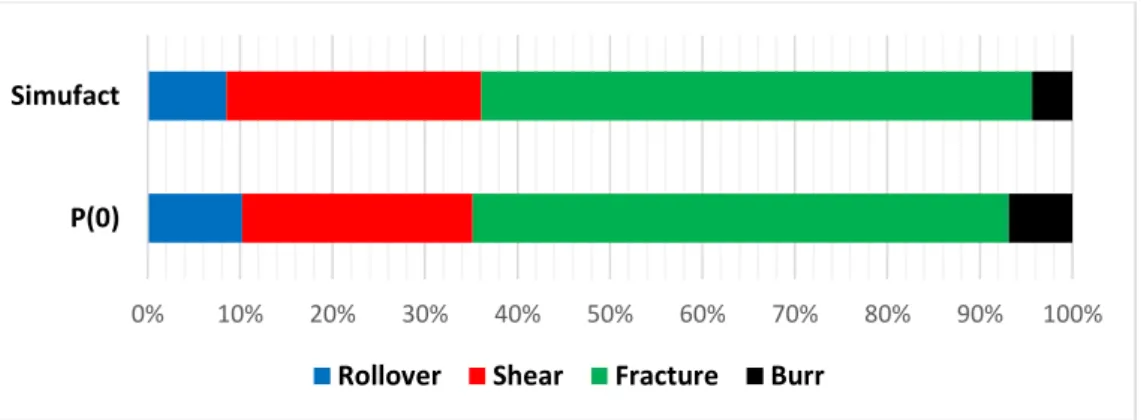
Figure 5.5. Percentage of cutting surface areas experimental and simulation studies. ... 37
Figure 5 6. Cutting surface image, formed of punching performed with P16 punch. ... 39
Figure 5.7. Stress distributions of Flat, R1, R2, V16 and P16 punches Simufact. .. 40
Figure 5.8. The proportional comparison of the cutting surface areas formed as a result of punching processes with P0 and P16 punch. ... 40
Figure 5.9. Cutting surface image as a result of punching test with R1 punch. ... 41
Figure 5.10. Cutting surface image, as a result of punching test with R2 punch. ... 41
Figure 5.11. Cutting surface image, as a result of punching test with V16 punch. ... 42
Figure 5.12. The deviations that occur as a result of hole diameter measurements. .. 42
Figure 5.13. The images of different punches of rollover zonal locations. ... 43
Figure 5.14. Comparison of cutting angles of finite element with punch geometries. ... 45
Figure 5.15. The stress distribution during flat punching process. ... 46
Figure 5.16. The stress distribution during P16 punching process. ... 47
Figure 5.17. The stress distribution on part during R1 punching process. ... 47
Figure 5.18. The stress distribution during R2 punching process. ... 48
Figure 5.19. The stress distribution during V16 punching process. ... 48
Figure 5.20. The force graph obtained from punching process made by flat punch.. 49
Figure 5.21. The force graph obtained from punching process made by R1 punch. . 49
Figure 5.22. The force graph obtained from punching process made by R2 punch. . 50
Figure 5.23. The force graph obtained from punching process made by P16 punch. 50 Figure 5.24. The force graph obtained from punching process made by V16 punch. 50 Figure 5.25. The force values obtained punching process made by different punch. 51 Figure 5.26. The force graph of punching process made by Flat Punch with DEFORM... 51
Figure 5.27. The force graph of punching process made by R1 Punch with
DEFORM... 52 Figure 5.28. The force graph of punching process made by R2 Punch with
DEFORM... 52 Figure 5.29. The force graph of punching process by P16 Punch with DEFORM. .. 52
Page
Figure 5.30. The force graph of punching process by V16 Punch with DEFORM. .. 53 Figure 5.31. Comparison of the graphics obtained from the experimental and
simulation punching process made with flat punch. ... 53 Figure 5.32. Comparison of the graphics obtained from the experimental and
simulation punching process made with R1 punch. ... 54 Figure 5.33. Comparison of the graphics obtained from the experimental and
simulation punching process made with R2 punch. ... 54 Figure 5.34. Comparison of the graphics obtained from the experimental and
simulation punching process made with P16 punch. ... 54 Figure 5.35. Comparison of the graphics obtained from the experimental and
LIST OF TABLES
Page Şekil tablosu öğesi bulunamadı.
Table 2.1. Advanced High Strength Steels ... 9 Table 2.2. Reviews the product property requirements for many types of DP steels 12 Table 4.1. The boundary conditions for punching process. ... 32
SYMBOLS AND ABBREVIATIONS INDEX
ABBREVIATIONS
AHSS : Advanced High Strength steels TWIP : Twinning Induced Plasticity CP : Complex Phase
DP : Dual Phase
TRIP : Transformation Induced Plasticity BiW : Body-In-White
HSLA : High Strength Low Alloyed HSS : High Strength Steel
TRIP : Transformation Induced Plasticity TWIP : Twinning-Induced Plasticity CP : Complex Phase
MS : Martensitic Steel FB : Ferritic Bainitic HF : Hot Forming LA : Low Alloy
PART 1
INTRODUCTION
There were great efforts to decrease the mass of vehicles in automotive industry in order to decrease the consumption of fuel. This is achieved by the use of higher strength steel with great frequency on the structural components of vehicles. Higher strength steel helps to make thinner sections in the car elements that result in lower vehicle mass and enhanced the fuel economy [1]. Recently, dual phase steels are widely used with increased frequency due to their ductility and great strength if compared with other types of steels. The desire is always for higher ductility metal or higher strength steel including magnesium and aluminium, dual phase steel provides the advantages that existed in both previous metals with competitive cost.
Beside ductility and strength, manufacturers seek to save cost in the forming operations. This motivated manufacturers and researchers to search into alternatives to conventional drawings and tamping in automotive industry. High strain rate forming operations is considered one of the most important research areas which witness interest by automotive manufacturing companies. One of these approaches is electrohydraulic forming that is considered a category of forming process which has been studied and searched since the sixties of last century [2]. It is targeted recently due to its popularity to increase the sheet materials formability already used. Electrohydraulic forming provides many advantages such as its requiring to fewer equipment to operate, fewer forming stages and increase the formability of materials already used in manufacturing process. Currently, these advantages are desired in automotive researches. In sheet metal punching process of appliance and automotive industries, the work piece blank is generally equipped by mechanical shearing (which is also called blanking) with high production speed. Operations based on piercing appear in punching the metal sheets to produce geometrical characteristics of final products.
Due to the significance of sheared edge quality to the formability of consequential stamping operations or to the final quality of product, huge amount of researches were performed in classical manufacturing area and huge amounts of literature about mechanical shearing are existed. The sheet metal piercing/flanging has been studied and researched by [3]. This reveals the concerns and problems in the area which involved to the mild steel and low alloy high steel strength and other non-ferrous metals. The main method of the researches and studies was experimental reflection and representation of sheared edges.
In general, the sheared edge includes four areas: roll-over area, burnish area (also called shearing area), fractured (or called ruptured) area and burr area. In many cases, the secondary burnish area may occur depending on the properties of material fracture and blank constraining circumstances. This fast development of new forming techniques, concepts of design, new and good materials enjoy by high solidity and formability has been determined mainly in the automotive sector where the added values of sheet metal parts allow high degree of conducted inventions. Demands to enhance the strength to wright rate resulted in the development of many new types of steels with enhanced strength.
Between the invented types of steels, Advanced High Strength steels (AHSS) are
considered the most important of those types which used currently in automotive industry [4]. AHSS are categorized in accordance their crystallographic structure to many types of steels including Twinning Induced Plasticity (TWIP), Complex Phase (CP), Dual Phase (DP) and Transformation Induced Plasticity (TRIP), as shown in Figure 1.1. Besides to what we mentioned above, the third generation of AHSS steels are currently in use.
Figure 1.1. Global formability diagram with position of advanced high strength steel [5].
The last few decades witnessed great efforts to develop AHSS and their applications especially in automotive industry [6] and reports on special case studies and researches have been developed by the American Iron and Steel Institute and Auto Steel Partnership [7]. The activities of researches and studies in Europe can be found in a review article [8]. Most of AHSS materials including DP steel enjoy by popular structural features comprising fine-grained martensite particles which are inserted inside a ferrite matrix, produced through special thermo-mechanical processes which result in a good mixture of improved strength and formability with low cost. The family of this materials includes globally unified structure but meticulously highly non-uniform in terms of the presence of DP (or many stages) comprising martensitic particles of a little microns or smaller in their size. In terms of DP steels, by chaining the martensitic volume fraction, many strengths can be gotten in terms of formability better than those existed in traditional high strength steel with similar strength and therefore they entered in many applications. AHSS manufacturing witnesses many challenges and one of these challenges is the difficulty to expect the edge cracking in stamping operations and it is considered to associate with both the structure of materials and mechanically sheared edge properties of the blanks. Therefore, the sheared edges of AHSS must be studied and investigated more and more, characterize and investigate their effect on stamp formability.
The previous studies in this regard consist of AHSS [6] who reported the structural impact on the stretch-flange-formability of three cold-rolled ultrahigh strength steels (with strength at 980 MPa grade) such as one Martensite single-phased steel and two DP steels. The Martensite steel presented the highest hole-expansion rate above the two DP steels. The researchers stated that the gradient of strain in expansion of hole played a significant role. In terms of DP steels, the stretch-flange-formability has been affected by the crack propagation path. A weak formability related with the directing micro-cracking along the interface of stage whereas high formability is related to micro-crack propagation inside ferrite and martensite stage. The most important issue of DP steel in terms of stretch-flange-formability is the difference in solidity [9]. Furthermore, another effected factor is the stage volume fraction. The blanking operation is commonly used to industrialize the sheet metal parts of different materials. Generally, the cut components are subjected to more plastic researches but there are those which directly used in the assembly process of composed products. Many works presented the blanking of components with punch of flat surface have been very well offered as clarified in Figure 1.2 [10].
Figure 1.2. (a) Schematic illustration of shearing with a punch and die, indicating some of the process variables. Characteristic features of, (b) a punched hole and (c) the slug [11].
1.1. HISTORY
A consortium of thirty-five sheet steel producers started in 1994, the Ultra-Light Steel, Auto Body (ULSAB)W-1 program to design a lightweight steel auto body structure which may satisfy a extensive range of safety and performance target illustrated in Figure 3.1. In 1998, the Body-in-white (BiW) has been unveiled to validate the program concept design [12] and ULSAB proved to be physically sound, executable lightweight, safe, as well as reasonable. One of the main suppliers to the success of ULSAB was a set of new types of steels and grades which are known as Advanced High-Strength Steels (AHSS) (10). The family of AHSS enjoy by distinctive and unique microstructure using phase transformation and complex deformation processes to fulfil the combination of ductility and strength that never achieved before. The other important feature of these materials is that they use present stamping and assembly fabrication equipment and production approaches [13]. During the following years, AHSS success in automotive industry encouraged steel firms to keep pace their studies and researches on grades and new types of AHSS and then use these steel in different fields of production [14].
DP steel is the pioneer of AHSS that were the first between several candidate alloys systems used in many applications in weight-reduced automotive elements. This is considered a success story in metallurgical. It allows the use of less material to achieve more performance while observing with demanding economic and environmental restrictions. Instead, the huge amounts of literature associate with DP steel demonstrates the immense complexity of structure physics in multi-phase alloys: nearly fifty 50 years after the first studies on ferrite-martensite steels, there are still many open technical questions. Moreover, the last few decades witnessed many development on allowing simulation and experimental techniques expressively enhancing the DP steels understanding [15].
1.2. THE OBJECTIVE OF STUDY
Steel is considered as one of the most significant structural materials and can be developed and used many engineering fields including energy, transportation and
infrastructure. Developments in these fields come by developing AHSS. Strong demands in automotive industry to anti-collision materials fuel effectiveness appears to the scientific and engineering interest of AHSS. DP is one of the oldest identified types of AHSS. However, researches and studies on DP steel have not presented a total understanding to the properties of this material. The complex structure of DP steel increases many scientific questions about this important metal.
This chapter presents the literature on the effect of punches on DP steel and the effect of its unique strength. Like other forms of forming, the application of stamping operations and their modelling by reformulating computer programs with partial elements can offer an outstanding real focus to change and synthesis work and testing work. In written consideration, it can be seen that punching DP steel with special types of punch is not feasible, and the use of imitations will be the first time. To this end, the focus of this research is to hypothetically use testing and limited component strategies to test the punching handles of DP800 steel plates used in the automotive industry. The test complies with EN ISO 14273 measures. The punching process will be conducted with unique staples. The effect of replacing the punching tool on the punching process will be reviewed in this chapter. The experimental and theoretical research on the punching of DP800 steel plates with different punches is reviewed in this chapter. Firstly, it is summarized by showing the features, problems and manufacturing approaches of DP steel. The following sections describe the process of forming metals. Next section presents the results of simulating the FEM process of DP800 steel. Finally, the third part introduces experimental research, stamping in the automotive industry and some mechanical tests on metals that will be used in this research.
PART 2
ADVANCED HIGH STRENGTH STEEL (AHSS)
AHSS are engineering materials which including many characteristic and the most important of them are the combination between excellent energy absorption (crashworthiness), good ductility (formability) and higher strength (performance). Today, the world demand about energy saving, concerns about global warming effect and environmental pollution impacted on the scientific society and associate studies are increasing day by day. The enhancement of strength, materials properties especially metals, capacity, decreasing material cross section, the decrease of part weight and the subsequent decrease in fuel consumption have made possible to decrease greenhouse gas emissions. AHSS is considered the optimal solution for numerous functional requirements of the existing vehicles [16].
During the eighties of the last century, automotive industry faced many obstacles to improve safety, decrease consumption of oil and weight, durability, viability, exhaust gas pollution, fuel efficiency, good formability, environmental policy and quality demands at reasonably low cost [17]. Steel makers agree that AHSS is a new generation of steel which provides very high strength and other useful mechanical properties while stabilizing high capability. AHSS combines between strength and ductility by transformation of phase and solution strengthening and achieve a strength-to-weight ratio at light applications in the automotive industry [16,17]. The steel is classified by the use and carbon content. Carbon steels (0 – 0,30 wt% C) are the most important metal for structure safety and integrity as they structure the car body in White (BIW). The properties of plain carbon steels majorly depend on their content of carbon and microstructure. The main useful impact of these alloying components is increasing strength and hardness besides the hardenability of material. Basically, the stiffness is not stimulated [18].
The quality, microstructural homogenous and low content of carbon for plain carbon steel provide great importance and good formability in automotive industry. However, increasing the strength of vehicle in automotive industry is an important task for the performance issues. Strength can be increased by cold working. Although this is limited due to the chemical structure of the steel. Increase the alloying level will increase the cost and effect positively on the formability. High Strength Low Alloyed (HSLA) steel has been developed to improve the hardness and strength of steel and keep good formability simultaneously [19]. Generally, low alloyed steels include manganese and silicon and may present high strength and good formability simultaneously, if they are first hear conserved to create a matrix of ferrite with islands of martensite [20]. AHSS collects between strength and ductility by solution reinforcement and phase transformation and achieve a strength-to-weight ratio of light applications in the automotive industry.
2.1. CLASSIFICATION OF ADVANCED HIGH STRENGH STEEL (AHSS)
AHSS access into much higher tensile strength if compared with the traditional High Strength Steel (HSS). Strength-ductility relationship is one of the most significant and valued properties of HSS. AHSS includes many types that can be classified according to the mechanical properties of the material and processing. Currently, the most used types of these materials are Transformation Induced Plasticity (TRIP), High strength low alloy (HSLA), martensite (MART) twinning-induced plasticity (TWIP), complex phase (CP), dual-phase (DP), martensitic steel (MS) and Ferritic Bainitic (FB) [21]. Between the properties related to equipped 590R, there are improved formability together with high strength has satisfied wide range of applications in automotive industry. This new types of steel was developed depending on a stable weldable alloy with low carbon levels and alloying components [22]. Bouaziz et al. (2013), keeler et al. (2014) and Kuziak et al. (2008) mentioned that high-definition path and types of AHSSs are families of steels which are stronger and have higher ductility or formability than the traditional HSSs,
There is possibility to differentiate between the AHSS family and the strength levels which can be unevenly defined: product yield strength> 300 MPa and ultimate tensile>
600 MPa. Lower fuel consumption is considered a main element in decreasing the weight of car [24]. Light vehicles have been developed with high quality using high level of steels for example multiphase steels. These consist of perfect selection of DP steels that its structure is consisted mainly of martensite and ferrite to low yield strength applications, high tensile strength, continuous result, and identical elongation need the main materials of AHSS are DP and TRIP steels. Many other types of AHSS have been developed and all of which have structure including two or different stages one of them adds strength and ductility to the materials whereas the others provide more formability as clarified in Table 2.1.
Table 2.1. Advanced high strength steels [67].
AHSS Microstructure Composition DP Dual Phase steel ferrite, martensite [LLewellyn & Hudd
2000]
TRIP Transformation Induced Plasticity steel
ferrite, bainite, retained austenite [LLewellyn & Hudd 2000]
CP Complex Phase steel martensite, pearlite, retained austenite [IISI, 2006]
FB Ferritic Bainitic steel ferrite, bainite [IISI, 2006]
MS Martensitic Steel martensite, bainite, ferrite [IISI, 2006]
Q&P Quenching & Partitioning steel
martensite, ferrite, retained austenite. [Wang & Weijun, 2011
Since TWIP and HF steels sometimes showed improved strength and formability, they are grouped under the heading AHSS [24]. However, they do nor consist a composite structural composition that sets HSLA steels apart from AHSS steels. Furthermore, while the chemical structure of TWIP steels consist of high content of manganese (17 - 24 %), they are not classified as carbon-steels. The microstructure is not the only characteristic which through AHSS can be categorized but they categorized based on the application. In addition, they can be classified based on the mechanical properties,
material thickness and the chemical composition. In Europe, the main feature of AHSS is known as the Euro norm.
2.2. DUAL PHASE STEELS (DP)
This type of steel refers to the group of high strength steels which is categorized into two phases normally a ferrite matrix and a dispersed second phase of martensite, reserved austenite and/or bainite. DP steels have been developed during the seventies of the last century. The motivation behind the development of this type of steels is the need to a new high strength steel without decreasing the formability or increase the cost. Particularly, automotive industry needed grades of steel with high tensile elongation in order to confirm formability [25], high tensile strength to generate exhaustion and crash resistance, low content of alloy to confirm weldability without effecting cost of production. After many years of use, the demand on DP steel is continuous with increase [26]. These types of steels combine between good formability and high strength and therefore decrease the vehicle weights and other products provide economic and environmental benefits. DP steels present higher properties if compared with HSLA. As a result, to the combination between high deformation toughening, good formability, low cost and high strength as shown in Figure 2.1.
Figure 2.1. Example of DP steels as safety details in car bodies.
The most popular method to produce DP steel is by cold rolling of Low Alloy (LA) steels followed by intercritical annealing in a constant annealing line, here denoted to as CAL. The intercritical term denotes to the two-phase field of austenite/ferrite in the
Fe-C scheme. The austenite stage will be transformed into martensite when quenching, delivered the appropriate solidity of the steel and efficient cooling ratio. This will be resulted in a soft continuous phase of ferrite1 with imbedded hard particles of martensite [26]. Figure 2.2 shows the microstructure of DP steels.
Figure 2.2. Picture of the microstructure of DP800 steel. Using the in-lens detector the hard martensite phase appears as white areas and the soft ferrite phase is dark.
2.2.1. Classification of DP Steels
DP steels include many types including DP 1000, DP 800 and so on according to the eventual tensile strength. The tensile strength of DP steels is over 800 MPa for DP 800 and 1000 MPa for DP 1000 which is greater than the conventional high strength steels that range between 400 - 440 MPa. Nevertheless, they are considered an optimal selection in automotive industry with same production strength [27,28]. So, it can use more than DP sheets which decrease the weight of car without losing their strength. As well as they characterize by higher or similar energy accident absorption. Manufacturers agree that, designing high-level steel-based parts of AHSS provides the chance to decrease the cost of production and vehicle decoration. Presently, DP and TRIP steels are well created as AHSS. Generally, they registered decrease of weight for about 30-40% for 1300-1500 MPa steels [29]. Currently, these properties are included in DP 800 steel and preferred. Furthermore, it is important to get the thermal features of vehicles and other products such as formation, welding, etc. The mechanical properties of DP cold-forming steels change rapidly when the temperature is increased which lead to loss the load bearing capacity of DP-shaped cold steels [28].
Thus, design the structure of DP-shaped steel need knowledge to understand to the thermal properties of the mechanical properties with increasing the temperature. Therefore, it is significant to understand well the thermal properties related to yield strength and DP 800 elastic module with high temperatures. An experimental study has been conducted to analyse the mechanical characteristics of DP 800. Tensile tests have been performed by means of fixed state test approach for temperatures at the range of 20 oC. Many types of DP steels are shown in Table 2.2.
Table 2.2. Reviews the product property requirements for many types of DP steels, according to ArcelorMittal standard 20×80 mm ISO tensile specimens (thickness: less than 3mm) [30].
Steed grade Yield Strength (YS) [MPa] Ultimate Strength (UTS) [MPa] Total Elongation [%] Direction DP450 280-340 450-530 %27 Transversal DP500 300-380 500-600 % 25 Longitudinal DP600 330-410 600-700 % 21 Longitudinal DP780 Y450 450-550 780-900 % 15 Longitudinal PD780 Y500 500-600 780-900 % 13 Longitudinal DP800 494-530 800-830 15.4 Longitudinal DP980 Y700 700-850 980-1100 % 8 Longitudinal 2.2.2. Microstructure of DP Steel
The traditional structure of DP steels includes of the polygonal soft ferrite matrix and that of a 10–40% of the hard martensite island. The strength and ductility of the steel are shown in Figure 2.1. This type of structure helps to achieve the highest tensile strength extending between 500–1200 MPa.
When the volume fraction of the martensite exceeds the 20%, of DP steels that frequently denoted as; the partial martensitic. In order to achieve the personalized requirement, the ferrite-bainite-martensite have been established to modify the mechanical properties. It is detected that bainite instead of martensite improve the formability to little decrease to the development and strength [31].
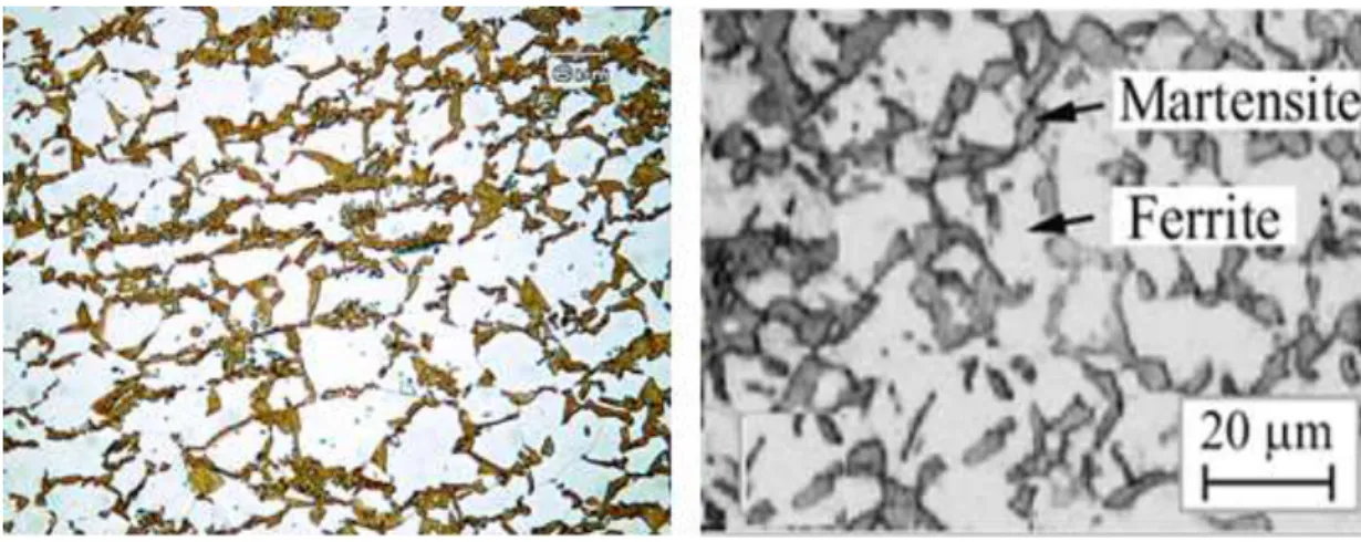
Martensite fraction effect, spread, size of zone, effect of the ferrite fraction, size of grain of the mechanical behaviour of DP steels have been widely researched and studied [32]. Figure 2.3 gives a clear example on microstructure of DP steels. The soft ferrite phase is shown in white microstructure and hard martensite phase is shown as the dark region.
Figure 2.3.The microstructure of DP steel.
Precisely, DP steels started in low or medium carbon steel and it is decreased from the temperature beyond the A1 temperature but under the A3 temperature on a continuous cooling alteration arrangement. Nevertheless, this result is in the structure that includes a soft ferrite matrix which consists islands of martensite as the secondary phase (the tensile strength is increased by martensite increases). Moreover, the comprehensive behaviour of DP steel is controlled by the content of carbon, volume fraction, the grain size and morphology. In order to accomplish these microstructures, DP steel normally consist 0.06–0.15 % C thus strengthening the martensite and the stabilizing austenite phases. The percentage 1.5-3% Mn causes stabilize to the austenite phases and strength in the ferrite. It is supposed that the formation of pearlite or bainite is delayed by the molybdenum and chrome.
The ferrite transformation is promoted by the Si. The reason behind the precipitation strengthening and microstructure refinement are the elements of Nb and V. Furthermore, the distribution of martensite effects the mechanical behaviour of DP steels [33,34].
The martensite regions exist as separated areas within the ferrite matrix results in a further enhanced mixture of the strength and that of the ductility than that of the martensite zones which form a chain-like network structure adjacent ferrite [33]. The refinement of ferrite or/and martensite zones simultaneously enhances the strength and ductility.
2.2.3. Mechanical Properties
The automotive industry needs steel grades with high tensile elongation to ensure the high tensile strength and viability to generate fatigue and crash resistance, low alloy material to ensure that formation will not make an impact on production of cost. Martensite amount phase is considered a significant element control the mechanical characteristics of DP steels; for instance, DP steels have number specific properties such as low yield strength (i.e. 0.2 percent offset), typically high uniform and comprehensive elongation, continuous yielding behaviour (no yield point), high work-hardening rate, high tensile strength (up to 1000 MPa) and [36]. The use of DP steels is continuous and still needed for several years in the future. DP steels have succeeded for many reasons such as combination between high strength and good sustainability and thus, they lead to decrease the vehicles weight and other products have numerous and environmental advantages. As clarified earlier in Figure 2.2 that the comparison between DP steels and HSLA presented that DP steels show better characteristics than others.
The economic demand of fuel reduction in automotive industry encouraged manufacturers to search on new materials to be used between other strategies [37]. The new materials have been evaluated for higher strength or light in order to decrease the vehicles weight have been approximated which result in reducing consumption of fuel. Precisely, TRIP steels enjoy by the demanded ability to absorb more energy
through car accidents due to the deferred transformation of reserved austenite to martensite up on deformation. Combination between strength of TRIP steels, ductility and formability compared with conventional steel can be accomplished by the careful design of structure. The fraction volume, chemical constituent, size and shape of the micro-structural elements principally retained austenite were significant in the tailoring of the mechanical characteristics of TRIP steels [38]. Due to the microstructure, TRIP steels present higher uniform and total elongation with an equal level of strength as DP and conventional HSLA steel which have been clarified. Current researches and studies focus on microstructure, Nugget formation and mechanical characteristics of the AHSS welded resistance particularly on explanation of a single steel grade reply. Similarly, Tong et al [58] examined the mechanical characteristics of DP-spotted steels and their effect on failure behaviour. Nevertheless, the present studies and researches fail to make an accurate comparison between microstructure of spot occurrences and mechanical properties in various levels of AHSS.
2.2.4. Relationship between Ultimate Tensile Strength and Uniform Elongation of Many Steels
The stress strain curves of DP and TRIP steels show high tensile strength, low yield to tensile strength rate, cumulative elongation, continuous yielding and a high uniform as shown in Figure 2.4 [59]. This behaviour can be recognized through the DP steels by the martensite in the ferrite matrix. The martensite convoys by increasing volume because it is shaped through the transformation from the austenite. The ferrite matrix is deformed due to the locally volume increase that led to mobile movements in the interface of the ferrite/martensite, compliant continuous yielding. The hard martensite increases the eventual tensile strength [60]. In TRIP steels distortion through the tensile load causes the reserved austenite to change to martensite. Furthermore, this transformation consists volume extend that result in a partial increase of the strain toughening element. This leads to delay the emergence of necking, higher uniform and full elongation [61].
Figure 2.4. Summary of relationship of tensile strength (UTS) and tensile elongation (Uniform) for numerous members of traditional and AHSS
[68].
Thus, the excellent mechanical properties in automotive industry include the provision of decreasing the weight of the body, energy efficiency, better passive safety, and good viability. In2007, the regular vehicle had 11.6% of medium-sized and high-trust steel and the entire steel material was 57%. Because of increasing the use of AHSS in different practical applications, the research resulted in enhancing its mechanical performance in fewer amounts. Thus, engineers today face many challenges to select the suitable combination of intensity, ductility, strength, and properties of Fatigue.
2.2.5. Relationship between Yield Strength and Ultimate Tensile Strength for Various Types of Steels (Yield Ratio)
It is important to notice that; the Martensitic MS steels are used in various industries and can be seen in many applications such as of harvesters, ground helmets, cranes, and more. The conventional HSSs including low-level alloy (HSLA) have been existed fro0m more than thirty years and have experience to construct technological base. The users of AHSS asked the quick accumulation of information and distribution because they apply these new types of steels. The strength of total yield and elongation axes present an important challenge. As shown in Figure 2.4, that the steels with high
strength reduced elongation ratio. At present time, researchers and manufactures try to find methods to keep the percentage of total elongation with high strength steels.
Figure 2.5. Relationship between yield strength and total elongation for many types of steels [19, 38].
2.2.6. Processing of Dual Phase Steel (DP)
In recent years, DP steels development were witnessed great interest in automotive industry. Precisely, the DP steel is produced from a low or medium carbon steel (0.05-0.2 wt. %). This is resulted by the production of steel with potential weight reduction using cheap alloying without losing the mechanical properties. Generally, |DP steel is made up of two phases which are ferrite and martensite. Nevertheless, in addition to the martensite, the DP steel microstructure consists small amounts of other phases including pearlite, retained austenite and new ferrite depending on the thermos-mechanical processing and cooling ratio. The DP steels have been generated by some authors by heating the steel up to austenite in the iron-carbon phase diagram, then direct quenching from temperature over Ac1 temperature (i.e. inter-critical temperature). However, below the A3 temperature on a constant cooling transformation diagram and is reserved to full austenitic microstructure as shown in Figure 2.6. Later, the steel will be cooled to the ferrite + austenite area and stay at that temperature degree and thus, the ferrite can be nucleated at the austenite boundaries. After nucleation, the ferrite produces to the austenite grains. Therefore, the microstructure will be decorated by the ferrite and martensite phases. Also, DP steel has been generated by other researchers based on and derived from the CCT diagram
that covers slow cooling (air) up to the preferred ferrite transformation from austenite and then quenching for converting the continuing austenite to martensite [62,63]. It has been reported about limited works to produce the bainite/ferrite or martensite/ ferrite microstructure of DP steels by first performing laminar cooling then ultra-fast cooling up to coiling temperature and then by coil cooling until the room temperature of hot rolled strip strictly [46].
The DP steel melt is created by oxygen top blowing operation at the converter and it exposes to an alloy treatment in the secondary metallurgy operation [39]. DP steels are produced by many ways and the common way is through the cold rolling of the low alloy steels that is followed by inter-critical annealing in a continuous hardening line. The inter-critical denotes to the two-phase field of austenite/ferrite.in the (Fe-C) diagram. The quenching determines the transformation of austenite phase to martensite and it is provided in appropriate hardenability. The results is the structure of a soft continuous of ferrite and entrenched hard elements of the martensite which has been detected in the study [40]. The martensite will configure lath or plates based on the carbon content in austenite before to satisfying [41].
Figure 2.6. Illustration of the lever rule [42].
Many practical applications used the sequential quenching process such as suspension components, bumpers, and wheels. As shown in Figure 2.7 that the intercritical annealing process, is normally used to thin sheets. The primary of the microstructure
of sheet comprises of a ferrite-pearlite mixture that is turned to cold with the preferred thickness. The sheet is heated to the ferrite-austenite area where the suspension of pearlite arises. This process is usually too fast be studied deeply [43]. The dissolution of pearlite with most low carbon steels takes from fifteen seconds to two minutes. Increasing the temperature of intercritical annealing increases the size of austenite decrease the content of carbon for the steel resistance and austenite.
Figure 2.7. Intercritical annealing of DP steel [44].
In general, retained austenite is presented at the edges of martensite islands because austenite reverting to the ferrite by cooling. Ferrite discards the carbon in the austenite because it refrigerates which decrease the martensite finish temperature to be under the room temperature [45]. The comparison of both operations, it can be seen that intercritical annealing operation austenite nucleates and grows at ferrite grain boundaries; in successive quenching, ferrite nucleates and grows at the austenite grain boundaries. The annealing time (holding time) determines the fraction of volume along with the cooling and temperature rate. In the higher annealing temperature, the content of carbon in the austenite will be decreased but the volume fraction of austenite itself will be increased. The intermediate quenching is the third less familiar approach to produce DP steels.
At this operation, the steel must be heated to the austenitic area and held approximately 30 minutes to prove that the microstructure consist of the austenite only. Then, it is quenched to the temperature of the room which forms the total structure of martensitic. The sample must be heated for about 60 minutes in the ferritic/austenitic area to form
ferrite at the particle borders. At the end, it is quenched in order to transform the austenite back to islands of martensite to complete the DP structure [46]. This operation associates DP steel with the content of higher martensite in mineral and mining parts which does not need welding processes.
2.2.7. Dual Phase Steel in Automotive Industry
DP steels is the pioneer of AHSS where the first steels between many candidate alloys systems were to find applications in weight-reduced automobile elements. Instead, this is considered a success story in metallurgical. Lean and simple thermos mechanical treatment allow the use of less materials to achieve better performance and obey to the economic and environmental restrictions. Moreover, the huge literature of DP steels proves the immense difficulty of structures behaviour in multiphase alloys. After fifteen years of the first studies on ferrite-martensitic steels, there are still many open scientific questions which have been answered yet. The good new at this regard is that during the last decades, DP steels witnessed great development that significantly enhanced the concept of DP steels.
Recently, DP steels are commonly used in the automobile manufacturing. Currently, this automation form is increasingly used by the automated people to increase the structural elements of HSLA. The most popular AHSS is the Dual-stage steel (DP) because of many features such as continuous yield and quick working increase, the good viability and ductility with comparatively high strength, non-aging behaviour at ambient temperature and low tensile yield ratio [47][42]. When design with DP steels as with other types of AHSS, the most significant thing that must be taken into consideration is the pressure and increase of baking. DP steels can be developed with a high low tensile yield rate (YTS), allowing a widespread set of applications starting from a crumple area to the structure of body. Occasionally DP steel is chosen to make the body structure and the visible parts including doors, hoods, front and rear railings. also, DP steel is used in more popular applications such as corrugated reinforcements, beams and cross-members, slab, and pillars; cowl inside and out; crush cans; shock towers, fasteners and wheels [48,49]. Figure 2.8. Shows many DP grade applications which are used in automotive industry.
PART 3
SHEET METAL FORMING
One of the most significant industrial process is the sheet metal forming. Particularly, this is significant for automobile manufacturing where the sheet metal forming occupies great importance at this position. Automobile manufacturing is the pioneer sector and main driving force in many countries, and it is the main motivation behind the sheet-metal-forming developments.
The competition in car manufacturing is extremely strong leading to larger model variety and shorter model design cycles. The increased competition also leads to a very intense development activity to increase productivity and to reduce costs. Application of light-weight design principles is one of the most important trends to meet the above-mentioned requirements. Obviously, the new design concepts require new materials. The new materials often require new, innovative forming processes and new tooling concepts, as well.
3.1. PUNCHING (PIERCING AND BLANKING)
3.1.1. Sheet Metal Punching Process
In modern industry, the sheet metal punching is considered one of the most popular manufacturing processes. The punching operations may include the occurrence of many failures including tool misalignment, slug jamming, broken tool and tool wear. The previous failures may deteriorate the holes quality or interrupt the monitoring of production line of the punching process is become more and more significant to reveal and correct the failures of punching in time, ensure the product consistence of quality, and protect the tools from destruction. Punching of sheet metal is considered a high transient operation which usually continuous for dozen milliseconds only or even
shorter time. How to efficiently collect experimental data and extract the properties which will illustrate the punching process is significant to the process health monitoring. The force of stamping is considered one of the most significant variables in metal forming or stamping process. Controlling the force of stamping is the efficient and direct approach for control and process monitoring [51].
3.1.2 Punching Operation
The punching is a cutting process through which the material is removed from a piece of sheet metal by applying adequately strong force. The punching operation looks like the blanking except that in punching operation, the removed material is scrap and leaves after the preferred internal properties in the sheet including a slot or hole. The punching is used to create holes and cut outs for many sizes and forms. Punches holes are existed with many simple geometrical shapes (such as rectangle, square, circle, etc.) or combination between each of them. These punches include edges and some of them consist of burrs of not being cut but they are fairly with good quality. Frequently, the secondary finishing are conducted to reach into smoother edges. Each time the punch enters the die, the punching operation removes waste from the metal workpiece. The process leaves hole in the metallic workpiece. The cross-sectional size and shape of the punch regulate the formed hole shape and size in the workpiece [52]. The agglomerates in the holes are dropped into container through a moulding process or recover the agglomerates. When the punch moves upward again as clarified in Figure 3.1, the perforation process is separated into six phases. Please pay attention to the impact of the material when the punch is hit. This effect is more obvious when piercing high-strength materials. The shock wave is high during impact, then begins to flatten, and becomes more controllable as it penetrates. When the punch penetrates the material, the impact load is reduced. The paper may be pulled out. In this case, the peeler releases the paper from the punch of hole. The higher the cutting rate of the paper edge, the better the quality of the edge. When the punch wears out, the frequency of bullets or pull tabs will be higher, and the quality of the holes will be deteriorated [53].
Figure 3.1. During the six-stage progression of hole punching, impact is highest at snap through effect is even greater when penetrate AHSS.
3.1.3. Clearance of Die
The clearance of die is the radial distant between the die and punch as shown in Figure 3.2. As shown in Figure 3.3, the edge is usually characterized by four divisions. If we compare between blanking and punching in mild steel, the selection of die clearance has superior impact of life of tool. Nevertheless, the formation of burr is small and not importantly influenced by changing the die clearance [54]. Increasing the die clearance will increase the fracture area and rollover but less than with mild steel.
Figure 3.3. Die clearance definition [54].
. 3.1.4. Hydraulic Punch Press
Hydraulic punch presses that power the ram with a hydraulic cylinder instead of the flywheel are either valve and feedback controlled or valve controlled.
Valve controlled machines frequently permit one stroke process permit the ram to stroke up and down when ordered. Controlled feedback systems permit the ram to be correspondingly controlled inside immovable points when ordered. This permits better control over the stroke of the ram and increases punching ratios as the ram no longer has to broad the conventional full stroke up and down but can operate inside very short stroke window.
Figure 3.4. Hydraulic punch press.
There are many studies about punching process. A few studies presented below about AHSS and different materials. The one of the most important points in punching/blanking processes are cutting surface properties and punching force. Hence most of studies were made on cutting surface properties and punching force.
Shih et al. [55] In their study they investigated the effects of punches with bevelled geometry on the properties of the cutting surface and hole stretchability of AHSS steels with hole widening tests. As a result of the studies, it has been observed that the cutting force decreases significantly in bevelled punches compared to the flat punch. They also observed that the amount of clearance affects the shear force. As a result of the optimization studies, it has been determined that optimum quality is achieved with 3-degree and 6-3-degree angle punch, 17% clearance and cutting direction parallel to the rolling direction for AHSS steels.
Myint et al. [56] In their studies, tried to determine a damage constant using different damage models, Cockroft-Latham and Oyane, in order to predict the cutting surface properties in fine blanking process. As a result of FEM studies that was used SPCC material for experimental studies, damage constant C was obtained between 1.39-1.5 for Cockroft-Latham model and 0.9-0.96 for Oyane damage model with different clearance values between 1-25%. It has been observed that increasing the punch corner radius, decreases the amount of shear zone.
Mackensen et al. [57] Used different AHSS steels grade like DP800, TRIP700 and TWIP1000 in their studies, using different parameters to reduce punch forces. In the studies, 5,10 and 15% as clearance, 0 º, 2.5º and 5º degrees as punch angle and 5º, 10º, 15º sheet placement angles were used. As a result, in the experiments conducted with 2.5º and 5º angled punches on different AHSS grades, it was observed that there was a decrease in punch forces around 90%.
Hambli [23], in his study, made a blanking process between 5-20% clearances on 0.6% C metal sheets which has between 1.5 and 3 mm thickness. As a result of his studies, the lowest force was observed at 10% clearance value. In addition, he emphasized that to minimise fracture angle and fracture depth, clearance value should be 5%.
Chiriac et al. [58] in their studies, they punched DP780IBF steel with 6 degree bevelled punch-0 degree flat punch and %15 clearance ,to examine the quality of cutting surface. After punching operation, they made expansion test between %22-27 to investigate cutting surface behaviours. As a result of their study, they observed that different punching parameters can affect the depth and work hardening level. Also, they observed in hole expansion tests that the fracture initiated generally in fracture zone then propagate through burnish (shear) zone to rollover zone.
Behrans et al. [59] in their studies, they investigated the effect of punching speed on punching force. They used AHSS grade DP1000 steel for their studies. After numerical and experimental tests, they reached the conclusion that punching speed does not affect to punching force significantly. They stated the reason of that can be increasing the temperature of cutting locations, correspondingly increase the yield point with the temperature.
Hambli et al. [60] in their studies, they developed a calibration method to obtain reliable ductile damage constant. With this method, the cutting surface properties which has obtained from FEM studies with empirical damage constant, compared with the cutting surface properties obtaining from experimental studies. Damage constant is changed, and FEM analysis is repeated until the consistence is obtained. Consequently, reported that with this method optimum damage constant can be obtained and this method can be used for blanking operations.
PART 4
EXPERIMENTAL STUDY
4.1. GENERAL VIEW
Many manufacturing methods are used to produce DP steel parts, which are commonly used in automobile industry. One of the known methods among these methods is punching. Punching is a very difficult manufacturing method to understand due to complexities in the punching process such as excessive local deformations, high strains and formed temperature. DP steels, which are commonly used in automobile industry, were used in this thesis study. In the study, DP800 sheet steels were punched at certain parameters with punches with different tip geometry. Force graphs were obtained for each punch during the punching process. Moreover, DP800 material model was created and numerical simulation studies were performed on Simufact and Deform finite element programs under the same boundary conditions. The obtained force values were tried to be compared with each other and with experimental studies. Finally, the performance of the punches was evaluated in line with the data obtained.
4.2. MATERIAL PROPERTIES OF DP800 STEEL
For the studies, the commercial DP800 sheet steel of 500x500x1.5 mm was cut t small pieces in 100x30mm dimensions according to EN ISO 14273 standards. The following stress strain curve was obtained from the tensile test performed at 2mm / min jaw speed to determine the material properties. As can be seen from Figure 5.1 stress-strain plot of DP800 sheet steel, maximum stress value is approximately 900 MPa and tough material. Also observed that it exhibited consistent elongation properties.
Figure 4.1.True Stress-strain plot of DP800 sheet steel.
4.3. PUNCH GEOMETRIES AND PUNCHING PROCESS
A hydraulic press machine is used for punching operations. The experimental setup integrated into the computer to record force data during the punching process is illustrated in Figure 4.2. As shown in figure 4.2, the force data received through the loadcell with high power capacity were processed through the A / D convertor and recorded via computer software. While 5 different punch types were used for punching operations, the punch speed, and the distance (clearance) between the punch and die were kept constant.
Figure 4.2. Test setup for punching process.
Figure 4.3-4.7 show the technical drawings of punches used in the experiments. -200 0 200 400 600 800 1000 -0,02 0 0,02 0,04 0,06 0,08 0,1 0,12 0,14 0,16 0,18 S tre ss, (Mp a) Strain
Figure 4.3. Flat type punch.
Figure 4.4. Punch with 15.6 mm diameter flute, R1.
Figure 4.6. Punch with 16 degree beveled tip, P16.
Figure 4.7. Double side 16 degree beveled punch, V16.
Boundary conditions used in experimental and simulation studies are given in Figure 4.8 and Table 4.1.
Table 4.1. The boundary conditions for punching process.
Sheet metal thickness, t 1,5 mm
Clearance between Punch and die, Cs 0,07 mm
Punch diameter, Dp 20 mm
Die corner Radius, rd 0,01 mm Punch corner Radius, rp 0,01 mm
Coefficient of friction 0,1
Press speed, Vp 1,5 m/min
4.4. PERFORMING PUNCHING PROCESSES WITH FINITE ELEMENT METHOD
Punching process is one of the sheet metals cutting processes that are widely used in the mass production industry. Excessive deformation and strain formations make the punching process very complex to understand. Understanding of this complex phenomenon has become quite easy by using the finite element approach. It provides an economical and fast solution to obtain high quality punching processes with finite element analysis. Finite element analysis models with the correct material model are used to obtain extremely realistic data with drilling processes. Most of the studies on this subject have focused on obtaining punch speed, clearance, punch geometry, punch force and hole profiles. In this study, punch geometry and hole profile were analysed by finite element method.
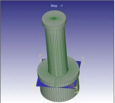
The application and subsequent modelling of punching processes with punching is done by modelling for cost reduction and a comprehensive study as well as experimental work as in other shaping processes. For this reason, the composition of the material used to create the material model, and tensile tests have been conducted with the Simufact program and compared with the experimental tensile test data. Verification of the material model is a very important factor for the precision of the punching process performed by computer. Then, 5 different punching operations were performed in 3-dimensional and 2-dimensional simulation under same boundary conditions and compared with experimental data. Experiments were done by
SIMUFACT and DEFORM finite element analysis programs. Figure 5.10. shows an example model created for the punching process obtained in DEFORM and SIMUFACT environment.
PART 5
EXPERIMENTAL RESULTS AND DISCUSSION
5.1. MATERIAL MODEL
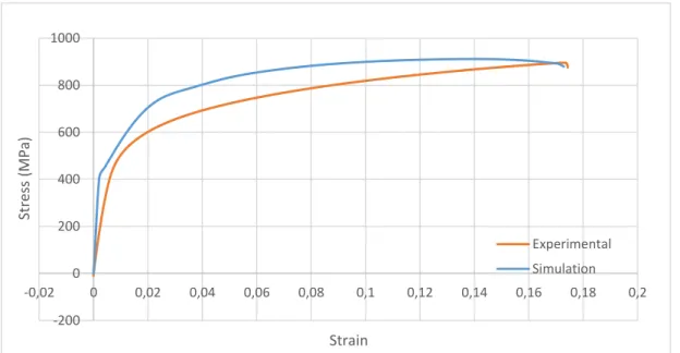
Tensile tests were applied to the material model with Simufact finite element software before punching experiments were done. In tensile tests, jaw speed was determined as 2 mm.min-1. Stress and strain graph results obtained because of experimental and simulation tests are shown in Figures 5.1 and 5.2. When comparing the graphs, there is a greater amount of strain in the experimental data, while it is thought that the significant difference in the elongation amount of the graph obtained by the finite element approach is because of the meshing process or the inability to model the existing flaws in the material. Besides that, it appears to have similar elongation and bearing load capacity.
Figure 5.1. Comparison of simulation and experimental data obtained from the tensile test of DP800 material. -200 0 200 400 600 800 1000 -0,02 0 0,02 0,04 0,06 0,08 0,1 0,12 0,14 0,16 0,18 0,2 Stres s (MPa) Strain Experimental Simulation
![Figure 1.1. Global formability diagram with position of advanced high strength steel [5]](https://thumb-eu.123doks.com/thumbv2/9libnet/5405763.102171/19.892.171.794.126.400/figure-global-formability-diagram-position-advanced-strength-steel.webp)
![Table 2.2. Reviews the product property requirements for many types of DP steels, according to ArcelorMittal standard 20×80 mm ISO tensile specimens (thickness: less than 3mm) [30]](https://thumb-eu.123doks.com/thumbv2/9libnet/5405763.102171/28.892.176.790.455.864/reviews-property-requirements-according-arcelormittal-standard-specimens-thickness.webp)

![Figure 2.5. Relationship between yield strength and total elongation for many types of steels [19, 38]](https://thumb-eu.123doks.com/thumbv2/9libnet/5405763.102171/33.892.274.684.222.451/figure-relationship-yield-strength-total-elongation-types-steels.webp)