Isı Bilimi ve Tekniği Dergisi, 40, 1, 141-153, 2020 J. of Thermal Science and Technology ©2020 TIBTD Printed in Turkey ISSN 1300-3615
THEORETICAL ANALYSIS OF A CASCADE REFRIGERATION SYSTEM WITH
NATURAL AND SYNTHETIC WORKING FLUID PAIRS FOR ULTRA LOW
TEMPERATURE APPLICATIONS
Barış YILMAZ*, Ebru MANÇUHAN** and Deniz YILMAZ***
*,**Marmara University, Faculty of Engineering, Mechanical Engineering Department
34722, Kadıköy, İstanbul, Turkey,
*[email protected] (corresponding author), **[email protected]
***İstanbul Arel University, Faculty of Engineering and Architecture, Mechanical Engineering Department 34295,
İstanbul, Turkey, [email protected] (Geliş Tarihi: 30.01.2019, Kabul Tarihi: 27.02.2020)
Abstract: In this study, a theoretical model is established using Engineering Equation Solver (EES) software in order
to investigate the effects of different design and operation parameters on the performance of the cascade systems for Ultra Low Temperature (ULT) between -50 oC and -100 oC. The analysis is performed for natural and synthetic
refrigerant pairs to find an environmentally friendly alternative to commercial synthetic refrigerants. Effects of common parameters such as the evaporation temperature of low temperature cycle (LTC), the condensation temperature of high temperature cycle (HTC) and the temperature difference in the cascade heat exchanger (HX) have been investigated with the proposed model. Furthermore, influence of operation parameters including vapor quality of the refrigerant after the expansion valve and the precooler heat exchanger (PCHX) capacity, crucial to reach ULT conditions, on the system performance are examined. This study also contributes to the theoretical evaluation of the feasible natural refrigerant alternatives for ULT applications and the comparison of these refrigerants with synthetic ones in terms of performance and the environmental aspects. It is found that the natural refrigerant R1270/R170 pair results in about 5% better COP and almost half less CO2 emissions compared to synthetic refrigerant R404A/R508B
pair.
Keywords: Ultra-Low Temperature, Cascade Refrigeration System, Natural Refrigerants, COP, TEWI
DOĞAL VE SENTETİK SOĞUTUCU AKIŞKAN ÇİFTLERİ KULLANILAN BİR
KASKAD SOĞUTMA SİSTEMİNİN ULTRA DÜŞÜK SICAKLIK UYGULAMALARI
İÇİN TEORİK ANALİZİ
Özet: Bu çalışmada, ultra düşük sıcaklık (UDS) (-50 oC ile -100 oC) uygulamalarında farklı dizayn ve çalışma
parametrelerinin kaskad sistem performansına etkilerini incelemek için EES yazılımı kullanılarak teorik bir model oluşturuldu. Kaskad sistemlerde kullanılan sentetik soğutucu akışkan çiftine çevre dostu bir alternatif bulmak için doğal ve sentetik soğutucu akışkan çiftleri için analiz yapıldı. Önerilen modelde; yüksek sıcaklık çevrimi (YSÇ) yoğuşma ve düşük sıcaklık çevrimi (DSÇ) buharlaşma sıcaklıkları ve kaskad ısı değiştiricisi sıcaklık farkı gibi parametrelerinin etkileri incelendi. Ayrıca, UDS uygulamalarında aşırı soğutma şartlarına ulaşabilmek için kritik çalışma parametreleri olan genleşme valfi sonrası soğutucu akışkanın buhar kalitesi ve ön soğutma amaçlı ısı değiştiricisi kapasitesinin sistem performansına etkileri incelendi. Bu çalışmada UDS uygulamalarında kullanılabilecek doğal akışkan alternatiflerinin performans ve çevresel etkileri açılarından teorik olarak karşılaştırılmalarına katkıda bulunulmaktadır. Yapılan analiz çalışmaları sonucunda soğutma sisteminde R1270/R170 doğal soğutucu çiftinin kullanılması ile, R404A/R508B sentetik soğutucu çiftine kıyasla %5 civarında daha iyi sistem performans katsayısı ve yaklaşık olarak yarısı kadar CO2
emisyon salımı gerçekleştiği belirlendi.
Anahtar Kelimeler: Ultra Düşük Sıcaklık, Kaskad Soğutma Sistemi, Doğal Akışkanlar, STK, TEWI NOMENCLATURE
Abbreviations
COP coefficient of performance
EES engineering equation solver
GWP global warming potential
h specific enthalpy [kJ kg-1]
HTC high temperature cycle
HX heat exchanger
IHX internal heat exchanger
LTC low temperature cycle
𝑚̇ mass flow rate [kg s-1]
NBP normal boiling point
ODP ozone depletion potential
P pressure
PCHX precooler heat exchanger
𝑄̇ heat transfer rate [kW]
T temperature [°C, K]
ΔT temperature difference
𝑊̇ power [kW]
Greek symbols
efficiencyα recycling factor (%)
β electrical regional conversion factor
(kg CO2/kWh) Subscripts C condensation CAS cascade Cond condenser Comp compressor CR critical DESUP desuperheating E electric Evap evaporator FR freezing HP high pressure
HTC high temperature cycle
in input
LP low pressure
LTC low temperature cycle
M mechanical out output p pump S isentropic SUB subcooling SUP superheating tot total INTRODUCTION
Refrigeration systems can be categorized depending on the evaporation temperature aimed to be achieved. The refrigeration processes performed between 50 °C and -100 °C are called Ultra Low Temperature (ULT) applications according to ASHRAE Handbook clasification (ASHRAE Handbook, 2010). The refrigeration systems operating at these temperature levels are mostly utilized for the storage of biological samples such as bacteria, bone marrow, cell cultures and DNA. Furthermore, these systems are used to liquify gases in petro chemistry industry. For many medical and industrial applications, the ULT refrigeration has not been accomplished efficiently in single-stage and multistage systems due to the limitations either in the thermo-physical properties of refrigerants or the cascade systems. The essential criteria of the systems operating at these low temperatures are specified in detail in ASHRAE Handbook, 2010.
Synthetic refrigerants consisting of Hydrofluorocarbons (HFCs) and Chlorofluorocarbons (CFCs) are chosen in most industrial refrigeration systems because of their superior cooling properties. In cascade systems, an appropriate selection of refrigerants to operate in the low and high temperature cycles should be made in order to obtain high COP. Generally, the synthetic refrigerants such as R404A, R507A, and R134a are used in HTC whereas the refrigerants such as R23 and R508B are used in LTC of systems in order to reach ULT levels. However, it is known that such compounds have adverse effects on ozone layer and thereby on environment. Recently, natural refrigerants started to be utilized for replacement of the synthetic ones. Among the natural fluids are water, carbon dioxide and various hydrocarbon compounds (propane, ethane, propylene, etc.) (Van Orshoven et al., 1993). Several organic fluids such as R23, R32, R125, R143a, R134a, R218, R170 and ammonia (R717) are also utilized as the working fluid of the power generation systems, especially for low grade energy source applications for instance Organic Rankine Cycle (ORC) (Vidhi et al., 2013; Vijayaraghavan et al., 2005). To achieve an environmentally friendly solution
in ULT applications, the natural refrigerants such as R290 (Propane), R1270 (Propylene) and R717 (Ammonia) may be chosen in HTC, and R170 (Ethane) or R1150 (Ethylene) may be selected in LTC. Moreover, the mixtures of different natural refrigerants can alternatively be used in LTC in order to achieve ULT levels such as nitrous oxide (N2O) alone and its mixture
with CO2 (Bhattacharyya et al. 2005; Syaka et al. 2011;
Bhattacharyya, et al. 2009; Nicola, et al. 2011; Gong et. al. 2009).
In literature, there are plenty of theoretical and experimental studies about cascade systems for low evaporation temperature of LTC between 30 °C and -50°C (Lee et al., 2006; Dopazo et al. 2009; Getu and Bansal, 2008; Messineo, 2012; Yılmaz et al., 2014; Bingming et al. 2009; Dopazo et al., 2011; Yılmaz et al. 2018). However, there are few theoretical studies investigating the effects of operation parameters on the COP for different refrigerant pairs in ULT applications. Sarkar et al. (2013), performed a theoretical analysis and optimization study to investigate the effects of operation parameters on the COP for ULTs between 85 °C and -55 °C. In that study; ethane, ethylene and nitrous oxide were used in HTC while the ammonia, propane and propene were used in LTC as working fluids in order to evaluate the refrigeration system performance. They concluded that the COP increased for ethane and ethylene whereas the COP decreased for N2O. Parekh and Tailor
(2011), developed a mathematical model of a cascade system using ozone-friendly refrigerants pair (R507/R23) in order to optimize the design and operating parameters. Model results showed that when the evaporation temperature was decreased from 50 °C to -80 °C and the overall COP reduced from 1.232 to 0.785. Consequently, they stated that the lowest value of evaporation temperature of LTC resulted in the lowest COP. Wadell (2005), analyzed experimentally a cascade system using R134a and R508B refrigerants in high temperature and low temperature cycles, respectively. In experiments, the evaporation temperature of LTC was varied from -86 °C to -79 °C and the studied mass flow rates of refrigerant were between 50-70 g/min. It was concluded that if the evaporator is designed as
microchannel and enhanced surface, better performances may be achieved. Kruse and Russmann (2006), analyzed and compared theoretically trans-critical CO2/N2O
system and R134a/R23 system. Their results showed that N2O is a good alternative refrigerant to R23 in LTC with
respect to the performance and the environmental trace. Utilization of R134a, R717 and hydrocarbons was proposed in HTC of the cascade system. They also concluded that trans-critical CO2/N2O system is more
sustainable solution instead of R717 and hydrocarbons. Kılıçaraslan et al. (2010), determined and compared the COP and irreversibility of the cascade system using a large family of environmentally friendly refrigerant pairs. They concluded that the cascade system’s COP increases and the irreversibility decreases with rising evaporation temperature of LTC for all selected refrigerant pairs. Mancuhan (2019) theoretically analyzed a refrigeration system with flash intercooling. Modeling of system was done by optimizing the intermediate pressure at given evaporation and condensation temperature values for all medium temperature application’s (R717, R134a and R152a) and low temperature application’s refrigerants (R290, R404A and R507A). Sun et al. (2019) evaluated the potential of refrigerant and found out which refrigerant couple performs better in cascade refrigeration system. In the considered 28 refrigerant pairs, R161 was suggested for use in HTC, and R41 and R170 were suggested for use in LTC. Babiloni et al. (2019) presented a comprehensive review on available literature on ULT applications. They concluded that the current status of the technology offers the most promising low GWP alternatives, although the existing regulations do not limit high GWP refrigerants used in ULT applications.
The present study proposes a mathematical model for a cascade ULT application with an Internal Heat Exchanger and a precooler heat exchanger in LTC side to determine the optimum design and operating parameters and produce the data for the future experimental applications. Earlier works are mainly focused on the theoretical and experimental analysis of cascade systems operating at evaporation temperatures of LTC between -30 oC and -50 oC (Lee et al., 2006; Dopazo
et al. 2009; Getu and Bansal, 2008; Messineo, 2012; Yılmaz et al., 2014; Bingming et al. 2009; Dopazo et al., 2011; Yılmaz et al. 2018). There are limited number of theoretical studies about cascade ULT system in literature. In addition, no study is found on two crucial operation parameters; vapor quality of the refrigerant after the expansion valve of the LTC and the PCHX capacity. These parameters are critical for the LTC subcooling processes which are required to reach ULT levels and affect significantly the system COP. The key contributions of this work can be summarized as follow; performing the theoretical analysis of a unique cascade system operating at ultra-low temperature conditions between -50 oC and -100 oC and evaluating the feasible
natural refrigerant alternatives in terms of the increasing the cascade system performance and decreasing the harmful environmental effects.
BACKGROUND
Physical and Environmental Evaluations of Refrigerants
The most conveinent refrigerant in a refrigeration application can be decided based on its important characteristics such as Ozone Depletion Potential (ODP), Global Warming Potential (GWP), toxicity, flammability etc. along with the operating and design conditions. Additionally, Total Equivalent Warming Impact (TEWI), a measure of the trace of refrigerants on the environment including both the direct and indirect global warming effects of the refrigeration systems, is calculated. The direct effect represents the release of refrigerant directly to the atmosphere. On the other hand, the indirect effect corresponds to the CO2 emissions due to fossil fuel
consumption for energy production to drive the refrigeration system during its life time. TEWI comparison performed using the following correlation proposed by AIRAH (2012), provides a detailed environmental evaluation of the system.
𝑇𝐸𝑊𝐼 = GWPref(m𝑟𝑒𝑓× Lannual× N + m𝑟𝑒𝑓×
(1−∝)) + (Eannual× β × N) (1)
where N is the system lifetime (year) , mref is the total
refrigerantcharge (kg), Lannual is the refrigerant leakage
rate (%), α is the recycling factor, Eannual is energy
consumed per year (kWh/year) and β is the electricity regional conversion factor (kgCO2/kWh).
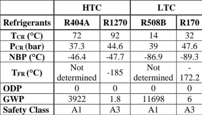
The physical and environmental properties of refrigerants that are subject of this study are given in Table 1. In this study, one natural and one synthetic refrigerant pairs are used. As the synthetic refrigerant pair, R404A/R508B is chosen . R404A has the evaporation temperature about -40 °C without falling into vacuum pressure. Therefore, it can be used HTC refrigerant in cascade systems. R508B has a very low boiling point of -86.9 oC at 1 atm. Therefore, it can be used LTC
refrigerant in ultra-low refrigeration system as these systems operate at just above R508B’s boiling point. R508B is also non-toxic and non-flammable. On the other hand, R1270/R170 with negligible GWP offers a natural alternative solution pair for ultra-low refrigeration systems. In a cascade refrigeration system, R1270 is utilized in HTC and R170 is used in LTC. However, they have a safety rating of A3 which shows highly flammable property according to ASHRAE Standard 34 (2016). Hence, using R1270 and R170 requires additional safety measures.
Ultra-low Temperature Refrigeration Systems
Operating at ultralow temperature levels,i.e. between -50 °C and -100 °C, with a single-stage system is difficult to reach since the parameters such as compression ratio, ambient air temperature and refrigerant properties limit
the system operation. The lowest temperature level that can be reached with single-stage refrigeration system is around -40 °C to -45 °C in industrial applications. On the other hand, two-stage cascade systems do not have this limitation as they can efficiently achieve the ULTs between -45 °C and -80 °C.
Table 1. The physical and environmental properties of refrigerants used in this study (IPCC, Climate Change, 2013)
HTC LTC Refrigerants R404A R1270 R508B R170 TCR (°C) 72 92 14 32 PCR (bar) 37.3 44.6 39 47.6 NBP (°C) -46.4 -47.7 -86.9 -89.3 TFR (°C) Not determined -185 Not determined -172.2 ODP 0 0 0 0 GWP 3922 1.8 11698 6 Safety Class A1 A3 A1 A3
The schematic diagram of the proposed ULT cascade refrigeration system consisting of high and low temperature cycles is shown in Figure 1. Main components of the HTC are two compressors, an air-cooled condenser, an internal heat exchanger, a primary expansion valve and a secondary expansion valve. HTC compressors are operated between two pressure levels. Low and high pressure compressors sustain a reliable operation if the difference between the evaporation and the condensation pressures is high. An internal heat exchanger of HTC (IHXHTC) provides subcooling effect
before entering the primary expansion valve between state 8 and state 11 and protects the compressor from two phase flow as shown in Figure 1. Meanwhile, low quality vapor exits from the secondary expansion valve (state 9) and becomes saturated vapor at state 10. A cascade HX is located between the high and low temperature cycles. In the cascade HX, the refrigerant in the LTC cycle is condensed whereas the liquid phase refrigerant evaporates in the HTC cycle.
The components of the LTC are shown in Figure 1 which are a compressor, an expansion valve, an evaporator, an IHXLTC and a PCHX. The IHXLTC functions as a
subcooler and a suction gas heater for compressor of LTC. Therefore, it subcools the refrigerant at the outlet of cascade HX and superheats the refrigerant at the inlet of the compressor. Thus, a more reliable operation for the LTC compressor is achieved. Moreover, the desuperheating of the refrigerant is essential since the exit temperature of LTC compressor is relatively higher than the conventional ULT applications. Minh et al. (2006), stated that utilizing the IHXLTC for subcooling
helps to protect the compressor from two-phase flow and provides the low quality of refrigerant entering the evaporator so that it improves the system COP. Desuperheating of the refrigerant is provided by a PCHX located before the cascade HX. The PCHX is assumed to be a water pumped cyle having inlet and outlet temperatures of 10 oC and 35 oC, respectively. It lowers
the LTC refrigerant's temperature to 55 K higher than TCAS,E.
The desuperheating degree (ΔTDESUP=T1-T1a) is defined
as the difference between the exit temperature of compressor (T1) and inlet temperature of the cascade
condenser (T1a). The subcooling and desuperheating
processes let the theoretical model can be applied to the real applications. Figure 2 presents the pressure-enthalpy diagram corresponding to the investigated cascade system.
Figure 1. Schematic view of a cascade refrigeration system Thermodynamic Analysis
The mathematical model of the cascade refrigeration system is developed based on energy and mass conservation equations. Expressions are obtained for each components of both high and low temperature cycles.
The developed model of the system is implemented to the Engineering Equation Solver (EES) software (Klein, 2017). EES software having a high accuracy thermodynamic database involving many of pure substances and mixtures is commonly used for thermodynamic analysis of the cyclic devices.
Figure 2. P-h diagrams of the investigated cascade system; for a) LTC, b) HTC
In our system analysis, the following assumptions are taken into account:
Heat transfer in heat exchangers is performed as isobaric process.
Refrigerants are expanded with constant enthalpy (isenthalpic) in expansion valves.
Pressure drops in the system pipes and heat exchangers are neglected.
The change in potential and kinetic energy is neglected.
In Table 2, we set the variable operating and constant design parameters for our system. In most of the applications, the cascade HX is designed to have 60 K difference, as in the industrial applications, between the TCAS,E and the refrigerant outlet temperature from the
PCHX (T1a). Therefore, the maximum temperature
difference between the TCAS, E and T1a is assumed to be
constant at 55 K as in the reference (SWEP Company, 2016).
The subcooling degree of LTC (ΔTSUB_LTC) is determined
depending on the following constraints:
The vapor quality after the expansion valve should not be lower than 0.10 (Cengel and Boles, 2007) so that it is chosen to be 0.15.
While the liquid at the cascade condenser outlet (State 2) is cooled, the vapor at the LTC compressor inlet (State 6) is heated by IHXLTC utilization. If the suction
gas temperature of the compressor (State 6) gets higher, the discharge temperature (State1) and the desuperheating requirement increases. To prevent the increase in desuperheating, the LTC refrigerant is cooled by a PCHX. The PCHX is chosen to be a water pumped cyle working between 10 °C and 35 °C. The maximum desuperheating capacity of the PCHX is chosen to be 6 kW as a design condition.
Table 2. Design and operating parameters used in the model Design parameters
Compressor isentropic efficiency(𝜂𝑆)
(Brunin et al.,1997)
𝜂𝑆= 0.874 − 0.0135 𝑃𝐻 𝑃𝐿
Mechanical efficiency (𝜂𝑀) (Brunin et al.,1997) 𝜂𝑀 = 0.959 − 0.00642𝑃𝐻
𝑃𝐿
Compressor electric motor efficiency(𝜂𝐸) (Brunin et al.,1997) 0.90
Compressor Overall Effciency(𝜂𝐶) 𝜂𝐶= 𝜂𝑆𝜂𝑀𝜂𝐸
Effectiveness of cascade HX 1.0
System refrigeration capacity (QEVAP) kW 11
The temperature difference between TE and TSpace K 6
The temperature difference in cascade HX (∆TCAS) K 8
The maximum temperature difference between the TCAS, E and T1a
(SWEP Company, 2016)
K 55
Superheating in LTC evaporator K 6
Superheating in evaporator side of cascade HX K 5
Operating Parameters
LTC evaporation temperature range (TE) °C -60 to -86
HTC condensation temperature (TC) °C 30 to 55
The evaporation temperature of cascade HX (TCAS, E) °C -40 to -20
The minimum vapor quality after the expansion valve - 0.15
The maximum desuperheating capacity of PCHX kW 6
(a)
Power consumption of water pump is assumed to be negligible.
The temperature values of State 11 and State 9 of HTC are set to 8.67 °C and -5 °C, respectively. These values are determined based on the compressor catalog data (GEA Germany, 2016).
Model equations
The cascade system is modelled using Thermodynamics laws. The derived mass and energy equations are presented below for each component of the system. The corresponding schematics and diagrams are given in Figures 1 and 2.
Compressor power consumption of LTC is defined as: ẆLTC= ṁLTC_in(h1− h6) (1)
where the mass flow rate of compressor inlet is
ṁLTC_in= ṁ6 (2)
Total compressor power consumption of HTC is given as:
ẆHTC= ṁHTCLP,in(h14− h13) + ṁHTCHP,in(h7− h15)
(3) where the mass flow rates inlet to the low pressure and high pressure compressors of HTC are as follows;
ṁHTCLP,in= ṁ13 (4)
ṁHTCHP,in= ṁ15= ṁ10+ ṁ14 (5)
Total refrigerant mass flow rate of HTC is
ṁHTCTotal= ṁHTCHP,in (6)
The rate of heat is rejected by the condenser of HTC is calculated as:
Q̇HTC_Cond= ṁHTC,Total(h8− h7) (7)
The heat transfer rate into the cascade HX is defined as: Q̇CAS= ṁHTCLP,in(h13− h12) = ṁLTC,in(h1a− h2)
(8) The refrigeration capacity of LTC evaporator is determined as:
Q̇LTC_Evap= ṁLTC,in(h5− h4) (9)
The heat transfer rate into the IHXof HTC and IHXof LTC are, respectively:
ṁHTCLP,in(h8− h11) = (ṁHTC− ṁHTCLP)(h10− h9)
(10)
ṁLTC,in(h2− h3) = ṁLTC,in(h6− h5) (11)
Energy balance for the adiabatic mixing process between the low pressure and the high pressure compressors of HTC:
ṁHTCLP,inh14+ (ṁHTC− ṁHTCLP)h10= ṁHTC,inh15
(12) Desuperheating capacity of the PCHX of LTC can be defined as:
Q̇PC_HX= ṁLTC,in(h1− h1a) (13)
And finally, the overall COP of the cascade system is determined by:
COP = Q̇LTC_Evap
ẆLTC+ẆHTC (14)
RESULTS AND DISCUSSION
The synthetic refrigerant pair of R404A/R508B is reliable choice to be used in ULT operations in a cascade system. However, these refrigerants are not environmentally friendly because of their high GWPs. A natural refrigerant alternative couple may be R1270/R170 having negligible GWPs and satisfactory operation performance for ultra-low applications. In practice, additional safety measures are required for this refrigerant pair since they are highly flammable. If the safety measures are taken in place, R1270/R170 is a convenient alternative. However, the performance of proposed refrigerant pair should be examined in detail and compared with the real applications.
A cascade system using both R404A/R508B and R1270/R170 refrigerant pairs is examined theoretically in order to determine the effects of design and operating parameters for ULT conditions. The mathematical models have been developed and implemented in EES for evaluation. The modelling results include the analysis of operating parameters as in the literature which are TE,
TC, subcooling and superheating temperatures of LTC,
temperature difference (ΔTCAS) in the cascade HX,
subcooling and superheating temperatures of HTC (Lee et al., 2006; Dopazo, et al. 2009; Getu, et al. 2008; Yılmaz et al. 2014; Sarkar et al., 2013; Parekh and Tailor; 2011). In addition, the operation parameters such as; the refrigerant vapor quality after the expansion valve of LTC and the PCHX capacity which are crucial to determine the LTC subcooling level and system COP are also considered.
Investigation of Subcooling Degree in LTC
In literature, it is reported that subcooling increases COP whereas superheating decreases it. Therefore, subcooling level should be set as high as possible and superheating value should be set as low as possible. Parekh and Tailor (2011) showed this effect through their cascade system
model. They were determined that increasing the subcooling degree in both LTC and HTC resulted in the increase of the COP. Therefore, the precise determination of the LTC subcooling degree is critical to calculate the maximum overall COP.
The vapor quality at the expansion valve exit is suggested to be selected between 0.10 and 0.20 in the thermodynamics modelling studies of cascade systems (Cengel and Boles, 2007). In this study, the minimum vapor quality of refrigerant is set to the average of the range (0.15). On the other hand, by the utilization of IHXLTC, the condensed refrigerant from the cascade
condenser is subcooled while the saturated refrigerant vapor in evaporator of LTC is superheated. If the refrigerant is too much superheated before entering the compressor, the outlet temperature of the compressor will also increase. This causes a very high desuperheating necessity and requires high capacity of PCHX. The maximum capacity of PCHX is assumed to be 6 kW as a constraint in the present study.
The design and operating parameters are shown for both refrigerant pairs R404A/R508B and R1270/R170 in Table 3 and Table 4, respectively. The corresponding performance results are calculated using the mathematical model equations of the system. In Table 3, two cases of the synthetic refrigerant pair are presented to investigate the performance of the system.
In the first case, the vapor quality after the expansion valve (which is a constraint parameter for the system design) is kept constant at 0.15 while the TCAS,E is
changed from -40 °C to -35 °C. The highest overall COP is calculated to be 0.73 when the subcooling degree, the capacity of PCHX and the desuperheating degree are set to 33.2 K, 5.42 kW and 76.3 K, respectively. When the
TCAS,E decreases from -35 oC to -40 oC COP decreases
from 0.73 to 0.71 correspondingly.
In the second case, the total capacity of PCHX is kept constant at 6 kW while TCAS,E varies from-30 oC to -20 oC. The highest overall COP is calculated to be 0.72 when
the subcooling level, the vapor quality after expansion valve and the desuperheating are selected to be 31 K, 0.22 and 77.1 K, respectively. Decreasing TCAS,E within given
range increases the COP from 0.63 to 0.72 as seen in Table 3.
In Table 4, similarly, two cases are investigated for the natural pair of refrigerants. In the first case, the vapor quality is kept constant at 0.15 as in the synthetic option.The TCAS,E is varied from -40 °C to -35 °C. The
highest overall COP is found to be 0.77 when the subcooling degree, the PCHX capacity and the desuperheating degree are set to 33.2 K, 5.92 kW and 107.3 K, respectively. It is found that the COP decreases slightly from 0.77 to 0.76. In the second case, the PCHX capacity is kept constant at 6 kW similarly while the TCAS,E varies from-30 oC to -20 oC. The highest overall
COP is calculated to be 0.76 when the subcooling amount is selected as 31.0 K, the vapor quality after expansion valve is 0.17 and the desuperheating level is 108.9 K. In this case, the TCAS,E decreases from -20 oC to -30 oC and
COP increases from 0.70 to 0.76.
Parekh and Tailor (2011) indicated that COP value might be lower than 1 since the difference between TE and TC is
very high in the ultra-low operational temperatures. From the calculated values given in Table 3 and Table 4, R1270/R170 is found to be a better alternative of R404A/R508B with respect to COP and low environmental trace for ULT conditions.
Table 3. Modeling results of the cascade system with R404A/R508B HTC TCAS,E (°C) LTC TCAS,C (°C) LTC ΔTSUB (K) Exp.Valve inlet,T3 (°C) Vapor quality x4 QPCHX (kW) QIHX (kW) COP LTC ΔTDESUP (K) -40 -32 27.9 -59.9 0.15 4.28 2.77 0.71 61.6 -35 -27 33.2 -60.2 0.15 5.42 3.35 0.73 76.3 -30 -22 31.0 -53.0 0.22 6.00 3.46 0.72 77.1 -25 -17 24.8 -41.8 0.30 6.00 3.25 0.68 68.9 -20 -12 17.9 -29.9 0.40 6.00 2.86 0.63 57.5
Table 4. Modeling results of the cascade system with R1270/R170 HTC TCAS,E (°C) LTC TCAS,C (°C) LTC ΔTSUB (K) Exp. Valve inlet,T3 (°C) Vapor quality x4 QPCHX (kW) QIHX (kW) COP LTC ΔTDESUP (K) -40 -32 27.9 -59.9 0.15 4.90 2.02 0.76 91.3 -35 -27 33.2 -60.2 0.15 5.92 2.43 0.77 107.3 -30 -22 31.0 -53.0 0.17 6.00 2.43 0.76 108.9 -25 -17 24.8 -41.8 0.24 6.00 2.16 0.74 101.8 -20 -12 17.9 -29.9 0.30 6.00 1.79 0.70 92.1
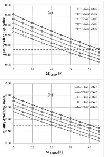
The constant vapor quality
Figure 3 (a) and (b) illustrate that increasing the subcooling level from 5 oC to 50 oC reduces the vapor
quality after expansion valve when TCAS,E changes
between -40 oC and -20 oC. The vapor quality after the
LTC expansion valve is examined with respect to desired value of 0.15. The vapor quality value intersects with various TCAS,E values. The LTC operating conditions
such as subcooling degree are determined for several temperatures by using these intersection points. It is found that the subcooling degree of LTC (ΔTSUB) varies
between 30 oC and 50 oC for R404A/R508B system, on
the other hand, ΔTSUB changes between 25 oC and 45 oC
for R1270/R170 system for the reliable operation of the cascade system.
The constant PCHX capacity
Subcooling process has to be applied after the cascade HX to reach design evaporation level of TE (-86 oC).
Subcooling degree can be defined as temperature difference between state 2 and state 3 (ΔTSUB_LTC = T2
-T3). It is accomplished by an IHXLTC located before the
expansion valve.
Figure 3. Effect of subcooling of LTC on vapor quality after expansion valve for different TCAS,E (a) R404A/R508B (b)
R1270/R170 .
The utilization of IHXLTC both subcools the refrigerant at
the outlet of cascade HX and superheats the refrigerant at the inlet of the compressor as mentioned before. Therefore, the necessary capacity of the PCHX is one of the operation parameters. Another operation parameter is the difference between TCAS,E and the refrigerant exit
temperature (T1a) from the PCHX. The maximum
temperature difference between T1b and TCAS, E is
assumed to be constant at 55 K as in the real applications (SWEP Company, 2016). When TCAS,E is chosen to be
-40oC, the lowest value of T
1a should be 15 oC, if the 6 kW
PCHX capacity is considered. The high values of T1 and
T6 indicate the high subcooling necessity in IHXLTC.
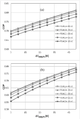
Figure 4 (a) and (b) display that increasing the subcooling level from 5 oC to 50 oC rises the PCHX capacity while
TCAS,E changes between -40 oC and -20 oC. The PCHX
capacity is chosen to be 6 kW as the desired condition. The PCHX capacity value intersects with various TCAS,E
lines so that intersection points correspond to the desired LTC operating conditions such as subcooling degree. The ΔTSUB is found between 18 oC and 50 oC for
R404A/R508B system whereas the ΔTSUB is obtained
between 14 oC and 45 oC for R1270/R170 system.
However, the vapor quality after expansion valve is set to the maximum possible value of 0.20.
Figure 4.Effect of subcooling of LTC on PCHX capacity for different TCAS,E for (a) R404A/R508B (b) R1270/R170 .
(a)
(b)
(a)
Effect of LTC Subcooling Degree on COP
In Figure 5 (a) and (b), it is observed that increasing the subcooling level from 5 oC to 50 oC promotes the COP for
all TCAS,E conditions. In addition, the COP of both systems
increases for all values of the LTC subcooling degree while the TCAS,E is decreased from -20 oC to -35 oC.
In this case study, the TE is kept constant at -86 oC for
ULT operation. Decreasing TE value decreases also the
TCAS,E in general. From the calculation results of model
equations, it is concluded that the lower value of TCAS,E
affects the system COP positively. As a result, the highest COP is calculated (0.73) for the subcooling degree of 33.2 oC at R404A/R508B system along with the selected
TCAS,E at -35 oC. Likewise, the highest COP is calculated
(0.77) for the subcooling degree about 33.2 oC for
R1270/R170 system when TCAS,E is -35 oC.
Figure 5.Effect of subcooling of LTC on COP for different evaporation temperature of HTC (TCAS,E) for (a) R404A/R508B
(b) R1270/R170.
Effect of Evaporation Temperatures of LTC and HTC on the COP
The effect of the operating parameters; TE of LTC and
TCAS,E of HTC on the COP is investigated and compared
for two refrigerant pairs.
Figure 6 shows that increasing TE of LTC results in the
increase of COP for both R404A/R508B and
R1270/R170 systems. It is also found that the natural refrigerant pair R1270/R170 results in higher COP than the synthetic refrigerant pair R404A/R508B for all TE
values between -61 oC and -86 oC. In Figure 7, varying
the TCAS,E between -40 oC and -20 oC shows a maximum
value of COP about -35 oC for both refrigerant pairs.
Figure 6. Effect of the LTC side TE of on COP
Figure 7. Effect of TCAS,E on COP
Effect of HTC Condensation Temperature (TC) of
HTC on COP
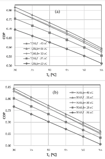
In Figure 8 (a) and (b), it is seen that increasing the TC
from 30 oC to 55 oC, representing the effect of the
ambient conditions, reduces the COP values for all TCAS,E
values of HTC.
It is observed that the R1270/R170 pair has relatively higher COP values compared to the R404A/R508B pair for all TC and TCAS,E. In addition, it is seen that the
increase of the condensation temperature results in decrease in COP for both cases. However, the difference is found higher for R404A/R508B pair.
Impact of the Cascade Refrigerant Pairs on the Environment.
In this section, the effect of using different refrigerant pairs on the system performance and the environment has been examined. Furthermore, TEWI values of two (a)
refrigerant options, R404A/R508B (System 1) and R1270/R170 (System 2), have been investigated for the leakage of the refrigerants to the atmosphere. In this case study, TC, TE and TCAS,E are chosen to be 40 oC, -86 oC, and
Figure 8. Effect of HTC condensation temperature (TC) of on
COP for different evaporation temperature of HTC (TCAS,E) for
(a) R404A/R508B (b) R1270/R170.
-35 oC, respectively. The ΔT
CAS is assumed to be constant
at 8 K, ΔTSUB is 30 oC and ΔTSUP of LTC is 20 oC.
The TEWI analysis assumptions are summarized in Table 5. The correcponding values of the parameters used in Eq. 1 are also listed in the table. The mass flow rate requirements for different refrigerants are initially calculated. Then the total GWP values of each refrigerant is obtained. For the chosen refrigeration capacity of 11 kW, mass flow rates of System 1 refrigerants are found as 0.14 kg/s for R404A and 0.08 kg/s for R508B. On the other hand, the mass flow rates of System 2 refrigerants are calculated as 0.05 kg/s for R1270 and 0.03 kg/s for R170. The amount of the refrigerant charge is estimated according to receiver’s volume (Sınar, 2018). In addition, the compressor power consumptions of of System 1 and 2 are given in Table 6.
TEWI analysis plays an important role in the selection of environmentally friendly refrigerant pair of the systems. For comparison between the Systems 1 and 2, the TEWI values are calculated using Equation (1) and the COPmax
of systems are presented in Table 6.
Table 5. TEWI analysis assumptions (AIRAH, 2012)
mRef* (kg) 𝑚𝑅𝑒𝑓= 𝑚̇𝑅𝑒𝑓 𝑥240
Lannual (%) 12.5
N (year) 15
Α (%) 0.7
β* (kgCO2/kWh) 0.65
Operation time (h/year) 6570
GWPRef 𝐺𝑊𝑃𝑅404𝐴= 3922
𝐺𝑊𝑃𝑅508𝐵 = 11698
𝐺𝑊𝑃𝑅1270= 1.8
𝐺𝑊𝑃𝑅170= 6
*(Sınar, 2018),**(Horton, 2002)
Table 6. Comparison of TEWI and COPmax values for Systems 1 and 2
Systems 1 (R404A/R508B) Systems 2 (R1270/R170) Refrigerant charge (kg) 33.6 19.92 12 7.2
Refrigerant leakage rate (%/year) 0.125 0.125 0.125 0.125
Service life (years) 15 15 15 15
Recycling factor 0.7 0.7 0.7 0.7
GWP 3922 11698 1.8 6
Direct CO2 emission of refrigerants (kg CO2) 286,620 506,828 46.98 93.96
Total direct CO2 emission of refrigerants (kg CO2) 793,447.31 140.94
Power consumption (kW) 8.71 6.96 7.81 7.09
Operation (h/year) 6570 6570
Service life (year) 15 15
CO2 emission factor 0.65 0.65
Indirect CO2 emission (kg CO2) 1,003,781.0 954,456.8
TEWI equivalent CO2 emission (kg CO2) 1,797,228.3 954,597.7
COPmax 0.73 0.77
(a)
It is found that System 1 with a synthetic refrigerant pair emits considerably higher amounts of greenhouse gases than System 2 during their lifetime. According to the TEWI values, high GWP of System 1 shows the higher contribution to the direct CO2 emission. On the
other hand, the indirect part of TEWI values are found almost the same for both systems. When the total TEWI levels are compared, System1 shows almost twice more emissions compared to System 2. It is concluded that as well as the natural refrigerant alternative has higher COP (0.77) it also results in the better environmental performance compared to its synthetic counterpart.
CONCLUSIONS
This study evaluates two types of refrigerant pairs,
namely R404A/R508B and R1270/R170,
corresponding to the synthetic and natural refrigerant options in terms of performance and environmental considerations for a ULT cascade refrigeration system. It is found that the COP of the natural refrigerant pair, R1270/R170, is calculated slightly higher (0.77) than that of the R404A/R508B case (0.73). Futhermore, the TEWI value of the natural refrigerant pair is approximately half of the that of the synthetic refrigerant pair. Thus, R1270/R170 is the better environmentally friendly candidate at ULT applications with higher COP performance.
The proposed ULT cascade system using both refrigerant alternatives, R404A/R508B and R1270/R170, are extensively investigated in order to determine the effects of design and operating parameters on the COP. The following outcomes are obtained from the study:
The vapor quality after expansion valve is set to 0.15 as the first constraint while the effect of TCAS,E
has been evaluated at various temperatures from -40 oC to -20 oC for both refrigerant alternatives. The
best COP value is obtained for the TCAS,E value of
-35 oC and the optimum ΔT
SUB is found to be 33.2 oC for both R404A/R508B and R1270/R170 cases.
The COP values are found 0.77 and 0.73 for the natural and the syntetic refrigerant pairs, respectively.
The PCHX capacity is selected to be 6 kW as the second constraint. The vapor quality after expansion valve is considered to be less than 0.20. In this case, R404A/R508B refrigerant pair satisfies this constraint for TCAS,E at -35 oC and the
subcooling degree of LTC at 33.2 oC. On the other
hand, R1270/R170 alternative satisfies the design condition at most -30 oC and 31 oC for the T
CAS, E
and ΔTSUB of LTC, respectively. The replacement
of synthetic refrigerant pair with natural refrigerant improves efficiency about 5%.
It is observed that increasing the TE results in the
increase of COP for both types of refrigerant pairs as expected. The natural refrigerant case results in the higher COP than the synthetic solution for all
evaporation temperatures of LTC between -86 oC
and -60 oC.
Increasing TCAS, E up to about -35 oC increases the
COP. For lower values of the TCAS,E, less than -35 oC, the COP value decreases. However, it is also
revealed that the COP values of the natural refrigerant option are higher than those of the synthetic refrigerant option when the TCAS, E is
varied between -40 oC and -20 oC.
It is found that increasing the TC from 30 oC to 55 oC reduces the COP values for all T
CAS, E. It is also
observed that the natural refrigerant option has relatively higher COP values compared to the synthetic refrigerant option for all condensation and evaporation temperatures of HTC.
The environmental trace of both refrigerant options are also evaluated for the leakage of refrigerants scenario in terms of TEWI values. It is found that the system with synthetic refrigerant option causes almost twice more CO2 emmissions than the natural
option.
REFERENCES
AIRAH, Methods of Calculating Total Equivalent Warming Impact (TEWI) 2012, Best Practice Guidelines. The Australian Institute of Refrigeration, Air Conditioning and Heating
ASHRAE, 2016, “Designation and Safety Classification of Refrigerants,” ANSI/ASHRAE, Atlanta, GA, Standard No. 34.
ASHRAE Handbook–Refrigeration, 2010, “American Society of Heating, Refrigerating and Air-Conditioning Engineers, Inc.”, (SI Edition).
ASHRAE, 2000, “Standard Method of Testing Forced Circulation Air Cooling and Air Heating Coils,” ANSI/ASHRAE, Atlanta, GA, Standard No. 33. Babiloni, A.M., Joybari, M.M., Esbri, J.N., Cervera, A.B., Albuixech, M.A., Moles, M., 2019, Ultralow-temperature refrigeration systems:Configurations and refrigerants to reduce the enviromental impact, International Journal of Refrigeration, doi:https://doi.org/10.1016/j-ijrefrig.2019.11.016 Bhattacharyya, S., Mukhopadhyay, S., Kumar, A., Khurana, R.K. and Sarkar, J., 2005, “Optimization of a CO2-C3H8 Cascade System for Refrigeration and
Heating,” Int. J. of Refrigeration, 8, pp. 1284–1292. Bhattacharyya, S., Garai, A., and Sarkar, J., 2009, “Thermodynamic Analysis and Optimization of a Novel N2O-CO2 Cascade System for Refrigeration and
Heating,” Int. J. of Refrigeration, 32, pp.1077–1084. Bingming, W., Huagen, W., Jianfeng, L., and Ziwen, X., 2009, “Experimental Investigation on the Performance of NH3/CO2 Cascade Refrigeration
System with Twin-screw Compressor,” Int. J. of Refrigeration, 32, pp.1358–1365.
Brunin, O., Feidt, M., Hivet, B., (1997), Comparison of the working domains of some compression heat pumps and a compression-absorption heat pump, International Journal of Refrigeration, 20-5, 308-318. Cengel, Y. A., and Boles, M. A., 2007,
“Thermodynamics: An Engineering Approach”, Sixth ed. McGraw-Hill, Singapore
Dopazo, J.A., Seara, J. F., Sieres, J., and Uhia, F.J., 2009, “Theoretical Analysis of a CO2-NH3 Cascade
Refrigeration System for Cooling Applications at Low Temperatures,” Appl. Therm. Eng., 29(8-9) pp.1577-1583.
Dopazo, J. A., and Seara, J.F. 2011, “Experimental Evaluation of a Cascade Refrigeration System Prototype with CO2 and NH3 for Freezing Process
Applications,” Int. J. of Refrigeration, 34, pp. 257-267. GEA Germany 2016,
https://vap.gea.com/stationaryapplication/Pages/Produ ct.aspx?ItemObjectID=TS&Size=HGZX7&ProductID =2039
Getu, H., and Bansal, P., 2008, “Thermodynamic Analysis of an R744-R717 Cascade Refrigeration System,” Int. J. of Refrigeration, 31(1), pp.45–54. Gong, M., Zhaohu, S., Jianfeng, W., Zhang, Y., Meng, C., and Zhou, Y. 2009, “Performance of R170 Mixtures as Refrigerants for Refrigeration at -80°C Temperature Range,” Int. J. of Refrigeration, 32, pp. 892-900. Horton, W.T., Modelling of secondary loop refrigeration systems in supermarket applications, Purdue University, PhD thesis, 2002.
IPCC. Climate Change 2013: The Physical Science Basis, Cambridge University Press, Cambridge, United Kingdom and New York, USA, 2013.
JP 5 B-A-CVBP - Grundfos Product Center, 2016, https://product selection.grundfos.com/product-detail (Accessed 24 December 2016)
Kilicarslan, A., and Hosoz, M., 2010, “Energy and Irreversibility Analysis of a Cascade Refrigeration System for Various Refrigerant Couples,” Energy Convers. Manag., 51 (12), pp.2947-2954.
Klein, S.A., 2017, “Engineering Equation Solver (EES)”, Academic Professional V10.294, F-Chart Software, Madison, WI, USA.
Kruse, H., and Russmann, H., 2006, “The Natural Fluid Nitrous oxide-An option as Substitute for Low Temperature Synthetic Refrigerants,” Int. J. of Refrigeration 29 (5), 799-806.
Lee, T., S., Liu, C., H., and Chen, T., W., 2006, “Thermodynamic Analysis of Optimal Condensing Temperature of Cascade-condenser in CO2/NH3
Cascade Refrigeration Systems,” Int. J. of Refrigeration, 29 (7), pp. 1100–1108.
Mancuhan, E., 2019, “A comprehensive comparison between low and medium temperature application refrigerants at a two-stage refrigeration system with flash intercooling,” Thermal Science and Engineering
Progress, 13,
https://doi.org/10.1016/j.tsep.2019.100357.
Messineo, A., 2012, “R744-R717 Cascade Refrigeration System: Performance Evaluation Compared with a HFC Two-stage System,” Energy Procedia, 14, pp.56-65.
Minh, N., Q., Hewitt, N., J., and Eames, P. C., 2006, “Improved Vapor Compression Refrigeration Cycles: Literature Review and Their Application to Heat Pumps,” International Refrigeration and Air Conditioning Conference, Purdue, USA.
Nicola, D. G., Polonara, F., Stryjek, R., and Arteconi, A., 2011, “Performance of Cascade Cycles Working with Blends of CO2+Natural Refrigerants,” Int. J. of
Refrigeration, 34, pp. 1436-1445.
Parekh, A. D., and Tailor, P.R., 2011, “Thermodynamic Analysis of R507A-R23 Cascade Refrigeration System”, Int. J. of Mechanical and Mechatronics Eng., 5 (9), pp. 1919-1923.
Sarkar, J., Bhattacharyya, S., and Lal, A., 2013, “Performance Comparison of Natural Refrigerants Based Cascade Systems for ULT Applications,” Int. J. of Sustainable Energy, 32(5), pp. 406-420.
Sınar, U., Numerical analysis of a cascade refrigeration system operating at ultra-low temperatures, Marmara University, Master’s Thesis, 2018.
Sun, Z., Wang, Q., Xie, Z., Liu, S., Su, D., Cui, Q., 2019, Energy and axergy analysis of Low GWP refrigerants in cascade refrigeration system, Energy, 170, 1170-1180
SWEP Company 2016,
http://www.swep.cn/refrigerant-handbook/10.-systems/asdf2/
Syaka, N. D. R. B., and Alhamid, M. I., 2011, “Cascade Refrigeration System Using Mixture of Carbon dioxide
and Hydrocarbons for Low Temperature
Applications,” J. of Eng. and Appl. Sci., 6 (6), pp. 379-386.
Wadell, R., P., 2005, “Design of Compact Evaporators for ULT Thermal Management of Microprocessors”, MS thesis, Georgia Institute of Technology.
Yilmaz B., Erdönmez N., Sevindir M., and Mancuhan E. 2014, “Thermodynamic Analysis and Optimization of Cascade Condensing Temperature of a CO2
(R744)/404A Cascade Refrigeration System,” 15th
International Refrigeration and Air Conditioning Conference, West Lafeyette, IN, Paper No. 2958-10. Yilmaz B., Mancuhan E., and Erdonmez N., 2018, “A Parametric Study on a Subcritical CO2/NH3 Cascade
Refrigeration System for Low Temperature Applications,” J. Energy Resour. Technol., 140, pp. 1-7. Van Orshoven, D., Klein, S. A. and Beckman, W. A., 1993, An Investigation of Water as a Refrigerant, J. Energy Resour. Technol 115(4), pp. 257-263.
Vidhi, R., Kuravi, S., Goswami, D. Y., Stefanakos E., and Sabau, A. S., 2013, "Organic Fluids in a Supercritical Rankine Cycle for Low Temperature Power Generation", J. Energy Resour. Technol 135(4), 042002.
Vijayaraghavan S., and Goswami, D. Y., 2005, Organic Working Fluids for a Combined Power and Cooling Cycle, J. Energy Resour. Technol 127(2), pp. 125-130.
Barış YILMAZ graduated from Nuclear Engineerig Department of Hacettepe University in 1999. He received his MSc
degree from Mechanical Engineering Department of Marmara University in 2002. He received PhD degree from Mechanical Engineering Department of Marmara University and University of Orleans (France) within the frame of the joint PhD program. He is currently working in the Mechanical Enginerring Department of Marmara University as an Assistant Professor.
Ebru MANÇUHAN graduated from Mechanical Engineerig Department of Uludağ University in 1981. She recevied
her MSc degree from Mechanical Engineering Department of Uludağ University in 1985. She received PhD degree from Mechanical Engineering Department of Yıldız Technical University in 1997.She is currently working in the Chemical Engineering Department of Marmara University as an Associate Professor.
Deniz YILMAZ graduated from Mechanical Engineerig Department of Kocaeli University in 2000. She received her
MSc degree from Mechanical Engineering Department of Yıldız Technical University in 2003. She received PhD degree from Mechanical Engineering Department of Istanbul Techinical University in2011. She is currently working in the Mechanical Enginerring Department of Arel University as an Assistant Professor.