GRADUATE SCHOOL OF NATURAL AND APLLIED SCIENCE
PRINCIPLE OF STRENGTHENING REINFORCED CONCRETE
STRUCTURES USING FRP COMPOSITE MATERIAL
Sultan ERDEML
MASTER OF SCIENCE
CIVIL ENGINEERING DEPARTMENT
D YARBAKIR June 2012
FEN B L MLER ENST TÜSÜ
BETONARME YAPILARDA L FL POL MER KULLANILARAK
GÜÇLEND RME LKELER
Sultan ERDEML
YÜKSEK L SANS TEZ
N AAT MÜHEND SL ANAB L M DALI
D YARBAKIR Haziran 2012
I would like to gratefully acknowledge my thesis supervisors, Asst. Prof. Halim Kara in for his support regarding this thesis and throughout my study at Dicle University. He has been available often to help me with my academic problems and concerns. This work would not have been possible without his vision, thoughts and support.
Thank you to all teachers who I sent many emails to, but who was always patient and who always answered to me.
I would like to express my special gratefulness to my friends and colleagues, Befrin Neval Bingöl.
Special thanks to treasure Yunus Günaslan for his patient, support and encouragement, Finally special thanks are due to my family, my mother, father, brother, espeacially my sister Heval Erdemli and my brother iyar Erdemli, for their encouragement, help, and
Page ACKNOWLEDGEMENTS ... I TABLE OF CONTENTS ... II ABSTRACT ... …IV ÖZET ... V LIST OF TABLES ... VI LIST OF FIGURES ... VII LIST OF SYMBOLS ... IX LIST OF ABBREVIATIONS ... XI 1.INTRODUCTION ...
1.1.Previous Research ... 2. RE NFORCED CONCRETE STRUCTURAL ELEMENTS ...
2.1. Models of Concrete ... 1
2.1.1. Concrete Model Proposed by Hognestad (1951) ... 10
2.1.2. Concrete Model Proposed by Kent and Park Model (1971) ... 2.1.3. Concrete Model Proposed by Sheikh and Uzumeri (1982) ... 2.1.4. Concrete Model Proposed by Mander Et Al (1988) ... 2.2. Repair and Strengthening of Reinforced Concrete Structures ... 2.2.1. Repair ... 2.2.2. Strengthening ... 17
2.2.2.1. Strengthening Method ... Concrete Jacketing ... 19
- Steel Jacketing & Externally Bonded Steel ... 21
- External Post-Tensioning Method ... 24
2.2.2.2. Strengthening Materials ... 28
Epoxy Resin ... 29
Shotcrete ... 30
Epoxy Mortar ... 32
Frp Materials ... 32
3.COMPOS TE MATER ALS ... 3.1. Clasification of Composite Materials ... 33
3.2. Types of Composite Materials ... 3.3. Fibers ... 35
3.3.1. Types of Fibers ... Carbon Fibers (CFRP) ... 36
Glass Fibers (GFRP) ... 36
3.4. Matrix Material ... 40
3.4.1. Properties of a Matrix ... 3.5. Adhesives ... 41
3.6. Fiber Reinforced Polimer (FRP) Material ... 43
3.6.1. Installation Techniques of Fiber Reinforced Polymers (FRP) Materials ... Wet Lay-Up Systems (Hand Lay-up) ... 44
Prefab Systems ... 44
Prepreg (Special) Systems ... 44
3.6.2.Physical and Mechanical Properties of FRP ... 3.6.3. FRP Strengthening ... 47
3.6.3.1. Strengthening of Reinforced Concrete Structural Members with FRP ... 48
3.7. Models of Concrete Corresponding to Stress-Strain Confined by Fiber Composites ... 53
3.7.1. Model Proposed by TDY2007 ... 53
3.7.2. Model Proposed by ACI 440 ... 54
4.CASE STUDY ... 59
5. CONCLUSION ... 69
6- REFERENCES……….…..71
PRINCIBLE OF STRENGTHENING REINFORCED CONCRETE STRUCTURES USING FRP COMPOSITE MATERIAL
MASTER OF SCIENCE
Sultan Erdemli
DICLE UNIVERSITY
GRADUATE SCHOOL OF NATURAL AND APLLIED SCIENCE CIVIL ENGINEERING DEPARTMENT
2012
FRP material is a type of composite material that is increasingly used in the construction industry in recent years. Due to their light weight, high tensile strength, corrosion resistance and easy to implementation makes these material preferred solution for strengthening method of reinforced concrete structural elements.
In this study, literature’s experimental results are compared with American Concrete Institute (ACI440) and Turkish Seismic Design Code 2007 (TDY2007) in addition to mechanical properties of FRP material. The results of regulations have been evaluated and compared with experimental results. On the other hand a simple structure which is not suitable for current standards or regulations, low axial load carrying capacity, low strength and intended uses changed of structure’s vertical structural elements wrapped with FRP materials for strengthening. The structure’s material section properties taken experimental results of the literature have been strengthened theoretically to satisfy safe cross-section with FRP materials. Consequently it has been noted that the FRP materials enhance both strengthening and ductility of column sections.
BETONARME YAPILARDA L FL POL MER KULLANILARAK GÜÇLEND RME LKELER
YÜKSEK L SANS TEZ SULTAN ERDEML D CLE ÜN VERS TES FEN B L MLER ENST TÜSÜ
N AAT MÜHEND SL ANAB L M DALI
2012
Son y!llarda in aat sektöründe s!kl!kla kullan!lmaya ba lanan ve kullan!m! gittikçe yayg!nla an bir komposit malzeme türü olan Lifli Polimer (FRP) malzeme, yüksek çekme mukavemeti, hafif olmas!, korozyona dirençli ve uygulama kolayl! ! gibi özelliklerinden dolay! betonarme yap!larda onar!m ve güçlendirme yöntemi olarak kullan!lmas! nedeni ile detayl! olarak irdelenme ihtiyac! ortaya ç!km! t!r. Bu çal! mada bu malzemenin mekanik özelliklerinin yan! s!ra bu malzemenin uygulamas!nda literatürden derlenen deneysel sonuçlar!n!n ACI 440 ve Deprem bölgelerinde Yap!lacak Yap!lar Hakk!nda Yönetmelik (TDY2007) ile k!yaslan!p mevcut yönetmeli imizin di er yönetmeliklerdeki sonuçlarla ve var olan deneysel sonuçlar ile de erlendirilip, kar !la t!r!lmas! yap!lm! t!r.Literatürden al!nan deneysel sonuçlarla elde edilen malzeme ve kesit özellikleri dikkate al!narak, eksenel yük ta !ma kapasitesi dü ük ve mevcut yönetmelik standartlar!na uygun olmayan ve kullan!m amac! de i en basit bir yap!n!n dü ey ta !y!c! elemanlar!n!n Lifli polimerler malzeme ile sarg!lan!p teorik kesit güçlendirilmesi sa lanm! t!r. Bu güçlendirme ile kolon kesitlerinin hem mukavemet hem de süneklili inde önemli art! sa lanm! t!r.
Table No: Page
Table 1. Typical strength and stiffness values for materials used in………….………...3
retrofitting (Piggott, M. 2002) Table 3.1. Advantages and Disadvantages of Composite Materials………34
Table 3.2 Mechanical properties of Fiber Types (Unal,O)……….38
Table 3.3. Fibre direction, arrangement and typical uses………...39
(Irwin and Rahman 2002) Table 3.4. Properties of Epoxy and Polyester Adhesives………42
Table 3.5. Properties of Fiber Composites with Adhesives……….43
Table 3.6. Advantages and Disadvantages of FRP Reinforcements………47
Table 3.7. Environmental-reduction factor for various FRP………...56
systems and exposure conditions Table 3.8. Equations of g and Ka for circular and noncircular Sections………56
Table 4.1. Specimens Properties………..60
Table 4.2. Manufactured FRP Properties……….61
Table4.3. Experimental Stress and Strain Value of Confined Column………..61
Table 4.4. Estimation of ƒ1 , f'cc and cc according to TDY2007 & ACI2002……….63
Table 4.5. Value of Due to jacketed with FRP………..64
Table 4.6 . and value due FRP………65
Table 4.7. Increased Design Load for Low and Medium Strength……….66
reinforced concrete member Table 4.8. Minimum number of FRP plies, for f 'cc (d)………...………67
Fig 1. 23 Octaber 2011 Earthquake in Van……….1
Fig 2.1. Typical Concrete Sample………..7
Fig 2.2. Typical Concrete Components………...8
Fig 2.3. Percentage of Concrete Components………8
Fig 2.4. Concrete and It’s Components of StressStrain Diagram………...9
Fig 2.5. Hognestad Model (1951)………...11
Fig 2.6. Stress-Strain model for confined and unconfined concrete………13
Kent and Park (1971) model. Fig 2.7. Sheikh And Uzumeri Stress-Strain Model for Confined Concrete (1982)….…14 Fig 2.8. Mander Concrete Model (1988)……….…..16
Fig.2.9. Increasing the cross-sectional area of column by RC jacketing………...20
Fig.2.10. Typical concrete jacketting of reinforce concrete columns………..21
Fig 2.11. Strengthening of RC column with Steel jacketting……….22
Fig 2.12. Steel profile jacketting………23
Fig 2.13. Typical steel jacketting of reinforce concrete columns………..24
Fig.2.14. Strengthening of a beam with external tendons. (Krauser,2006)………..25
Fig.2.15. Beam Brackets (Krauser,2006)………..….26
Fig.2.16. a) and b) the critical locations of induced forces when strengthening………...27
tendons pass through a beam; c) Anchorage bracket at column (Krauser,2006) Fig.2.17. Typical Strengthening of External Post Tensioned Photo………..28
Fig.2.18. Epoxy resin ,injection port and application of epoxy resin………29
Fig.2.19. Wet-Mix Shotcrete………..30
Fig 3.2. Typical Carbon fibers (CFRP)………36 Fig 3.3. Typical Glass fibers (GFRP)………..36 Fig 3.4. Typical Aramid fibers (AFRP) ………..37 Fig 3.5. Uniaxial tension stress-strain diagrams for different unidirectional…………...37 FRPs and steel. CFRP = carbon FRP, AFRP = aramid FRP, GFRP = glass FRP. (FIP Bulletin 14, 2001)
Fig 3.6. Fiber oriantation in a) continuous b)woven and c) chopped form……….39 Fig 3.7. . Clasification of Matrix Material……….…..40 Fig 3.8. Typical Prefab system (laminates or strips) and wet lay-up system…………...45 (sheets or fabrics) photos
Fig 3.9. FRP techniques………...46
Fig.3.10. Application of FRP on reinforced concrete beams for seismic retrofitting……49 Fig.3.11. Application of FRP on reinforced concrete column for seismic retrofitting…..50 Fig.3.12. Application of FRP on reinforced concrete slab for seismic retrofitting………50 Fig 3.13. Typical FRP applications as strengthening materials of RC structures………..52 Fig 3.14. Typical FRP Application Site as Strengthening Materials of RC Structural…..52
Elements
As = Cross sectional area of longitudinal reinforcement b = Width of rectangular cross section (mm)
b" = Big size of the core concrete (area inside the stirrup), bc = Dimension of concrete core Ec = Modulus of elasticity of concrete, (MPa)
Ef = Tensile modulus of elasticity of FRP (MPa)
fc = Axial compressive strength of concrete (MPa) f 'cc = Compressive strength of confined concrete (MPa)
fcc = Compressive strength of confined concrete (TDY2007) (MPa) fsh = Stres in the lateral steel f c' = Cylinder strength of unconfind concrete ; f’co = Maximum compressive strength of unconfined concrete(MPa) fcm = Unconfined concrete strength (DBYBHY 2007) (MPa)
fcj= Standard cylinder strength at the time of testing;
f’co = Unconfined concrete member strength;
f’ccexp= Confined concrete strength obtained from experiments h = Overall thickness of a member (mm)
n = Number of plies of FRP reinforcement ƒ1 = Effective lateral confinement pressure k1 = Coefficient of effeciveness
s = Lateral reinforcement spacing (mm),
r= The radius of the edges of the section
r = Modulus of elasticity ratio (Mander et al.1988) tf = Nominal thickness of one ply of the FRP reinforcement (mm)
f = FRP reinforcement ratio,
sh = Ratio of the volume of tie steel to the volume of core
g= Ratio of the area of longitudinal steel reinforcement to the cross-sectional
area of a compression member Kc = Confinement coefficient k1 = Coefficient of effeciveness
c = Strain in concrete co = Strain corresponding to the maximum stress in unconfined concrete c1 = Starting point of constant stress displacement at the Sheikh and Uzumeri (1982) model curve,
c2 = Endpoint of constant stress displacement at the Sheikh and Uzumeri (1982) model curve,
f = strain level in the FRP reinforcement (mm/mm) fe = strain level in the FRP reinforcement (mm/mm)
fu = design rupture strain of FRP reinforcement (mm/mm)
cc = concrete strain corresponding to confined concrete compressive strength (mm/mm) cc exp = concrete strain corresponding to confined concrete compressive
strength obtained from experiments;
c = longitudinal compressive concrete strain. (Mander et all1988) c= Concrete stres
MMC : Metal Matrix Composites mmmmm CMC : Ceramic Matrix Composites
PMC : Polymer Matrix Composites FRP : Fiber Reinforced Polymer or Plastics
CFRP : Carbon fibers Fiber Reinforced Polymer or Plastics GFRP : Glass Fiber Reinforced Polymer or Plastics
AFRP : Aramid (Kevlar) Fiber Reinforced Polymer or Plastics RC : Reinforced Concrete
TDY2007 : Building Construction Code Regulation In Earthquake Zone(s) 2007 ACI2002 : American Concrete Institute 2002
1. INTRODUCTION
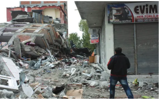
Turkey is located three main earthquake zone. These are as follows: The North Anatolian Earthquake Zone, Western Anatolia Seismic Zone, Southeastern Anatolia Seismic Zone. In recent years, occurence of earthquakes in Turkey especially Van and Erci have caused financial and moral damages so these shows that once again the reality of the earthquake. After these earthquakes, 604 people were died and over 2000 people were wounded. Around 100 buildings were completed collapse and number of the building known to be heavily damaged. After the earthquakes such as this and others have caused damaged in structures.
Fig 1. 23 Octaber 2011 Earthquake in Van
Not only the earthquakes causes damage in the structures but also blasting, explosions and e.t.c can cause damaged in structures.
Non-structural damages: These damages are not effect the integrity of structures
such as windows, doors, partitions e.t.c
Structural damages: These damages are effect the integrity of structures or
buildings such as beam, column, slabs, foundation, shear wall, beam-column joint. Structural damages can be minor, moderate and severe damage.
Due to the formation of earthquakes or damages, strengthening of existing structures has been an important issue.
Also reinforced concrete structures may need strengthening reasons such as;
• incorrect calculations and applications of project
• the use of unsuitable materials for standarts or guidelines
• the uses of low –strength material (the low quality of concrete )
• inadequate lateral reinforcement
• changing the intended uses of buildings thus usage load !ncreased
• additional storey
• corrosion (environmental factors)
• poor workmansh!p
• changing the guidelines or the formation of new standarts e.t.c..
Shortly, strengthening is not only for structures damaged by the earthquake also a possible earthquake or exist for inadequate strength of the current situation of the reinforced concrete structures and components.
In aditi!on to traditional strengthening methods such as externally-bonded steel plates, jacketing etc, advanced composite materials has became widespread in the strengthening of reinforced concrete (RC) structures. Espeacially uses of fibre reinforced polymers (FRP) materials for strengthening has rapidly increased in recent
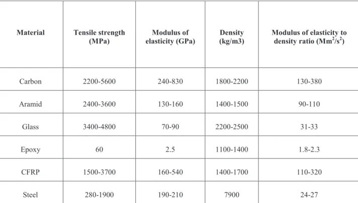
years. Due to their lightweight, high strength, resistance to corrosion, speed and ease of aplication and formed on site into different shapes can be made them preferences. The composite materials (FRP) aplications are used for strengthening of reinforced concrete structures instead of classical methot. Due to the benefits of this materials externally bonded FRP sheets and strips are currently the most commonly used techniques for strengthening in concrete structures.Table 1 show that typical strength and stiffness value for different materials in strengthening.
Table 1. Typical strength and stiffness values for materials used in retrofitting (Piggott, M. 2002)
Material Tensile strength (MPa) Modulus of elasticity (GPa) Density (kg/m3) Modulus of elasticity to density ratio (Mm2/s2) Carbon 2200-5600 240-830 1800-2200 130-380 Aramid 2400-3600 130-160 1400-1500 90-110 Glass 3400-4800 70-90 2200-2500 31-33 Epoxy 60 2.5 1100-1400 1.8-2.3 CFRP 1500-3700 160-540 1400-1700 110-320 Steel 280-1900 190-210 7900 24-27
1.1. Previous Research
Lam and Teng (2003) (I), proposed a simple design-oriented stress-strain model for FRP-confined concrete in rectangular columns. This model is an extension of a recent design-oriented stress-strain model developed for concrete uniformly-confined with FRP based on test results of circular concrete specimens. Lam and Teng 2003 (II), proposed a new design-oriented stress–strain model for concrete confined by FRP wraps with fibres only or predominantly in the hoop direction based on a careful interpretation of existing test data and observations. But this model reduces directly to idealized stress–strain curves in existing design codes for unconfined concrete. In the development of this model, a number of important issues including the actual hoop strains in FRP jackets at rupture, the sufficiency of FRP confinement for a significant strength enhancement, and the effect of jacket stiffness on the ultimate axial strain, were all carefully examined and appropriately resolved.
Campione et. al. (2004), investigated the compressive behavior up to failure of short concrete members reinforced with fiber reinforced plastic (FRP). Rectangular cross-sections are analysed by means of a simplified elastic model.The effect of local reinforcements constitute by single strips applied at corners before the continuous wrapping and the effect of round corners are considered. Analytical results are compared to experimental values available in the literature presents a theoretical model for prediction the maximum strength and strain capacities of short compressed column externally wrapped with FRP sheets. Members with rectangular crosssections and sharp or round corners were analysed.
Shehata et al. (2002), investigated the gain in strength and ductility of concrete columns externally confined by CFRP wrapping that included tests on 54 short column specimens. The column cross section shape (circular, square and rectangular) and the amount of confinement expressed in the number of CFRP sheet layers applied to the models (one or two layers) were variables in the study. On the basis of the obtained results, equations were proposed to calculate the confined concrete strength and the ultimate confined concrete strain as a function of the confining lateral stress for each of the cross section geometry used, circular, square and rectangular.
Mirmiran et al. (1998), studied effect of shape, length and interface bond on FRP-confined concrete. Over 100 specimens subjected to uniaxial compression. Sguare sections are less effective in confining concrete than circular sections and effectiveness is measured by a modified confinement ratio that is function of the corner radius and the jacket’s hoop strength. Length effect in short columns of up to 5:1 and %10 eccentricity and %20strength reduction in pure compression.But adhesive bond doesn’t change load –carrying capacity of FRP-confined conrete, mechanical bond considerably enhance the load –carrying capacity of the column by providing an effective load distribution mechanism.
Saadatmanesh et al. (1994), presented a new technique for seismic strengthening of concrete columns. The technique requires wrapping thin, flexible high-strength fiber composite straps around the column to improve the confinement and, so, its ductility and strength. Analytical models are presented that concrete columns strengthened with composite straps can be used to increase effectively the strength and ductility of seismically deficient concrete columns. The result of the study: failure strain of the concrete increased, in comparison to the unconfined concrete. If the volumes of straps are equal, increase of ultimate axial load and ductility for strengthening with carbon fiber is larger than strengthening with E-glass. The technique they used increased the axial carrying capacity of the column and the ductility factor increases linearly with increase in strap thickness.
Saadatmanesh et al. (1997), investigated the flexural behavior of earthquake-damaged reinforced concrete columns repaired with prefabricated fiber reinforced plastic (FRP) wraps. Four column specimens were tested to failure under reversed inelastic cyclic loading to a level that can be considered higher than would ocur in a severe earthquake. The columns were repaired with prefabricated FRP wraps and retested under simulated earthquake loading. FRP composite wraps were used to repair damaged concrete columns in the critically stressed areas near the column footing joint. The results indicate that the proposed repair technique is highly effective. Both flexural strength and displacement ductility of repaired columns were higher than those of the original columns.
Rausakis et al. (2007), performed finite element analyses to investigate the behavior of square reinforced concrete (RC) columns strengthened by fiber reinforced polymer (FRP) sheet confinement. The study focuses on the contribution of FRP confinement in prevention of longitudinal bars buckling in cases of inadequate stirrup spacing. The analysis is presented that includes low concrete strength columns with different qualities of steel reinforcement (yield stress of the longitudinal bars). The results indicate that adequate FRP confinement can provide the restrictive mechanism to resist buckling of longitudinal steel reinforcement, while the lower the yield stress of bars, the lower the gain in strength of FRP confined columns and the lower the strain ductility achieved.
Oncu et all.(2010), investigated to determine behaviour of RC sections strengthening by wrapping with CFRP subjected to cylic loading. The results of damaged concrete specimens that wrapping with CFRP shows positively effects to resistance against cyclic loads.
2. REINFORCED CONCRETE STRUCTURAL ELEMENTS
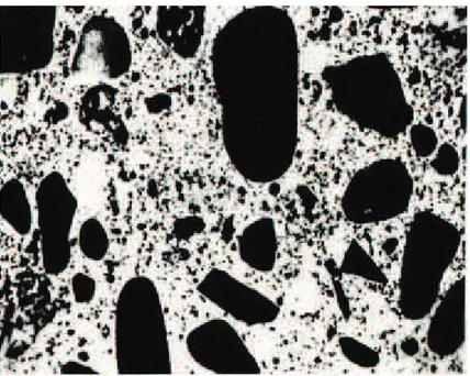
Concrete is a well-known composite material that has been composed of cement paste and aggregates. The paste, composed of portland cement and water, coats the surface of the fine (sand) and coarse (gravel) aggregates. Due to a chemical reaction called hydration, the cement paste hardens and gains strength to form the rock-like mass known as concrete.
Fig.2.1: Typical Concrete Sample.
Fig 2.1 show that the typical concrete sample, which is composite materials, is occured sand and gravel are combined with the matrix (cement).
8
Fig 2.2 :Typical Concrete Components
Figure 2.3. Percentage of Concrete Components
CONCRETE CEMENT PASTE cement+water AGGREGATE Coarse aggregate (gravel ,crushed stone
etc)
Fine aggregate (sand, rock ,dust,etc)
ADD T VES! (CHEM CAL!AND! M NERAL) % 0.5-8 Air % 7-15 Portlant Cement % 24-28 Coarse Aggregate %30 -50 Fine Aggregate % 14-18 Water
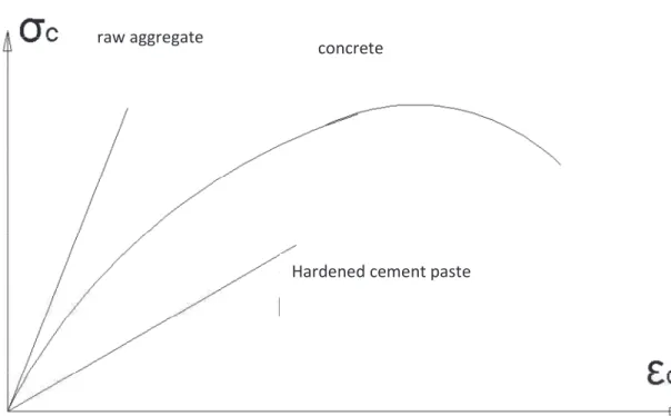
Figure 2.4. Concrete and It’s Components of Stress-Strain Diagram
It is used for a long time in the construction of buildings and bridges. Good strength under compression ,easy to be given shape, durability, good fire resistance, high water resistance, low maintenance, and long service life are the superior side of the concrete.On the other hand weak sides are poor tensile strength , brittleness ,volume instability and formwork requirement. The most common type of concrete reinforcement is a steel bar.When the rods are placed in the concrete is called reinforced concrete.
The pioneers of reinforced concrete in building construction were two Frenchmen J. Louis Lamport and Francois Coignet. In 1850, Lamport built a small boat of reinforced concrete. A few years later F. Coignet published a document on the principles of reinforced concrete construction.
The two German engineers, Wayss and Bauschinger who investigated Monier system in 1887, was puplished a report then the use of reinforced concrete construction spread quickly (Ersoy et al. 2003).
2.1. Models of Concrete
Many models for the stress-strain relation of concrete have been proposed up to the present. But on this section used of common mathematical models for concrete will be discussed. Stress strain relation is not unique it depends on the variables or changable with variables. Commanly used models for concrete are; Hognestad (1951), Kent and Park (1971), Sheikh and Üzümeri (1982), Mander Concrete Models which will be discussed in this study.
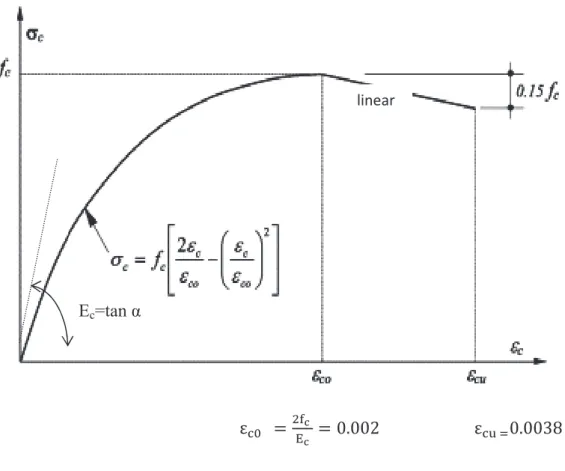
2.1.1. Concrete Model Proposed by Hognestad (1951)
The model proposed by hognestad are widely used stress-strain curve for the behaviour of normal strength and provided to be a satisfactory model for unconfined concrete, shown in Fig. In the model, - curve up to the peak portion asumed a second-order parabola and part of the decline is assumed to be a linear. The maximum stress, usually taken as 85% cylindrical strength of concrete. (fc= 0.85 fck).
Max compressive stress corresponding to strain ;
c0 can be taken 0.002.
(
c0 =0.002)
The model for the following equation Ec, modulus of elasticity, is proposed by the Hognestad.
Ec = tan = 126800 + 460 fc(kgf/cm2)
The part up to the peak of the curve(second degree parabola);
Strain (
c0 ) corresponding to max compressive stres ( fc); is described
Value of the ultimate compressive strain , cu is usually taken as 0.0038;
cu = 0.0038 (Ersoy et all,2003)
Fig 2.5. Hognestad Model (1951)
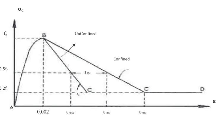
2.1.2. Concrete Model Proposed by Kent and Park Model (1971)
Kent and Park (1971) proposed a stress-strain equation for both unconfined and confined concrete. In their model they generalized Hognestad’s (1951) equation to more completely describe the post-peak stress-strain behavior. In this model the ascending branch is represented by modifying the Hognestad second degree parabola by replacing fc=fck and
co = 0.002
The part up to the peak of the curve (second degree parabola) ;
The post-peak branch was assumed to be a straight line whose slope was defined primarily as a function of concrete strength;
!" #$
% )*&' +)(%
"% , &* -. /0.
1 2 3' %
2 4+
Where; =Concrete stress; b" = big size of the core concrete (area inside the stirrup), s = stirrup spacing, s = stirrup percent density,
5 678!9 ' : # ; 5< 9 =!: #
Fig 2.6. Stress-Strain model for confined and unconfined concrete – Kent and Park (1971) model
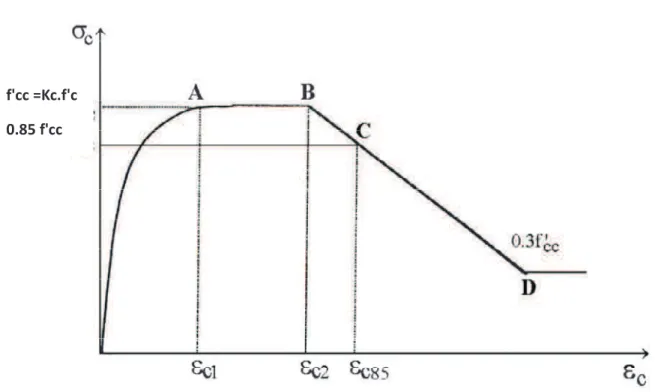
2.1.3. Concrete Model Proposed by Sheikh and Uzumeri (1982)
Sheikh and Uzumeri (1982) proposed a stress-strain equation for confined concrete in tied columns. An analytical model (Sheikh and Uzumeri 1982), which considers distribution of the longitudinal reinforcement and the configuration of the rectangular column ties on the effectiveness of the confinement.The proposed confinement efficiency of confined concrete can be described by Equations and model shown in Fig 2.7.
f 'cc = compressive strength of confined concrete; f c' = cylinder strength of unconfined
concrete; Kc = confinement coefficient ,
f'cc =Kc.f 'c (1)
fc
0.002 50u 50c 20c
> ?)* @8: ; % %:AB;; 5: C 5D 5D (2)
EF G <H I.= (3)
where As: Cross sectional area of longitudinal reinforcement, C= distance between laterally supported longitudinal bars, s = tie spacing, sh = ratio of the volume of tie steel to the volume of core, bc =dimension of concrete core, fsh =stres in the lateral steel
c1 = 80 .Kc. fc'.10-6 (4)
" " ? J*( K G 0. L MNOCPPNO (5) " (% G -.,/0. ? " (6)
In equation 1 and 2 diamensions, the stresses and Pocc are should be taken mm, MPa
and kN.
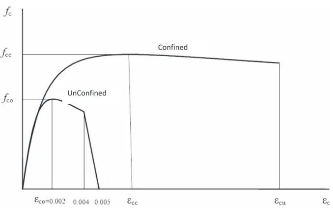
2.1.4. Concrete Model Proposed by Mander Et Al (1988)
Mander et al. (1988) have proposed a unified stress-strain model for concrete subjected to both static and dynamic loading, either monotonic or cyclic and confined by transverse reinforcement. The concrete section may contain any general type of confining steel: either spiral or circular hoops; or rectangular hoops with or without supplementary cross ties.
The compressive strength of confined concrete is proposed to be obtained as:
Q R R+) ' QS K GT ? GT/ ?U V*PW P PW P L " " F ? G KP P L X Y Y +YNZ [ G C
where f'cc anc f'1 is defined later
Fig 2.8. Mander Concrete Model (1988)
f 'cc is the maximum compressive strength of confined concrete, c is the compressive
strain of concrete, f'co is the maximum compressive strength of unconfined concrete, cc
is the compressive strain of confined concrete corresponding to the maximum
compressive strength of confined concrete, and co is the strain corresponding to the
maximum compressive strength of concrete, x: effecctive strain ratio
“x = c / cc” c = longitudinal compressive concrete strain. r: modulus of elasticity ratio
2.2. Repair and Strengthening of Reinforced Concrete Structures 2.2.1. Repair
Basic purpose of repair is to bring back to function of the deteriorated, damaged components, or elements of a structure or the architectural shape of the building. So that all elements and structure is gone back to initial state and the functioning of building is
restructuring quickly. Such as; repairing doors, windows, water and gas pipes, electric wiring, roofing tiles, cracks e.t.c. Reconstruction of boundary walls, non-structural walls, smoke chimneys,
2.2.2. Strengthening
Strengthening is the process of enhancing capacity of damaged components of structural concrete to its original design capacity, or an improving over the original strength of structural concrete. Reinforced concrete structures require strengthening due to:
• earthquakes
• accidents; such as collisions, fire, explosions
• corrosion of the reinforcement
• changes of the design parameters or new design standards,
• incorrect calculations and applications of project
• the use of unsuitable materials for standarts or guidelines
• the uses of low –strength material (the low quality of concrete )
• inadequate lateral reinforcement
• changing the intended uses of buildings thus usage load !ncreased (excessive
loading )
• additional storey
! 2.2.2.1. Strengthening Method
Common strengthening methods are known as;
• Concrete Jackets
• Steel jacketting
• Externally bonded steel plates
• External Post-Tensioning
The most important step in retrofitting is the selection of an suitable interference technique based on the structural type and its vacancy.On the other hand, type and location of problem, availability of time and skill, appearance and cost is an important factor that selection of strengthening method.
According to JSCE, 1999; Retrofitting of structures shall flowed as follows:
• ‘ Identify the performance requirements for the existing structure to be retrofitted and draft an overall plan from inspection through selection of retrofitting method, design of retrofitting structure and implementation of retrofitting work.
• Inspect the existing structure to be retrofitted.
• Based on the results of the inspection, evaluate the performance of the structure and verify that it fulfills performance requirements.
• If the structure does not fulfill performance requirements, and if continued use of the structure through retrofitting is desired, proceed with design of the retrofitting structure.
• Select an appropriate retrofitting method and establish the materials to be used, structural specifications and construction method.
• Evaluate the performance of the structure after retrofitting and verify that it will fulfill performance requirements.
• If it is determined that the retrofitting structure will be capable of fulfilling performance requirements with the selected retrofitting and construction methods, implement the retrofitting work. ’
The methods of strengthening:
Concrete Jacketing: Concrete jacketing is typically applied methods of repair and
strengthening of concrete members. Jacketing is one of the most generally used techniques to strengthen reinforced concrete (RC) columns. The size of the jacket, the number and diameter of the steel bars used in the jacketing process depend on the structural analysis that was made to the column. If !t is required, beams, slabs, and walls can be enlarged to add stiffness or load-carrying capacity. Extensive longitudinal and transverse reinforcement is added in the new layer of concrete (Fig 2.3), enhancing the shear and flexural strength and ductility. It is necessarry to provide a good bond between new and old concrete in reinforced concrete jacketing. Reinforced concrete jacketing can be applied one, two, three or four side of the column, depending on the state of the implementation and space around the column.
In order to made jacketting to required level jacketting should be,
• Strength of the new material must be greater than existing one
• Min 4 cm thicckness of the jacket for shotcrete application and min 10 cm thicckness of the jacket for cast- in –situ concrete
• New reinforcement and concrete is collaborated with existing concrete and reinforcement
This method aplication is difficult to construct in some active buildings such as hospitals, schools, industry e.t.c because of the implementation is taken time ,made noise and limited to use. Size of the column or reinforced concrete members is increased by concrete jacketing this make !ts usage very limited.
Reinforced concrete jackets are build by enlarging the existing cross section with a new layer of concrete and reinforcement. (Ersoy et al. 1993) Fig 2.3 show that the enlargement of cocrete and reinforcement.
Fig.2.9. Increasing the cross-sectional area of column by RC jacketing Concrete Enlargement Existing column Added longitudinal (Reinforcement (steel strips)
Fig.2.10. Typical concrete jacketting of reinforce concrete columns
Steel Jacketing & Externally Bonded Steel: Strengthening metod with steel plate
bond or steel welding in reinforced concrete is concerned are fast and effective. The steel jacket retrofit has been used as a method to enhance the shear strength and ductility of reinforced concrete (RC) columns in buildings. Confining reinforced concrete column in steel jackets is one of the remarkable methods to improve the axial load carrying capacity.
As compared with conventional hoops or spirals, steel jacket has an effective utility;
• to easily provide a large amount of transverse steel, hence strong confinement to the compressed concrete,
• to prevent spalling off of the shell concrete
The jacketting of the column with thin steel plates placed at a small distance from the column surface, with the occuring space being filled with non-shrinking grouts shown in Fig 2.11. A steel jacket usually consists of two half shells of steel placed around the column, and welded together after placing. The space between the
jacket and column is filled with pure cement grout. A space between the jacket joining member, to avoid the proba
could cause local buckling in the jacket.
effect. The jacket can be considered as similar to continuous hoop
‘The simplicity and speed of the jacketting critical intervention time immediately after a stro buildings such as hospitals and schools’.
Fig 2.11. Strengthening of RC column with Steel jacketting
The steel jacketing come out of angle profiles straps at the corner of the column shown in Fig 2.12
50x50x5 mm, diameter of round bars selected at least ø14 mm and steel st should be selected min 25 x4 mm and welded to the e
with pure cement grout. A space between the jacket joining member, to avoid the probability of direct load carrying action of the jacket, could cause local buckling in the jacket. The jacket provides a passive confinement
be considered as similar to continuous hoop-reinforcement.
ty and speed of the jacketting application provide a solution for critical intervention time immediately after a strong earthquake, particularly for special
s and schools’. ( Giorgio , 2003)
Strengthening of RC column with Steel jacketting
come out of angle profiles connected together with steel r of the column shown in Fig 2.12. Angle profile should be at least of round bars selected at least ø14 mm and steel straps size should be selected min 25 x4 mm and welded to the each other. Spaces between the
Spac Steel plate
Existing column
with pure cement grout. A space between the jacket and the action of the jacket, it The jacket provides a passive confinement
reinforcement.
application provide a solution for ng earthquake, particularly for special
connected together with steel Angle profile should be at least of round bars selected at least ø14 mm and steel straps size Spaces between the
angle profiles and the existing column surface’s should be filled with resin grout. A caging with concrete with welded fabrics is effective for corrosion or fire protection.
I-I
II-II
Fig 2.12. Steel profile jacketting
Steel strap
Fig:2.13. Typical steel jacketting of reinforce concrete columns
External Post-Tensioning Method: Post-tensioning is a method of strengthening
concrete or structural member with high-strength (prestressing) steel,strands, cables or bars, typically referred to as tendons. Post-tensioning tendons, are regarded “active” strengthening since it is prestressed. The steel is influential as reinforcement even though the concrete may not be cracked. It can be applied to reinforced and prestressed concrete members. Post-tensioning is a technique used to prestress reinforced concrete after concrete is placed. The tensioning provides the structural member with an immediate and active load-carrying capacity Post-tensioned structure can be designed to have minimum deflection and cracking, even under whole load. Post-tensioning applications in building unbonded tendons are typically prefabricated at a factory and transported to the construction site, ready to install. After the concrete is placed and has reached its required strength. Post tensioning methods for strengthening generally used to beam for enhanced the flexural capacity, improve the cracking performance and also have a beneficial effect on shear capacity when the application of an axial load
combined with a hogging bending moment. Strengthening of a beam with external tendons; shown in Fig 2.14. An equal number of tendons are typically used on each side of the beam. Tendon force and eccentricity are adjusted until an optimum solution for the required uplift force is obtained. Tendon geometry is easily modified with brackets and they can be placed at multiple locations along the beam. Fig. 2.15 – a shows an example of a beam bracket and how multiple beam brackets can be used to establish tendon geometry shown in 2.15- b. (Krauser, 2006)
26
Fig.2.15. Beam Brackets (Krauser, 2006)
Reinforcement located outside members so steel bars, cables or strands are anchored directly to the structures in external post-tensioning strengthening. On the other hand external cables can be placed inside plastic ducts and then filled with cementitious grout.
Anchorages are passed through a beam or column and anchored on the vertical surface; or attached to a bracket that envelops a column locations of induced forces when strengthening tendons pass through a beam, shown in Fig 2.16 a) ,b) ; Fig 2.16 c) show that column brackets ,which should be designed to have sufficient bearing to distribute the loads from the tendon to the concrete. (Krauser,2006)
a) Sample Beam Bracket
a- Cut Through Beam Indicating Critical Location of Shear Force
Fig 2.16. a) and b) the critical locations of induced forces beam; c) Anchorage bracket at column (Krauser,2006)
Cut Through Beam Indicating Critical Location
b- Plan View Indicating Induced Bending in the beam
c) Anchorage bracket at column
a) and b) the critical locations of induced forces when strengthening tendons pass through a beam; c) Anchorage bracket at column (Krauser,2006)
Induced Bending in the
c) Anchorage bracket at column
Reduced of deflection, impact resistance, high fatigue and other reason as explained above are the positive side of the using an externally-post tensioned method for strengthenings. On the other hand handling of tensioning device, exposed of circumferential influences, high cost and restricted of field area are the disadvantages of externally-post tensioned method for strengthenings.
Fig.2.17. Typical Strengthening of External Post Tensioned Photo
2.2.2.2. Strengthening Materials
Common strengthening materials are known as;
• Epoxy resin
• Shotcrete
• Epoxy Mortar
Epoxy Resin: Epoxt resins are used for small injection, surface coating or filling larger
cracks or holes. If !t is suitably applied, these materials could be bonded easily to concrete and are able to restoring the original structural strength to cracked concrete. The epoxy mixture strength is depend on the temperature of curing, lower strength for higher temperature and method of application. Viscosity must be suitable to the thickness of the crack to be injected. Cracks to be injected with epoxy resins should be between ~ 0.1 mm and ~ 6 mm in width. It is very difficult to retain injected epoxy resin in cracks greater than ~ 0.6 mm in width, although high viscosity epoxies have been used with some success. Epoxy resins cure to form relatively brittle materials with bond strengths exceeding the shear or tensile strength of the concrete. ( Guide to Concrete Repair,1996 )
Shotcrete: Shotcrete is a method where small layer of concrete or mortar is projected
under pressure using a feeder or "gun" onto a prepared surface to form structural shapes. It can be used for the strengthening or the repairing of reinforce concrete structures. Shotcrete is used in most cases as a strengthening or repairing or construction material because of !ts high strength, durability, low permeability, remarkable bond and aplicability of irregular shapes. Shotcrete has a two applied process these are:
Wet Mix Process: Cement, sand, and coarse aggregate are first conventionally mixed
with water, and introduced into the delivery equipment. Wet material is pumped to the nozzle where compressed air is added to provide high velocity for placement and compressed the wet mixture on to the desired surface.
Dry Mix Process : Dry cement, sand, and coarse aggregates (pre-blended dry materials) are mixed and placed into the delivery equipment. Compressed air transmits materials through a hose at high velocity to the nozzle, where sufficient water is added. Material is consolidated on the desired surface by the high-impact velocity.
Epoxy Mortar : Epoxy mortar is composed of epoxy resin and sand that is placed over
an epoxy bonding coat on hardened existing concrete. Epoxt mortar reach strength in few hours. It may be used when conducting minor repairs where the damage extends less than 40 mm into the concrete surface.
Fig.2.21. Epoxy Mortar
Frp Materials: This materials are considered as a composite materials and used in
strengthening in reinforced concrete structures and also civil engineering structures, which will be studied in this thesis and explained in detail below.
3. COMPOSITE MATERIALS
Composite material is a materials system combined of two or more micro- or macro-component that differ in form and chemical combination and which are fundamentally insoluble in each other. Use of composite materials are very important in the Automotive industry, construction industry, manufacturing industry and new technology products.
The purpose of the creating composite materials is obtained the new features which the components doesnt have alone. In other words, producted superior properties of a new material the production than existing components.
In modern materials engineering, composite usually refers to a "matrix" material that is reinforced with fibers (Roylance ,2000).
3.1. Clasification of Composite Materials
Composite Materials genarally classified as a ;
• Metal Matrix Composites (MMC)mmmmmmmmmmmmmmmmmm
• Ceramic Matrix Composites (CMC)
• Polymer Matrix Composites (PMC)
3.2. Types of Composite Materials
• Fibre- reinforced Composites • Particulate Composites • Laminar Composites
Table 3.1.Advantages and Disadvantages of Composite Materials
Advantages of Composite Materials Disadvantages of Composite Materials
• High strength to weight ratio • High stiffness to weight ratio.
• Air condition,corosion and chemicals resistance
• Lightweight, • High workability, • Easy formability
• Low transport cost due to lightweight • High fatigue and impact strength • Low heat conductivity
• Electrical insulation and conductivity
• High manufacturing costs • Brittle, not ductile failure
• Materials require refrigerated transport and storage and have limited shelf lives • Composites must be completely cleaned
of all contamination before repair. • Composites must be dried before repair
because all resin matrices and some fibers absorbmoisture.
• Repair at the original cure temperature requires tooling and pressure.
Fig 3.1. Stress Strain Diagram for Composite and It’s Phases
3.3. Fibers
Fibers are the effective reinforcements material, as they satisfy the required conditions and transfer strength to the matrix constituent influencing and enhancing their properties as required. The performance of a fiber composite is evaluated by its length, shape, orientation, composition of the fibers and the mechanical properties of the matrix. (Pandey ,2004)
The main fibre types used in civil engineerig are Carbon fibers (CFRP), Glass (GFRP) and Aramid (AFRP)
3.3.1. Types of fibers
3.3.1.1. Carbon Fibers (CFRP)
Carbon fibers are anisotropic in nature strength, excellent creep level,
density and high elastic modulus
expensive and anisotrophic materials and the weak sides of carbon fibers.
Fig 3.2. Typical Carbon fibers (CFRP)
3.3.1.2. Glass Fibers (GFRP
Glass fibers are isotropic in types of glass fibers are E-Glass, S glass fibers are: high strength, chemicals.
Fig 3.3.
bers (CFRP)
are anisotropic in nature Carbon fibre is produced at 1300ºC resistance to chemical effects, low conductivity nsity and high elastic modulus are the advantages of carbon fibers. Carbon fibers are
and anisotrophic materials and !t has a low compression strength
Typical Carbon fibers (CFRP)
(GFRP):
are isotropic in nature and most widely used filament. Common Glass, S-Glass and C -Glass.The characteristic properties of high strength, low cost, good water resistance and resistance to
3.3. Typical Glass fibers (GFRP)
produced at 1300ºC. High low conductivity, low arbon fibers are low compression strength these are
most widely used filament. Common The characteristic properties of resistance to
3.3.1.3. Aramid Fibers
Aramid fibers widespread known a structure of aramid fib
colours. Aramid fibers
tension applications (Cables and tendons) Aramids have high tensile strength, and densiy. Impact
five classes Kevlar
49, Kevlar-100,
Fig 3.5. Uniaxial tension stress
carbon FRP, AFRP = aramid FRP, GFRP = glass FRP. 3.1.3. Aramid Fibers (AFRP):
Aramid fibers widespread known as a kevlar fiber in the markets structure of aramid fibre is anisotropic in nature and usually
Aramid fibers moore expensive than glass, moderate stiffness,
tension applications (Cables and tendons) but lower strength in comprension. ids have high tensile strength, high stiffness.high modulus and low weigh
Impact-resistant structures can be produced from aramids
Kevlar with the different engineering properties
100, Kevlar-119, Kevlar-129
Fig 3.4. Typical Aramid fibers (AFRP)
tension stress-strain diagrams for different unidirectional FRPs a FRP, AFRP = aramid FRP, GFRP = glass FRP. (FIP Bulletin 14, 2001)
s a kevlar fiber in the markets. The usually are yellow in oderate stiffness, good in lower strength in comprension. high modulus and low weigh resistant structures can be produced from aramids. There are engineering properties. 29,
Kevlar-strain diagrams for different unidirectional FRPs and steel. CFRP = (FIP Bulletin 14, 2001)
Table 3.2 Mechanical properties of Fiber Types (Unal,O)
Material Specific gravity
(gr/cm3) Tensile Strength (N / mm2) Modulus of elasticity (N / mm2) Glass Fiber 2.54 2410 70000 Carbon Fiber 1.75 3100 220000 Kevlar Fiber 1.46 3600 124000 3.3.2. Oriantation of Fibers
The mechanical properties of FRP vary with the type and oriantation of the reinforcing fibers.(Malek et all,1998). Fibres can be orianted form of:
3.3.2.1. Continuous Form:
Continuous and aligned fibers are generally long and straight also fibers distributed parallel to each other.
3.3.2.2. Woven Form:
Fibers come in cloth form and provide multidirectional strength
3.3.2.3. Chopped Form (discontinuous):
Fibers are short and generally randomly and discountinuous arranged (fiberglass) which are shown in Fig.3.6..
Fig 3.6. Fiber oriantation in
Table 3.3. Fibre direction, arrangement and typical uses (Irw
Composite Type Carbon Fibre Sheet (CFS) Aramid Fibre Sheet (AFS) Glass Fibre Sheet (GFS) Carbon Fibre Laminate (CFL)
Fiber oriantation in a) continuous b)woven and c) chopped form
Fibre direction, arrangement and typical uses (Irwin and Rahman 2002)
Fibre direction Fibre arrangement Typical Application
Unidirectional Straight Increase in flexural and Shear capacity;confinement
Unidirectional Straight Special applications
Bidirectional Woven Increase in confinement and ductility Unidirectional Straight (partially pretensioned) Increase in flexural capacity
b)woven and c) chopped form.
Fibre direction, arrangement and typical uses (Irwin and Rahman 2002)
Typical Application flexural and apacity;confinement applications confinement flexural
3.4. Matrix Material
Matrix is the second major
the suitable matrix affects the efficiency of the required success in f purpose of the matrix is holds the fibres
protects the fibers from external !nfluences (
Fig 3.7
The material properties of moistur consideration for the choice of matrix. strength, strain, failure, fatigue, impact is also modulus and strength, the shear properties and the mechanical properties of the composites
Physical and chemical characteristics of the matrix temperature, viscosity and reactivity with fibres i
process. (FIP Bulletin 14, 2001) ! "
he second major component of the composite material. Selection of affects the efficiency of the required success in fibers.
olds the fibres together, transfers loads to the fibres and external !nfluences (corrosion, oxidation, abrasion).
3.7.Clasification of Matrix Material
The material properties of moisture and dewatering should also be
consideration for the choice of matrix. Shear stiffness, longitudinal compressive strength, strain, failure, fatigue, impact is also very important features. The t
the shear properties and the properties in compression
al properties of the composites which are a strong influence on the matrix Physical and chemical characteristics of the matrix such as melting or curing temperature, viscosity and reactivity with fibres influence the choice of the fabrication
! " #$ ! " ! " #$ Selection of The main to the fibres and
e and dewatering should also be taken into Shear stiffness, longitudinal compressive he transverse properties in compression are the which are a strong influence on the matrix.
melting or curing fabrication
% "
! "
3.4.1. Properties of a Matrix
• Reduced moisture absorption.
• Low shrinkage and low coefficient of thermal expansion
• Good flow characteristics
• Reasonable strength, modulus and elongation
• Must be elastic to transfer load to fibres.
• Strength at elevated temperature.
• Low temperature capability.
• Excellent chemical resistance.
• Should be easily processable into the final composite shape.
• Dimensional stability, (Pandey ,2004)
3.5. Adhesives
The purpose of the adhesive is to attach the composites to concrete surface, so that to provide a shear load path. The most common type of structural adhesives are Epoxy and Polyester, which are the polymer matrix materials (Polymeric matrix) shown in Fig 3.7 . Properties of Epoxy and Polyester adhesives are shown in Table 3.4
Table 3.4. Properties of Epoxy and Polyester Adhesives
Properties of Epoxy Adhesives Properties of Polyester Adhesives
• High cost
• Good electrical properties
• High bond strength and flexibility
• High temperature resistance,
• Low shrinkage during curing
• Better adhesion between fibre and matrix
• Resistance to chemicals , solvents and water • Resistance to creep and fatigue
• Limited temperature application range upto 175°C
• Moisture absorption affecting dimensional properties
• High thermal coefficient of expansion
• Extremely harmful to the skin
• Low cost
• Good mechanical strength
• Good electrical properties
• Low viscosity and versatility
• Good heat resistance
• Cold and hot molding
• Curing temperature is 120°C • Good handling properties
• Poor chemical resistance
• High curing shrinkage
Table 3.5. Properties of Fiber Composites with Adhesives
Materal Specific gravity
(gr/cm3)
Tensile Strength
(N / mm2)
Modulus of Elasticity
(N / mm2)
Glass fiber – polyester 1,5 – 2,1 200 – 340 55000 – 130000
Carbon fiber – epoxy 1,5 – 1,8 1860 145000
Kevlar fiber – epoxy 2,36 2240 76000
Boron fiber - epoxy 1,4 1240 176000
3.6. Fiber Reinforced Polimer (FRP) Material
Fiber-reinforced polymer (FRP) is a composite material consisting of high tensile-strength fibers bonded to the concrete surface using an epoxy resin or embedded in a matrix of polymer resin. FRP materials have been used for many years in the automotive and aerospace sectors. FRP material are used as external reinforcement in the construction industry since 1970. (Is!s Canada,2004).
Today, these FRP products take the form of bars, cables, 2-D and 3-D grids, sheet materials, plates, etc. FRP products may succeed in the same or better reinforcement objective of commonly used metallic products such as steel reinforcing bars, prestressing tendons, and bonded plates. ( ACI 440,2002)
In the last decade, the use of fibre reinforced polymers (FRP) as reinforcement is rapidly growth for structural strengthening in civil engineerings applications.
The most commonly available fiber reinforced polymer (FRP) types are the carbon (CFRP), the glass (GFRP) and the aramid (AFRP) fibers which were explained above.
For the purposes of external reinforcement of concrete, there are essentially two classes of FRP materials are available mainly in the form of :
• Plates; rigid thin unidirectional strips made by pultrusion
• Sheets or Fabric ; unidirectional made of fiber at least two distinct directions
,pre-impregnated
3.6.1. Installation Techniques of Fiber Reinforced Polymers (FRP) Materials
There are three installation techniques of Fiber Reinforced Polymers (FRP) materials is used in construction sectors. These are wet or hand lay-up, Prefab Systems and Prepreg Systems.
3.6.1.1. Wet Lay-Up Systems (Hand Lay-up)
In this technique, composed by dry multidirectional or unidirectional fiber sheets or fabrics of raw or preimpregnated fibres are saturated with an epoxy adhesive resin and placed on the surface of the concrete. Sheets or fabrics are more flexible and can be used to plane as well as sharp corners should be rounded. Shaped and cured in-situ.
3.6.1.2.Prefab Systems
This systems are composed by pre-cured rigid FRP strips or plates (laminate) to the surface of the concrete using an epoxy adhesive which are generally best suited for flat and straight surfaces.
3.6.1.3. Prepreg (Special) Systems
This system composed by uni or multi directional of fibers sheets.It is generally special systems, e.g. automated wrapping, prestressing etc Special systems, e.g. automated wrapping, prestressing etc.
The achievement of FRP strengthening is highly dependent on the installation of the FRP.The following items shoul be considered during construction to help ensure a successful FRP aplications. These are :
1 Contractor Qualifications
2 Surface Preperation
3 Galvanic Corrosion
4 Pull Tests to CheckBond
5 Witness Panels/Laboratory Testing to Check Laminate Strength
6 Testing Laboratory Personnel Experience (Williams et al.2008)
Fig 3.8. Typical Prefab system (Laminates or strips) and wet lay-up system (sheets or fabrics) photos
! & '
(a) (c) (b) (d)
Fig 3.9. FRP techniques: (a ) Hand lay-up of CFRP sheets or fabrics. (b) Application of prefabricated strips. (c )Automated RC column wrapping. (d) Schematic. Photograph of robot-wrapper. (Fib Bulletin 14, 2001).
3.6.2. Physical and Mechanical Properties of FRP
Table 3.6. Advantages and Disadvantages of FRP Reinforcements
Advantages of FRP Reinforcement Disadvantages of FRP Reinforcements
High longitudinal strength (varies with sign and direction of loading relative to fibers)
No yielding before brittle rupture
Corrosion resistance (not dependent on a coating) Low transverse strength (varies with sign and direction of loading relative to fibers)
Nonmagnetic Low modulus of elasticity (varies with type of
reinforcing fiber)
High fatigue endurance (varies with type of reinforcing fiber)
Susceptibility of damage to polymeric resins and fibers under ultraviolet radiation exposure
Lightweight (about 1/5 to 1/4 the density of steel) Durability of glass fibers in a moist environment
Low thermal and electric conductivity (for glass and aramid fibers)
Durability of some glass and aramid fibers in an alkaline environment
- High coefficient of thermal expansion
perpendicular to the fibers, relative to concrete
- May be susceptible to fire depending on matrix
type and concrete cover thickness
3.6.3. FRP Strengthening
Uses of fibre reinforced polymers (FRP) materials for strengthening has rapidly increased in recent years. Due to their lightweight,high strength, resistance to corrosion, speed and ease of aplication and formed on site into different shapes can be made them preferenced material in many strengthening applications.
The main uses of externally bonded FRP (fibre-reinforced polymers) in strengthening of existing reinforced concrete elements for;
• Confinement
• Flexural Strengthening (Bending)
• Purpose of Blast Resistance
• Deflection Control
• Shear strengthening,
High Strength Polymer Fabrics are used in:
Strengthening of reinforced concrete beams against bending and shear,
Strengthening of reinforced concrete slabs against bending,
Enhancement of the shear capacity, ductility and compressive strength of columns,
Strengthening of wooden beams against bending,
Strengthening of masonry structures.
3.6.3.1. Strengthening of Reinforced Concrete Structural Members with FRP
Beams – Bending (Flexure) and Shear
Strengthening with externally bonded with Frp materials are used in beams for purpose of bending and shear. Carbon fiber polymer layer aplicated the lower face for the bending.
Fig.3.10. Application of FRP on reinforced concrete beams for seismic retrofitting
Columns- Shear capacity ,Ductility ,Compressive Strength and Confinement
Strengthening with externally bonded with Frp materials are used in column for confinement, enhancement of ductility and compressive strength besides shear.
Fig.3.11. Application of FRP on reinforced concrete column for seismic retrofitting
Slabs- Bending
Strengthening with Frp materials are used in slabs for enhancement flexural capacity.
(a) (b)
Fig 3.13. Typical FRP applications as strengthening materials strengthening of slab; (b) flexural strengthening of beam; column; (d) wrapping of concrete tank; (e) shear stre 2001).
Fig 3.14.Typical FRP Application Site a (e)
Typical FRP applications as strengthening materials of RC structures: (a) flexural slab; (b) flexural strengthening of beam; (c) shear strengthening and confinement of wrapping of concrete tank; (e) shear strengthening of beam-column joint. (Fib Bulletin 14,
Application Site as Strengthening Materials of RC Structural Elements and confinement of
Bulletin 14,
3.7. Models of Concrete Corresponding to Stress-Strain Confined by Fiber Composites
The confinement stregth of the concrete model form generaly shown in equation which is related to the confinement pressure;
where , ƒ1 = confinement pressure, k1 =coefficient of effeciveness,
3.7.1. Model Proposed by TDY2007
This model mentioned information attachment 7.E in TDY2007; ‘Effects of FRP
Confinements on Strength and Duct!lty of RC Columns’ Axial compression strength of
confined columns can be received as;
where fcc =f’cc= compressive strength of confined concrete, fcm = f’co= unconfined
concrete strength
As shown in model, strengthening limited where the compressive strength of confined concrete is not exceed 20% of the current strength( ) $ * ' applicated.
a defined as a shape factor
!"# $%% & %' ( $)
*+,- '"" .%' $%% & %' ( $)
& + & /+,, & ' (#)0!"# $%% & %' ( $)
1
23 4 5679789
n = number of plies of FRP reinforcement, tf =nominal thickness of one ply of the FRP
reinforcement, b and h are width of rectangular cross section, and overall thickness of a member
f 0.004 and f 0.50 fu
f and fu are a strain level in the FRP reinforcement and design rupture strain of FRP reinforcement and also Ef is a tensile modulus of elasticity of FRP.
Enhancement of column ductility with FRP;
To increase the ductility of confining columns with FRP, ratio of the long dimension of column cross-section to short dimension of column-cross-section should not exceed 2.
(b / h 2)
cc = 0.002 (1+15 ( ƒ1 / fcm)0.75 )
where cc is a concrete strain corresponding to confined concrete compressive strength
(TDY2007)
3.7.2. Model Proposed by ACI 440
Bonding FRP systems can be used to increase the axial compression strength and also increase the axial tension strength of a concrete member. Confinement is also used to enhance the ductility of members subjected to combined axial and bending forces. To determine the full stress-strain behavior of FRP-confined concrete, the compressive strain in the concrete (longitudinal strain) must be related to the strain developed in the FRP jacket (transverse strain). The strain in the FRP jacket may then be used to determine the confining pressure and the resulting increase in the compressive stress in the concrete.