Experimental demonstration of subwavelength
focusing of electromagnetic waves by
labyrinth-based two-dimensional metamaterials
Irfan Bulu, Humeyra Caglayan, and Ekmel OzbayDepartment of Physics and the Nanotechnology Research Center, Bilkent University, Bilkent, 06800 Ankara, Turkey Received August 26, 2005; revised November 1, 2005; accepted November 1, 2005; posted November 8, 2005 (Doc. ID 64462)
We studied focusing in a two-dimensional metamaterial that was based on a labyrinth structure. We theo-retically showed that the labyrinth-based metamaterial exhibits negative indices of refraction between 6 and6.4 GHz. We experimentally studied the focusing effect by measuring electric field intensities on the output side of the metamaterial when the source was placed in front of the input side of the metamaterial. Our experimental results showed that it is in fact possible to focus the source field with half-widths as small as/4 by using the labyrinth-based metamaterial. © 2006 Optical Society of America
OCIS codes: 350.4010.
Left-handed materials have recently attracted much attention in the scientific community. This new type of artificial material can provide simultaneous nega-tive permittivity共⑀兲 and permeability 共兲 over a cer-tain frequency range.1 In particular one fascinating consequence of simultaneous negative permittivity and negative permeability is the possibility of focus-ing electromagnetic waves beyond the diffraction limit. Pendry2 predicted that a slab with ⑀= −1, = −1 may recover evanescent components of the field emitted from a source. In addition, because of nega-tive refraction, such a medium focuses the propagat-ing components of the source field. As a result, it may be possible to focus all of the Fourier components of the field emitted from a source. Pendry coined the term superlens for structures that have these proper-ties. However, until now Pendry’s prediction has been subject to some criticism.3
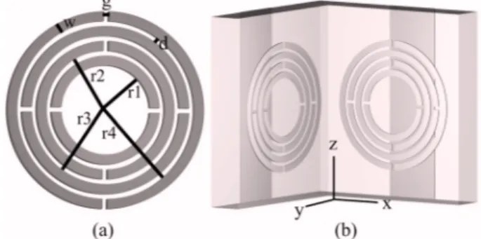
A common method for realizing simultaneous nega-tive ⑀ and is through the periodic arrangement of metallic wires and split-ring resonators. It was shown that the periodic arrangement of wires may provide negative⑀values below a certain frequency.4 On the other hand, negative over a certain fre-quency range is provided by a periodic arrangement of split-ring resonators.5However, it is now well un-derstood that split-ring resonators have two rather serious problems, one of which is bianisotropy,6and the other is electric coupling to the magnetic resonance.7These two issues make it difficult to ob-tain isotropic left-handed structures by using a peri-odic arrangement of wires and split-ring resonators. We recently addressed both of these issues by intro-ducing a modified split-ring resonator structure called the labyrinth structure.8The schematics of the labyrinth structure are shown in Fig. 1(a). A medium composed of a periodic arrangement of labyrinth structures does not exhibit bianisotropy. In addition, the magnetic resonance of the labyrinth structure cannot be excited via incident electric fields.
In the present work we investigated the possibility of subwavelength focusing of electromagnetic waves by using a metamaterial based on the labyrinth
structure. First, we theoretically showed that a me-dium composed of a periodic arrangement of wires and labyrinth structures exhibits negative indices of refraction. Then, we experimentally studied the fo-cusing effect. Our results showed that it is possible to focus electromagnetic waves emitted from a finite-size source with a half-power width of/4 by using a left-handed metamaterial based on the labyrinth structure.
The metamaterial medium that we used was com-posed of a two-dimensional periodic arrangement of wire stripes and labyrinth structures. The unit cell of the metamaterial structure is shown in Fig. 1(b). The wire stripes were printed on the back of standard FR4 substrates, and the labyrinths were printed on the front faces. The thickness of the metal, copper, was 0.05 mm. The width of the wire stripes was 2.5 mm. The lattice constant along the x and y direc-tions was 8.8 mm (0.18, where corresponds to 6.3 GHz). There were 68 layers along the x direction and 5 layers along the y direction. The width of the structure was 0.92. The height of the structure was 20 layers. This metamaterial medium has a left-handed transmission band between 5.9 and 6.5 GHz (Fig. 2 inset).
Several methods, such as procedures for retrieval from S parameters, can be used for the determina-tion of the index of refracdetermina-tion.9 Another rather
Fig. 1. (a) Labyrinth structure: r1 = 1.35 mm, r2 = 1.8 mm,
r3 = 2.25 mm, r4 = 2.7 mm, g = 0.15 mm, w = 0.3 mm, and d
= 0.15 mm. (b) Unit cell of the two-dimensional labyrinth-based left-handed metamaterial.
814 OPTICS LETTERS / Vol. 31, No. 6 / March 15, 2006
straightforward method makes use of the phase shifts when the size of the structure along the propa-gation direction is increased.10It was experimentally shown10that this method can accurately describe the real part of the index of refraction values for metamaterials even when the transmission is below −10 dB. Consider two pieces of homogeneous mate-rial with lengths of L1 and L2. The phase difference
introduced due to the difference in lengths of the pieces can be written as⌬= −k0n共L2− L1兲, where k0
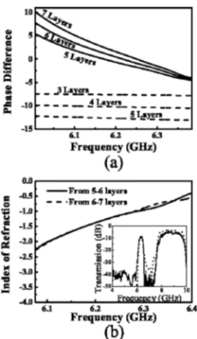
is the free-space wave vector. We used the −k0 con-vention in this study. To theoretically determine the phase shifts when the number of layers along the propagation direction is increased, we performed finite-integration method simulations by using a commercially available software program.11 The simulation results for the phase differences between the ends of five-, six-, and seven-layer-long metamaterials are shown in Fig. 2(a). For compari-son, we plotted the phase differences between the ends of three-, four-, and five-layer-long homoge-neous, isotropic FR4 slabs. First, note that the phase differences for the FR4 slabs advance in the negative direction when the number of layers is increased, as is expected from a medium with a positive index of refraction, whereas the phase differences between the ends of the metamaterial advance in the positive direction with increasing length along the propaga-tion direcpropaga-tion. In addipropaga-tion, the phase differences for different lengths of metamaterials do not change sig-nificantly around 6.4 GHz. We determined the index of refraction for the metamaterial medium by using the phase shifts shown in Fig. 2(a). The results be-tween 6.08 and 6.4 GHz are plotted in Fig. 2(b). The frequency range was chosen in order to have a
trans-mission that was above −20 dB for accurate phase determination. The index of refraction is negative within this frequency range. In addition, there is a frequency range around 6.28 GHz at which the index of refraction is close to −1.
Encouraged by our theoretical results, we studied the focusing properties of the labyrinth-based left-handed metamaterial. In our experiments we used monopole antennas as the source and receiver. We placed the source antenna in front of the surface of the labyrinth-based metamaterial. The axis of the source and receiver antennas were arranged parallel to the z axis. The length and diameter of the mono-poles were 3 cm and 1.5 mm, respectively. We mea-sured the electric field intensities over an area of 200⫻100 mm 共4.25⫻2.1兲 on the output side of the left-handed metamaterial in steps of 2.5 mm 共0.052兲, where corresponds to 6.3 GHz. The measured electric field intensities when the source antenna was placed 2 cm 共0.42兲 and 1 cm 共0.21兲 away from the input surface of the metamaterial are plotted in Figs. 3(a) and 3(b), respectively. The mea-surement frequency was 6.3 GHz. Note that the sur-face of the metamaterial was parallel to the x axes. Figures 3(a) and 3(b) clearly demonstrate the focus-ing of the source field on the output side by the left-handed metamaterial when the source was placed ei-ther 2 or 1 cm away from the input surface. The maximum field intensity along the y axes was ob-served at 10 mm 共0.21兲 when the source was 2 cm 共0.42兲 away from the input surface and at 17.5 mm 共0.37兲 when the source was 1 cm 共0.21兲 away. The half-widths of the intensity profiles along the y axis for both cases were 19 mm, ⬇/2.5. Moreover, the field intensities decay as 1 / r2along the y axes, where r is the distance from the focusing point. There are
some extra features appearing in the image. We at-tribute these extra features to the interference from the waves reflected by the laboratory environment. The intensity profiles along the x axis are shown in Fig. 4. In addition, we plotted the measured intensity
Fig. 2. (a) Phase differences between the ends of isotropic FR4 slabs (dashed curves) and the labyrinth-based metamaterial (solid curves). (b) Calculated indices of re-fraction for the labyrinth-based metamaterial. Inset, mea-sured spectrum of transmission through the labyrinth-based composite metamaterial medium (solid curve) and the simulated transmission spectrum (dotted curve).
Fig. 3. (Color online) Measured electric field intensities on the output side of the metamaterial when the source was (a) 2 and (b) 1 cm away from the input surface of the metamaterial.
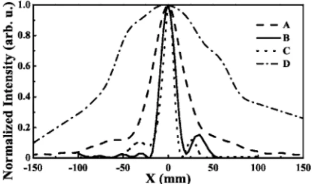
profile along the x axis when the source and receiver antennas were placed 2 cm apart from each other in free space (dashed curve in Fig. 4). The measured half-width of the intensity profile in free space, with-out the metamaterial between, was 40 mm, ⬇. Without the metamaterial, even at such a close dis-tance, the source field could not be resolved with a resolution below the wavelength. On the other hand, the half-width of the intensity profile on the output side of the metamaterial along the x axes was 12 mm, ⬇/4, when the source was 1 cm away from the input surface and was 16 mm,⬇/3, when the source was 2 cm away from the input surface. As a result it was possible to resolve the source field with a resolution below the wavelength when the metamaterial was in-serted between the source and the receiver antennas. The focusing property of the metamaterial was not restricted to 6.3 GHz. We observed the focusing effect for a range of frequencies between 6.2 and 6.37 GHz, although the focusing was not as sharp as for 6.3 GHz. Note that the source and image distances do not add up to the width of the slab 共0.92兲. We at-tribute this to the complex part of the index of refrac-tion.
In conclusion, we theoretically showed that a metamaterial based on the labyrinth structure exhib-its negative indices of refraction within a range of
6 – 6.4 GHz. Our experimental results showed that it was possible to focus the source field with a spot size as small as /4. We attribute the subwavelength fo-cusing to two major reasons. First, the index of re-fraction is negative. Second, the left-handed metama-terial retains the inhomogeneous plane-wave components of the source field. To our knowledge, this is the first experimental demonstration of the subwavelength focusing of electromagnetic waves by metamaterials in free space. Previously, subwave-length focusing was demonstrated by using a hard-wired L–C circuit network.12 We believe that our study may find important applications in imaging. More important, our experimental results proved that metamaterials based on the labyrinth structure can focus electromagnetic waves with half-widths smaller than the wavelength.
This work was supported by the European Union under the projects EU-DALHM, EU NOE-METAMORPHOSE, EU-NOE-PHOREMOST, and TUBITAK-104E090. E. Ozbay acknowledges partial support from the Turkish Academy of Sciences. I. Bu-lu’s e-mail address is [email protected].
References
1. R. A. Shelby, D. R. Smith, and S. Schultz, Science 292, 77 (2001).
2. J. B. Pendry, Phys. Rev. Lett. 85, 3966 (2000).
3. M. Nieto-Vesperinas, J. Opt. Soc. Am. A 21, 491 (2004). 4. J. Pendry, A. Holden, W. Stewart, and I. Youngs, Phys.
Rev. Lett. 76, 4773 (1996).
5. J. B. Pendry, A. J. Holden, D. J. Robins, and W. J. Stewart, IEEE Trans. Microwave Theory Tech. 47, 2075 (1999).
6. R. Marques, F. Medina, and R. Rafii-El-Idrissi, Phys. Rev. B 65, 144440 (2002).
7. N. Katsarakis, T. Koschny, M. Kafesaki, E. N. Economou, and C. M. Soukoulis, Appl. Phys. Lett. 84, 2943 (2004).
8. I. Bulu, H. Caglayan, and E. Ozbay, Opt. Express 13, 10238 (2005).
9. D. R. Smith, S. Schultz, P. Marko, and C. M. Soukoulis, Phys. Rev. B 65, 195104 (2002).
10. K. Aydin, K. Guven, C. M. Soukoulis, and E. Ozbay, Appl. Phys. Lett. 86, 124102 (2005).
11. User Manual Version 5.0 (CST GmbH, 2005).
12. A. Grbic and G. V. Eleftheriades, Appl. Phys. Lett. 82, 1815 (2003).
Fig. 4. Measured intensity profile of the source monopole antenna along the x axis in free space when it was placed (curve A) 2 and (curve B) 8 cm away from the receiver an-tenna. Measured intensity profile along the x axis on the output side of the metamaterial when the source was placed (curve C) 2 and (curve D) 1 cm away from the input surface of the metamaterial.