Review Article
Open Access
Eren Kaya* and Birol Akyüz
Effects of cutting parameters on machinability
characteristics of Ni-based superalloys: a review
https://doi.org/10.1515/eng-2017-0037Received September 5, 2017; accepted October 30, 2017
Abstract: Nickel based superalloys offer high strength,
cor-rosion resistance, thermal stability and superb thermal fatigue properties. However, they have been one of the most difficult materials to machine due to these properties. Although we are witnessing improved machining strate-gies with the developing machining, tooling and inspec-tion technologies, machining of nickel based superalloys is still a challenging task due to in-process strains and post process part quality demands.
Selecting optimum machining parameters for quality, pro-ductivity and profitability is of paramount importance. Many studies have been conducted on various aspects of machinability of nickel based superalloys including defin-ing the optimum cuttdefin-ing parameters, to develop a better understanding of machining them. The recent studies sug-gest new findings, and discuss previously reported results, related to the concerns of superalloy machining. This re-view presents the influences of the most significant cutting parameters on various machinability characteristics with respect to the recent studies as well as the previous ones. The reviewed machinability characteristics may be listed as: tool wear, cutting forces and surface integrity.
Keywords: Machinability, Cutting Parameters, Nickel
Based, Superalloy, Tool Wear, Surface Integrity
1 Introduction
With the progress in material technology and the increasing demand in aviation and space industry, su-peralloys were developed to meet tough working condi-tions, especially at high temperatures. The main uses of
*Corresponding Author: Eren Kaya:Mechanical Engineering Department, Faculty of Engineering, Anadolu University, Eskisehir, Turkey, E-mail: [email protected], Tel.: +905434058486; Fax: +90 222 323 95 01
Birol Akyüz:Mechanical Engineering Department, Faculty of Engi-neering, Bilecik Seyh Edebali University, Bilecik, Turkey
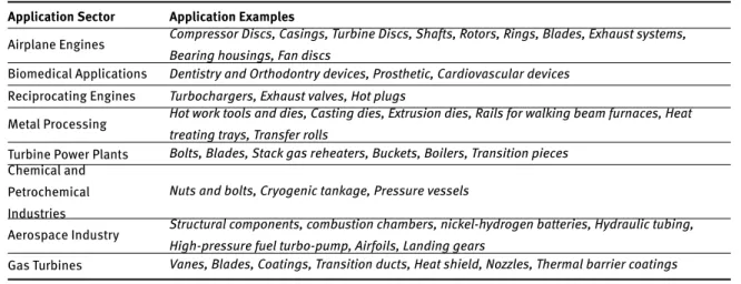
these alloys may be listed as: (1) airplane engine parts, (e.g., compressor discs, turbine discs, shafts, rings, cas-ings and blades), (2) bio-medical applications, (3) recip-rocating engines, (4) metal processing, (5) steam turbine power plants, (6) chemical and petrochemical industries, (7) space vehicles, (8) heat-treating devices, (9) gas tur-bines and (10) coal gasification and liquefaction plants and (11) marine engine parts [1, 2]. A brief overview of superalloys used in these industries are given in Table 1. For instance, 50% weight of a jet engine is Inconel 718 (IN-718), a Ni-Fe-Cr alloy [3]. Some of their unique quali-ties compose their exceptional mechanical properquali-ties such as; high strength, strong oxidation resistance, creep resis-tance, thermal stability, thermal fatigue properties and rel-ative lightness [3, 4]. An overview of some nickel based superalloy parts employed in a jet engine is displayed in Fig. 1.
High-temperature superalloys are mainly classi-fied into three groups: nickel based, cobalt based, and iron-nickel based alloys. Among the super alloys, the most widely used are nickel-based alloys, which contain at least 50% nickel [1]. Two types of strengthening methods are used in these alloys: (1) solid solution strengthening (an-nealing) and (2) precipitation heat treatment (aging). For example, alloys such as INCONEL 718 are precipitation strengthened by𝛾’ (Ni3 [Al, Ti]). Nickel-based alloys are available in cast, wrought and powder metallurgy pro-cessed forms. Rene 95, Udimet 720, and IN100 are exam-ples of produces of powder metallurgy, whereas Rene 80, Mar-M-247, INCONEL 718 and INCONEL 725 are some exam-ples of casting and wrought processing.
Nickel based super alloys display rather difficult machinability characteristics owing to their high temper-ature strength, work hardening tendency and low thermal diffusivity [6]. Like stainless steels, their austenitic matrix is responsible for work hardening during machining. Be-sides, during high machining temperatures, these alloys have affinity to weld with the tool material. The strong tendency to form built up edge (BUE) and the presence of hard intermetallic compounds and abrasive carbides in their microstructure further exacerbate cutting difficul-ties [1]. Another factor negatively affecting the
machinabil-Table 1: A brief overview of applications of superalloys in various industries
Application Sector Application Examples
Airplane Engines Compressor Discs, Casings, Turbine Discs, Shafts, Rotors, Rings, Blades, Exhaust systems, Bearing housings, Fan discs
Biomedical Applications Dentistry and Orthodontry devices, Prosthetic, Cardiovascular devices Reciprocating Engines Turbochargers, Exhaust valves, Hot plugs
Metal Processing Hot work tools and dies, Casting dies, Extrusion dies, Rails for walking beam furnaces, Heat treating trays, Transfer rolls
Turbine Power Plants Bolts, Blades, Stack gas reheaters, Buckets, Boilers, Transition pieces Chemical and
Petrochemical Industries
Nuts and bolts, Cryogenic tankage, Pressure vessels
Aerospace Industry Structural components, combustion chambers, nickel-hydrogen batteries, Hydraulic tubing, High-pressure fuel turbo-pump, Airfoils, Landing gears
Gas Turbines Vanes, Blades, Coatings, Transition ducts, Heat shield, Nozzles, Thermal barrier coatings
Figure 1: Nickel based superalloy positions in a jet engine [5]
ity is the continuous and tough chips produced during ma-chining. Although there are significant improvements in cutting tools, machine control systems, cooling and lubri-cation technology, machining of superalloys is still lead-ing to problems in terms of cuttlead-ing tool wear and surface integrity.
Excessive tool wear is one of the major problems in ma-chining of nickel based superalloys. Because of the low thermal conductivity, most of the heat produced during machining is transferred to the tool. Subsequently, high tool tip temperatures cause excessive tool wear, which can limit cutting speeds and reduce productivity. These tem-peratures can be as high as 1100∘C to 1300∘C, and in turn, may cause severe wear and plastic deformation of the cut-ting tool edge. Tan and Zhang [7] reported that the temper-ature in the cutting region was the main cause of the tool wear in turning of the pure nickel. Hereby, control of tool wear should be ensured through optimum process param-eters, appropriate cutting tool material and geometry.
Surface integrity is another important concern in ma-chining of super alloys and has a direct effect on the qual-ity and performance of a finished product. Qualitative and
quantitative parameters in order to describe and control surface integrity of a surface layer may be listed as follows: mechanical properties (e.g. plastic deformations, hard-ness changes, residual stress distribution and formation of inclusions), metallurgical properties (e.g, transformation of phases, grain size and distribution precipitate size and distribution, twinning, recrystallization and phase trans-formations) and topological features (e.g. surface rough-ness and texture pattern). Surface integrity is one of the most critical parameters in the assessment of the qual-ity of machined parts, especially in aerospace industry, given the fact that the machined part should operate re-liably. The concentrated heat and low temperature gradi-ents also cause microstructural changes forming a white-layer/surface damage within the material in-depth direc-tion, which may cause undesired effects on the perfor-mance of the machined part. Therefore, the surface in-tegrity induced by machining of nickel-based alloys are very critical due to safety and sustainability concerns [5].
The application of superalloys displays a universally increasing trend and machining of them is still a challeng-ing task. Therefore, in machinchalleng-ing of the nickel based su-peralloys, it becomes essential to understand the material removal process and selecting the optimum cutting pa-rameters to meet the desired dimensional accuracy, sur-face quality and sursur-face integrity of the finished product. Many studies have been carried out towards understand-ing the optimum cuttunderstand-ing parameters of nickel-based super-alloys in analytical [8] and simulative approaches [2, 9– 18] as well as experimental [19–31] studies. In those stud-ies, various cutting process parameters (e.g. cutting speed, feed rate and depth of cut) and tool features (e.g. cutting tool material, coating and geometry) were used and the re-sults were reported as machinability characteristics. Ad-ditionally, in the practical machining process,
engineer-ing and technical employee, especially less experienced ones, may prefer staying at the safe side by preferring rather conservative cutting parameters (e.g. speed, feed rate and depth of cut). Thus, a well-explored understand-ing of these parameters are of great importance for fill-ing the gap between science and industry. The aim of this study is to comprehensively review the state-of-the-art nickel based superalloy-machining studies in terms of the following machinability characteristics: tool wear, cutting forces and surface integrity.
2 Tool Wear
Being a major cause of the poor machinability of the superalloys, tool wear is an inevitable process during ma-chining and it progresses until tool life ends. However, should the precaution be taken by knowing the type, rate and timing of the wear, the negativity of the tool wear can be minimized. In terms of productivity, large amount of material removal in a short time interval may be evalu-ated as favorable, whereas a short tool life and early fail-ure of a tool is unfavorable [29]. The resultant tool wear is the composition of mechanical and chemical interac-tions between the tool and the work part during machin-ing. The following wear mechanisms are observed on cut-ting tools of super alloys: adhesive wear, abrasive wear, diffusion wear, oxidation wear and debonding failure [3]. Basic wear causes, mechanisms, types and consequences as well as relationships with other cutting variables are illustrated in Fig. 2. Brief descriptions of metallographic images in Fig. 2, beginning from the left hand-side, are given in the following sentences. In adhesion image, cold welded (adhered) particles of workpiece on the very edge of the cutting tool is displayed. The adhesion generally results from deformations due to high temperature and high pressure as well as chemical reactions of the work-piece and the tool. In the oxidation wear image, rake face of a cutting tool is shown and the related energy spec-trum analysis diagram is shown below. Although, there was coating on tool (Ti, Al and other), none of the coating elements have been found in elemental analysis after cut-ting. This shows that the coating was completely worn due to oxidation wear and the substrate material was exposed to air. In the abrasion image, edge of cutting tools rake face is shown. The groove marks on the face results from the relative motion between the cutting tool and the mate-rial, which causes surface damage. Mainly, hard particles, hard inclusions and thermal softening during cutting are responsible for this wear type. In the debonding image,
Figure 2: A summary of causes, mechanisms, types and
conse-quences of tool wear in nickel based superalloy cutting [3]
a SEM image of a worn cutting insert, whose superficial material was peeled from substrate, is shown. Debonding failure is generally resulted from abrasive wear, adhesive wear, oxidation wear and diffusion wear. In carbide tools, this kind of failure generally forms from adhesive wear and BUE formation; however in ceramic tools, crack initiation is the probable cause. Finally, in diffusion image, face of a cutting tool whose surface was worn due to excessive tem-perature, is shown. During metal cutting, especially met-als like superalloys whose thermal diffusibility is relatively low, rather high temperatures are observed on tool-chip and tool-workpiece interfaces. These high temperatures together with high strain rates, would provide an ideal environment for thermo-chemical reactions, material dis-solving and mass transfer. Wear consequences are briefly summarized at the bottom of Figure 2, where the graph on the left hand side shows that increased wear rate would cause cutting force and temperature increase. On the right hand side, surface quality and geometric-dimensional ac-curacy, all of which are negatively affected from increased wear, are represented.
Cutting speed was reported as one of the most signif-icant parameters of tool wear in machining of the super-alloys [31–36]. D’Addona et al. [37] investigated tool wear and surface roughness in high speed machining of Inconel 718. The researchers used CVD coated carbide inserts at
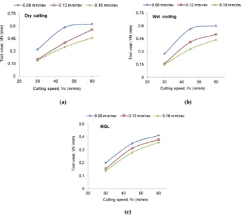
various cutting speeds of 60, 90, 190 and 225 m/min. The depth of cut and the feed rate values were fixed at 0.5 mm and 0.1 mm/rev, respectively. It was reported that the low-est wear was observed at the lowlow-est speed of 60 m/min and the largest at the highest speed of 225 m/min. Thakur et al. [32] carried out a study on high speed turning of In-conel 718 with tungsten carbide (WC) tool with a nose ra-dius of 0.8 mm. The researchers reported that, turning at cutting speed of 45 m/min, feed rate of 0.05 mm/rev and depth of cut value of 0.5 mm, produced tool life of 337 s; whereas increasing of cutting speed to 55 m/min resulted with a tool life of 282 s. The main type of wear was abra-sion and microchipping, besides, some plastic deforma-tion was observed under dry cutting condideforma-tion and BUE formation was unseen for the selected machining parame-ters. Sarikaya et al. [33] investigated wear of uncoated car-bide inserts in turning of Haynes 25 superalloy under four separate cutting speed values (15, 30 , 45 and 60 m/min). It was reported that the wear increases with increasing cut-ting speeds at all feed rate values. This was attributed to increased temperature at tool-chip interface. It was con-cluded that a cutting speed of 30 m/min yielded best tool wear outcome. Influence of cutting speed on notch wear (Vn) under various cutting conditions is given in Fig. 3. In these graphs, it is clear that cutting speed negatively af-fects wear rate under all investigated conditions and wear was acceptable only at 30 m/min cutting speed according to ISO 3685. These findings show that there was a direct re-lationship between tool wear and cutting speed under in-vestigated parameters at constant feed rate. However, con-verse results were also reported by some researchers. An-thony et al. [34] focused on tool life of different tool materi-als under various cutting parameters in turning of Inconel 718. The tool materials were ceramic, PVD TiAlN coated carbide and CBN. The scholars reported that, of the three cutting speeds (60, 90 and 120 m/min), carbide insert ex-perienced higher flank wear at the highest speed and least wear was at 90 m/min. For ceramic tool, however, higher flank wear was observed at low speed (Vc = 60m/min) and with the increase of cutting speed from 90 to 120 m/min there was a decrease in flank wear. As seen in Fig. 4, a decreasing trend was observed in wear curve at increased cutting speeds. Altin et al. [38] investigated wear behav-iors of silicon nitrite based and whisker reinforced ceramic tools in high speed machining of Inconel 718. The experi-ments were conducted under constant feed rate and depth of cut values of 0.20 mm/rev and 2 mm, respectively. The cutting speeds varied between 150 and 300 m/min. It was reported that flank wear, crater and notching formation and plastic deformation were observed as wear behaviors
Figure 3: Notch wear of carbide tools vs cutting speed under some
cutting conditions;a) Dry cutting, b) Wet cooling, c) MQL [33]
and the optimum cutting speed was 250 m/min for both tool materials.
CBN and PCBN tools, having been less frequently pre-ferred in machining of nickel based superalloys, interested some researchers to develop a well explanatory usage of them. Sugihara and Enomoto [23] analyzed the effects of cutting speed on tool surface topography of CBN tools in high speed machining of Inconel 718. The cutting experi-ments were conducted under a wide range of cutting speed values (i.e. 20 - 300 m/min). It was reported that severe adhesion was seen under low cutting speed (i.e. 20 m/s) and diffusion wear was dominant at high cutting speeds (i.e. 100 m/min and 300 m/min). Additionally, crater wear forming was more severe at the highest cutting speed of 300 m/min. Another experimental study was conducted by Khan et al. [39] using PCBN tool in turning of Inconel 718. The researchers investigated effects of cutting speed, feed rate, tool coating, cooling pressure and tool geometry on tool wear. Abrasion driven flank wear was the dominant mode in majority of the tests. Severe BUE and grooving was present at 150 m/min, while at the highest cutting speed of 450 m/min fracture, chipping and thermal cracks were ob-served. The study revealed that the tool life decreased with the increasing cutting speed. However, it was suggested that moderate speed of 300 m/min was the optimum cut-ting speed for productivity and tool wear rate.
The effects of cutting speed on milling process were also investigated. Tian et al. [25] analyzed the effects of cutting speed on tool wear in high-speed face milling of Inconel 718 with SiAlON ceramic tools, using both up and down milling operations. In the study, wide range of
cut-Figure 4: Effect of cutting speed on flank wear in ceramic tools [34]
Figure 5: Flank wear of carbide cutting tools a) speed of 605 RPM,
feed rate of 0.08 mm/rev and b) speed of 421 RPM, feed rate of 0.12 mm/rev [13]
ting speed values (i.e. 600 - 3000 m/min) were experi-mented. The results revealed that notch wear was domi-nant between 600 and 1400 m/min cutting speeds; when the cutting speed was relatively high, between 1800 and 3000 m/min, adhesion wear was the dominant failure type. The researchers reported that, up milling is more suitable for high speed face milling of Inconel 718 with SiAlON ceramic tools to obtain lesser tool wear and longer tool life. It was concluded that a cutting speed under 1000 m/min was not suitable due to severe notch wear. Maiyar et al. [40] conducted a study through optimizing machining parameters for end milling of Inconel 718. In the study, uncoated tungsten carbide tool (10 mm diame-ter, 4 flutes) was used. It was found that, of the three speed values experimented (i.e. 25, 50 and 75 m/min), 75 m/min yielded the best results.
Another major cutting parameter affecting tool wear is feed rate, which has a strong influence on thermo-mechanical properties of chip-tool interaction [41]. Yadav et al. [13] attempted to estimate flank wear and material removal rate in turning of Inconel 718 using chemical va-por deposition (CVD) coated tungsten carbide tool. The re-searchers experimented with four different levels of cut-ting speed, feed rate and depth of cut value. They found that the spindle speed and the depth of cut have significant effect on flank wear (p<0.05). It was reported that feed rate does not have a significant effect on flank wear between values of 0.08 and 0.20 mm/rev. In Fig. 5, it is shown that maximum damage length of flank face has been
consid-ered for assessing the flank wear of tool insert. It is evi-dent from the figure that wear rate does not display a large variation along the cutting edge in Fig. 5a. At a higher feed rate of 0.12 mm/rev, as shown in Fig. 5b, wear land be-comes narrower away from the maximum wear location. However, maximum flank wear values are very close to each other. Conversely, there are studies in which a sig-nificant relationship was observed between feed rate and tool wear. Sarikaya et al. [33] found that, among the three feed rate values (i.e. 0.08, 0.12 and 0.16 mm/rev) in turning with carbide tools, the highest value yielded minimum tool wear when keeping other machining parameters constant. The researchers attributed this to shortened duration of contact between cutting tool and workpiece. In contrast to this result, Davoodi and Eskandri [36] found a signifi-cant relationship between the two variables. In the study, effects of various cutting speed (i.e. 50, 60, 70, 80 and 90 m/min) and feed rate (i.e. 0.100, 0.125, 0.150, 0.175 and 0.200 mm/rev) values on tool life and material removal volume were investigated using response surface method-ology. The cutting insert material was thin TiAlN coated cemented carbide. The results revealed that the increased feed rate values led to higher flank wear rate. It was stated that this result might be attributed to shorter contact area at tool-chip interface, which results in concentration of high temperature close to cutting edge. Influence of feed rate and cutting speed on tool life is shown in Fig. 6. 3D surface graph shows that longest tool life is achieved with the combination of lowest feed rate and cutting speed. Increase of feed rate results in a drastic decrease of tool life. It is also obvious that increase of cutting speed has more influence on reduced tool life. Bushlya et al. [42] re-ported that tool life of PCBN tools showed a reduction of 15% with a feed rate increase of 100%. This tool life re-duction, however, may be neglected, as productivity due to feed rate increment outperforms tool life duration. Lotfi et al. [43] found that ceramic and carbide tools show differ-ent wear behaviors in terms of feed rate-wear relationship. The study showed that, in carbide tools, the effect of feed rate increment (i.e. between 0.1 mm/rev and 0.3 mm/rev) on flank wear was almost insignificant; while wear rate of ceramic tools decreased with increased feed rate (i.e. be-tween 0.07 mm/rev and 0.23 mm/rev).
Cutting tool reinforcement, coating and substrate are other parameters that have a significant influence on tool wear [31, 44–46]. Celik et al. [4] investigated wear be-haviors of solid SiAlON milling tools in high speed milling of Inconel 718. In the study, α/β-SiAlON ceramic tool and its TiN reinforced match were manufactured in solid form with 12 mm diameter. The milling parameters were set as: cutting speed of 585 m/min, radial depth of cut of
Figure 6: Effects of cutting speed and feed rate on tool life [36]
Figure 7: SEM micrographs of the flank faces of the SiAlON and
SiAlON+TiC tools after 12, 24 and 36 min side milling tests [4]
0.635 mm, axial depth of cut of 9.652 mm and feed rate of 0.18 mm/rev. Diffusion based wear emerged as the dom-inant wear mechanism. In addition, a severe adhesion on flank and rake face was seen, as cutting speed was relatively high. As shown in Fig. 7, it was observed that addition of TiN particles into SiAlON matrix had a pos-itive effect on the resistance to the formation of diffu-sion zones. However, it is clear from the figure that wear land (shown with dashed lines) is larger in TiC reinforced SiAlON tool. This occurrence was attributed to the acceler-ation of wear due to low thermal expansion coefficient of possibly formed Al2TiO5with increased titanium. Cantero
et al. [44] tested two different carbide substrates (CP500 and TS2000) with same multilayer coating (inner layer TiAlN and outer layer TiN) in finish turning of Inconel 718. Cutting tests were performed with coolant and dry cutting conditions. It was concluded that substrate CP500 was not appropriate for machining of Inconel 718 due to severe notching wear in all conditions tested.
It is known that surface coatings are used on cut-ting tools in machining of nickel based superalloys in
or-der to improve machinability [44–48]. Coated tools have been reported to display superior wear resistance even at high cutting speeds due to their higher hardness values and lower friction coefficients [45]. Swein et al. [46] in-vestigated machining characteristics of Nimonic 75 using uncoated and TiAlN coated tungsten carbide micro-end mills. The researchers concluded that TiAlN coated tung-sten carbide micro-tools exhibited superior performance as compared to their uncoated counterparts with regard to tool wear under all experimental parameters (i.e. cut-ting speed between 11 and 18 m/min and feed rate be-tween 6 and 8 mm/min). Progress of the tool wear with respect to cutting length is shown Fig. 8 for TiAlN coated and uncoated WC micro-end mills. It is evident from the graph that coated tool displays better wear resistance un-der same cutting conditions. The wear resistance of the coated tool was attributed to the high hardness of the coat-ing as well as formation of Al2O3 oxide layer, which
en-sures a thermal insulation. Ucun et al. [47] investigated the effects of coating material of carbide tools in milling of Inconel 718 under micro conditions. The researchers ex-perimented with five different coating materials such as: TiAlN + AlCrN, DLC, AlTiN, TiAlN,TiAlN + WC/C and Al-CrN. Unsurprisingly, lower levels of wear and diameter changes were observed in coated tools. Particularly, dia-mond like carbon (DLC) coating was suggested for machin-ability characteristics, longer tool life and surface rough-ness. Experimental studies suggested that CBN tools ex-hibit better wear characteristics around 100 m/min cutting speed values [23]. PCBN tools (CBN content being an im-portant parameter of PCBN tools [49]), were reported to perform up to speed values of 1250 m/min [50]. However, Bushlya et al. [42] reported that with the increase of cutting speeds above 300 m/min, coating provides no benefits in PCBN tools. Tanaka et al. [51] concluded that PCBN tools displayed excellent wear resistance at cutting speed over 300 m/min in machining of Inconel 718.
3 Cutting Forces
Cutting forces are of paramount importance as they di-rectly affect power consumption, which, in turn dictates environmental and financial issues [52]. Additionally, it is known that cutting forces are related to other pro-cess outputs such as: residual stress, cutting tempera-ture, wear rate etc. Therefore, cutting force measurements and analyses were conducted by many researchers using dynamometers and FEM simulations respectively. Use of
Figure 8: Progress of tool wear with machining length for TiAlN
coated and uncoated WC micro-end mills [46]
strain gauge to measure cutting forces is another method reported in machining literature [53].
It was reported by various researchers that cutting speed has a significant effect on cutting forces [32, 35]. It is expected that, the cutting forces decrease at higher speeds, as the surface hardness of the workpiece decreases due to increased cutting temperatures (thermal softening). Hao et al. [35] investigated the effects of cutting speed on cutting forces in milling of Inconel 718 with self-reinforced SiAlON ceramic tools. In the study, the experiments were conducted at various cutting speeds (i.e. 50, 100, 200, 250, and 500 m/min) with values of fixed feed engagement per tooth, cutting depth and milling width being 0.09mm/z, 1 mm and 30 mm respectively. In Fig. 9, the influence of cutting speed on cutting forces is displayed. According to this figure, increased cutting speed resulted in decreased cutting force. Here, k shows the slope of the curve between two cutting speeds. The change ratio of the cutting force was greater between 50-100 m/min (k=-3), which may have been caused from rapid decrease of flow stress of the mate-rial due to temperature increase. Thakur et al. [32] carried out a study in high speed turning of Inconel 718 with car-bide tool K20. The researchers reported that, by keeping the feed rate constant at 0.08 mm/rev and maintaining the cutting speed range of 45 to 55 m/min, the principal cut-ting force and the feeding force displayed a linear decline with cutting speed increase. Tian et al. [25] observed that cutting forces were lower between 1400 and 1800 m/min speed range than lower speed values. In turning of In-conel 718 with multilayer coated carbide inserts, Cantero et al. [44] reported a lower cutting force at the speed of 70 m/min than 50 m/min. Parida and Maity [2] reported
Figure 9: Effect of cutting speed on cutting force [35]
that cutting forces decreased when speed was increased from 40 to 100 m/min in machining of Inconel 718. Ezila-rasan et al. [10] concluded that a reduction in tangential cutting force was seen with an increase in cutting speed in turning of Nimonic C-263 super alloy. In accordance with reported results, scholars came to an agreement about cut-ting speed and force relationship.
The resultant cutting force may be explained by simul-taneous effects of mechanical and thermal loads. When using coated tools, lower force due to lower friction coeffi-cient and higher cutting temperatures are expected [42]. Thakur and Gangopadhyay [52] carried out a study to-wards understanding the effects of surface coating on cut-ting forces in machining of Incoloy 825, a nickel based su-peralloy. In the study, uncoated ISO K20 grade cemented carbide grade insert’s performance was compared with its PVD multilayer-coated (TiN/TiAlN) counterpart in both finish and rough machining. Coated tool displayed 40% and 16% lower cutting forces = in comparison with the uncoated match under flooding and minimum quantity lubrication (MQL) conditions, respectively. Özel and Ulu-tan [15] analyzed cutting forces of uncoated and TiAlN coated tungsten carbide tools in turning of IN100 super-alloy. They reported that coated tool resulted with lower cutting forces compared to its uncoated match under low cutting speeds (e.g. 12 m/min). Bushlya et al. [42] inves-tigated effects of cutting conditions on machinability of Inconel 718 during high speed turning with coated (TiN) and uncoated PCBN tools. The parameters used in the study were as follows: cutting speed values of 250, 300 and 350 m/min, feed rate values of 0.1, 0.15 and 0.2 mm/rev and a fixed depth of cut value of 0.3 mm. Surprisingly, the cut-ting forces of coated tools were 10% higher than uncoated matches under all cutting conditions. The researchers
at-Figure 10: Effect of cutting speed on cutting force [35]
tributed this unexpected result to variations in tool micro geometry, as 3-D optical measurements revealed that un-coated tools had edge radius rβ = 15-18 µm, while for un-coated tools rβ = 20-22 µm. Although there is no exact definition for tool micro geometry, the definition generally implies the cutting edge geometry, or edge radius more specifi-cally. As shown in Fig. 10, on the left hand side, although two different tools may seem geometrically identical (e.g. nose radius, rake angle and clearance angle), they might display very distinct cutting performance due to different edge preparation dimensions (Fig. 10 right hand side). A sharper cutting edge would most probably ease cutting, however this would also weaken the tool. For instance, an edge radius of 0.001-0.002 mm would be ideal for soft Al alloys, while 0.020-0.030 mm is preferred for hard to ma-chine alloys such as Ni based superalloys.
4 Surface Integrity
Surface integrity of a machined part has direct effects on operating quality and life of that part. These effects may be summarized as follows [5]: (1) frictional and wear behav-ior at the interfaces of bodies in contact, (2) effectiveness and control of lubrication during processing (e.g. forging, stamping and rolling) and in the final use (e.g. bearing, shafts and all rotating and moving elements), (3) form of the surface in further surface finishing operations, (4) for-mation of micro cracks and residual stresses [54] and (5) heat transfer and electrical conductivity between two bod-ies contacting each other. In the present study, surface in-tegrity is reviewed through two quantitative components: surface roughness and residual stresses.
4.1 Surface Roughness
Surface roughness measurement is one of the most widely used method to quantify the surface integrity of a part. It
has been considered as the primary indicator of the quality of the surface finish, and reported by many scholars in pre-vious studies [25]. Traditional machining processes may not meet desired final surface roughness values in nickel based superalloys. Hence, some surface finishing methods such as ball burnishing may be needed.
Cutting speed has been reported as a substantial deter-minative parameter of surface roughness. Increasing the cutting speed for a better surface roughness is the most widely accepted method in literature [24]. D’Addona et al. [37] analyzed surface quality of Inconel 718 under var-ious cutting speeds (i.e. 60, 90, 190 and 225 m/min) using CVD coated carbide inserts. The results showed that sur-face roughness decreased with increased cutting speeds, except for 225 m/min where surface deterioration was ob-served. The researchers attributed this to notching due to high speeds. Tian et al. [25] analyzed effects of cut-ting speed on surface roughness in high speed milling of Inconel 718 with ceramic tools. In the study, a wide range of cutting speed values were tested (i.e. between 600 and 3000 m/min). It was reported that surface rough-ness displayed a tendency to decrease with increased cut-ting speed, except for V = 3000 m/min. This exception was attributed to the loss of mechanical properties of tools under very high cutting temperatures. In addition, lower surface quality was reported in down milling op-eration, as chip thickness decreases from maximum to zero. Cantero et al. [44] found no significant differences in surface roughness in finish turning of Inconel 718 us-ing speed values of 50 and 70 m/min. The reason of this result may be explained as the use of different cutter tool geometries due to experimental design of the study [39]. Sarikaya and Gullu [33] reported that there was a decreas-ing trend in surface roughness -when increasdecreas-ing cuttdecreas-ing speed in turning of Haynes 25 superalloy. SEM images of the study showed that the increase of cutting speed from 15 m/min to 30 m/min resulted in significantly less ad-hesion in the nose section of the cutting tool. Decreased surface roughness was attributed to this less adhesion for-mation together with reduction of BUE and BUL at higher cutting speeds. Similar results were reported by Maiyar et al. [40]. The researchers reported that 75 m/min cutting speed yielded better results than 25 m/min and 50 m/min speeds in face milling of Inconel 718. The findings of the researchers are in a good agreement with previously re-ported studies as well as common machining practices in industry. The increase of cutting speed have been re-ported to decrease surface roughness. However, increas-ing the cuttincreas-ing speed excessively causes an unfavorable wear, which in turn subjects surface roughness being neg-atively affected. The relationship between cutting speed
and surface roughness for various feed rate values and cut-ting conditions is displayed in Fig. 11. It is obvious from the curves that optimum surface quality is achieved at a cutting speed of 45 m/min under all conditions. Further increasing the cutting speeds results in an increase in sur-face roughness under all conditions and the steepness of the curve being least as in Fig. 11c. This increase proba-bly resulted from accelerated wear of carbide tool due to increased cutting temperatures resulting from increased cutting speed. It should also be noted that the most un-favorable surface quality was, as expected, yielded in dry cutting as seen in Fig. 11a.
Feed rate has been reported as another major param-eter to affect surface roughness in machining of superal-loys [5, 29, 55]. Darwish [55] investigated the effects of var-ious cutting parameters on surface roughness in ing of supermet 718 superalloy. The investigated machin-ing parameters were feed rates between 0.075-0.6 mm/rev, cutting speed of 32 and 125 m/min and depth of cut of 0.5 and 2 mm. The researcher reported that feed rate had the dominant effect on surface quality amongst the pa-rameters studied. The higher feed rate values resulted in higher surface roughness. Similarly, Ezugwu et al. [56] in-vestigated the effects of various cutting parameters on sur-face roughness in machining of Inconel 718. The machin-ing parameters were feed rates of 0.13 and 0.25 mm/rev, cutting speeds of 32 and 50 m/min and depths of cut of 1 and 2 mm. The results showed that increasing the feed from 0.13 to 0.25 mm/rev resulted in significant deterio-ration of the surface, leading to higher surface roughness measurements. Joshi et al. [57] came into agreement with other studies that increasing feed rate makes the surface rougher, after milling UDIMET 720 at cutting speeds of 11 and 56 m/min, feed rates between 0.056 - 0.1 mm/tooth and depth of cut of 0.25 mm. Furthermore, in turning of Rene 41 superalloy, Tali [29] found that increasing feed rate from 0.15 to 0.25 mm/rev increased the surface roughness at speeds of 180 and 240 m/min and depth of cut of 2 mm. The common result of the studies showed that, increasing feed rate negatively affects the surface quality.
4.2 Residual Stress
Residual stress beneath the machined surface is another substantial component of the surface integrity. Follow-ing the machinFollow-ing process, machinFollow-ing induced thermome-chanical loads are released of workpiece. However, some of the load give rise to the subsurface material to keep some stress. This phenomenon is called residual stress. Compressive residual values have been reported to be
fa-Figure 11: Surface roughness results for a) dry cutting b) wet cutting c) MQL [33]
vorable for fatigue performance while tensile values may be detrimental [58, 59], as tensile values may present po-tential risk in terms of crack initiation, propagation and fatigue failure of final products. Therefore, it becomes nec-essary to remove them with additional processes or pre-vent them during machining process. There are many stud-ies towards understanding residual stress mechanisms in machining of nickel based superalloys. Tool micro geome-try and cutting speed are two substantial parameters that have influence on residual stresses.
Edge radius have been reported to have a major ef-fect on residual stresses. Özel and Ulutan [15] conducted experimental investigations and FE simulations on turn-ing of IN100 super alloy usturn-ing uncoated and TiAlNi coated carbide inserts at various edge radius values. It was re-ported that, surface tensile stress showed an increase with increasing edge radius for both radial and circum-ferential directions and coated tool displayed lesser ten-sile residual stress. Bushlya et al. [42] reported similar re-sults. The study revealed that larger subsurface damage (i.e. 800 MPa at 100 µm depth) occurred due to larger edge radius.
Tool nose radius is another geometric feature that have been reported to be an influential geometric param-eter for residual stresses. Sharman et al. [17] investigated the effect of tool nose radius on residual stress in turn-ing of Inconel 718. In the study, variable feed rate values (i.e. 0.25, 0.3, 0.36, 0.42 and 0.50 mm/rev), fixed depth of cut (i.e. 0.25 mm) and cutting speed (i.e. 40 m/min) val-ues were used. The cutter tool was TiCN/Al2O3/TiN
Figure 12: Residual stress profiles of various nose radius values [17]
3 mm, 4 mm and 6 mm. It was reported that larger sur-face tensile stress levels (up to 1550 MPa) and depths (up to 100 µm) were seen with increased tool nose radius. This was attributed to decreased chip thickness at trailing edge, which may subject the material to high pressure and high temperatures. Similarly, Parida and Maity [2] found that in-creased nose radius led to higher effective stresses in cut-ting region. In the study, tungsten carbide tools with nose radius values of 0.4 mm, 0.8 mm and 1.2 mm were used in turning of Inconel 718. The increase of effective stresses were attributed to larger flow of stress due to flank wear for-mation at larger nose radius. In Fig. 12, residual stress mag-nitude and depth from surface for various nose radius and feed rate values are displayed. It can be seen that, in all the cases residual stress varies between 300 and -300 MPa (negative sign being compression). All the profiles follow similar trends (i.e. beginning from maximum stress and reaching a minimum around 50 µm and increasing again, less steep, until 150 µm depth) except for 6 mm nose ra-dius and 0.5 mm/rev feed rate curve. This exception was probably due to very high feed rate value, which causes increased chip thickness and in turn increased plastic de-formation. Bushlya et al. [42], however, reported converse results in terms of nose radius effects on stress levels. The researchers stated that larger nose radius led to decreased chip thickness, which in turn reduced the thermal-related tensile component of the residual stresses as a whole.
The literature study revealed that there is an agree-ment in the effects of cutting speed and feed rate on sub-surface residual stresses. Ezilarasan et al. [10] analyzed the effects of various cutting parameters on effective stresses in machining of Nimonic C-263 superalloy., A maximum ef-fective stress value of 720 MPa was observed at 54 m/min and an increasing trend was displayed with increasing cut-ting speed and feed rate values. Sharman et al. [17] re-ported that for a fixed tool nose radius, increased feed rate
Figure 13: The relationship between cutting speed and residual
stress [60]
caused higher levels of tensile stress and increased ten-sile depth due to increased cutting forces and tempera-tures in the cutting zone. Bushlya et al. [42] found that both, intensity in the deformation zone and thickness of the zone increased with increased cutting speed in high speed turning of Inconel 718. Arunachalam et al. [60] in-vestigated the effects of cutting speed on residual stresses in facing of age hardened Inconel 718. The investigated cutting speed values were between 150 and 450 m/min. The researchers reported that, with the increase of cutting speed, the residual stresses changed from compressive to tensile due to thermal effects of high speed. In Fig. 13, the relationship between cutting speed and residual stress is shown. In this curve, residual stress values change from compressive to tensile at around 250 m/min cutting speed value and display a ramping trend from there. Similar re-sults were reported by Schlauer et al. [61] in turning of In-conel 718 under various cutting parameters (i.e. cutting speeds of 10, 410 and 810 m/min and feed rates of 0.01, 0.06 and 0.11 mm/rev). It was found that tensile residual stresses reached as high as 1300 MPa and minimum resid-ual stresses were measured under lowest cutting speed condition.
5 Conclusions
This paper has reviewed recent studies towards the effects of major cutting parameters on most widely investigated machinability characteristics of nickel based super alloys with the objective of evaluating and discussing different research results. Due to their unique properties and criti-cal usage, there is still room for experimental research for improvements in machining of superalloys,as listed below :
1. Effects of tool micro geometry on various machinabil-ity characteristics including wear rate, cutting forces, surface quality and residual stresses.
In the more recent studies, some researchers tend to experiment with tool micro geometry variables such as edge radius. These variables have been generally neglected, as macro geometric features were accepted to be far more determinative on machinability charac-teristics. However, recent studies show that changes in tool micro geometry may cause surprising results, especially when these micro geometric features are in tool-chip interface.
2. Effects of tool nose radius on tool wear.
Effects of tool nose radius on some machinability char-acteristics such as residual stresses and surface rough-ness have been well studied. In addition, there is a wealth of information on the effects of machining pa-rameters, machining conditions and tool coating on tool wear. While less work has been conducted on the effects of tool nose radius on tool wear.
3. Finding optimum cutting parameters for productivity and surface quality.
There have been a large quantity of studies carried out through understanding the effects of machining parameters on tool wear and cutting forces in the last four decades. Besides, relationship between sur-face integrity and machining parameters has been well studied more recently. However, the results of the studies have shown that there may be a compromise between aggressive cutting parameters (more produc-tivity) and conservative cutting parameters (better quality). It is evaluated that more sophisticated in-vestigations may be carried out for the enlightenment of a well explained optimization of quality and pro-ductivity. In addition, there are still some controver-sial issues on selecting optimum cutting parameters through some machinability characteristics.
4. Effects of insert shape on surface integrity.
It has been shown that insert geometry has a great influence on surface integrity. Accordingly, in vari-ous studies, many geometric variables under fixed cut-ter tool shape have been investigated and significant effects on surface integrity have been reported. Yet, there have been a very limited amount of work con-ducted on the effects of insert shape on surface in-tegrity.
The studies reported in this review have clarified some un-clear issues, however, with the advances in machining and tooling technology, there will be new questions to be in-vestigated in detail. Regarding to evaluation of the recent
studies reviewed in this paper, the following conclusions may be listed.
– Cutting speed stands as the major factor of tool wear in machining of nickel based superalloys. Tool wear rate is higher in areas in which concentrated force and tem-perature is present. This increased temtem-perature neg-atively affects carbide tools, as they are composed of cobalt binders. While in ceramic tools, feed rate in-crease, which causes excessive flank wear, is the lim-iting factor.
– New observations regarding the optimum cutting speed of nickel based superalloys are in good agree-ment with previously reported studies. Experiagree-mental work and simulative analyses have shown that there is an inverse relationship between wear rate and cut-ting speed in ceramic tools, up to a point. In order to achieve maximum productivity for tool wear, ceramic tools’ cutting speed should be set above 250 m/min. For coated carbide tools, however, relatively lower cut-ting speeds, between 40 and 50 m/min are appropri-ate. A lower speed of 30 m/min yields better results in uncoated carbide tools.
– Feed rate is another limiting factor of tool wear. For carbide tools, feed rate values between 2 and 3 mm/rev is recommended. For ceramic tools, lower feed rate values between 1 and 2.5 mm/rev is preferable. – The diverse results of carbide and ceramic tools’
cut-ting parameters arise from different thermal and me-chanical properties of the two materials.
– Being another cutter material used in nickel alloy ma-chining, CBN tools work best at 100 m/min cutting speeds, and PCBN tools are better at 300 m/min speed without additional concerns. However, these mate-rials are relatively more expensive than the carbide tools. Additionally, in some machining conditions, they may provide worser results compared to those of the carbide tools.
– There is an inverse relationship between cutting speed and cutting forces. This was attributed to thermal soft-ening of the work material under higher speed val-ues. In addition, selection of coated inserts yielded de-creased cutting forces.
– Larger tool radius is favorable in terms of productiv-ity; however, the analysis of the studies revealed that larger nose radius led to increased residual stresses. Therefore, in machining of the final surface, size of the tool nose should be kept under control due to residual stress concerns.
– Tool edge radius is another significant parameter for residual stresses. Increase of edge radius values yielded larger residual stresses. A better
understand-ing of this relationship would render it possible to achieve better surface and subsurface quality. – Increase of cutting speed and feed rate is
detrimen-tal to residual stress magnitudes and depth due to in-creased cutting temperatures at the cutting zones.
Acknowledgement: Both of the authors listed in the cover
page have made substantial contributions to the present study.
This research did not receive any specific grant from funding agencies in the public, commercial, or not-for-profit sectors.
The present paper has not been published elsewhere and it has not been submitted simultaneously for publica-tion elsewhere.
References
[1] Choudhury IA, El-Baraide MA. Machinability of nickel-base su-per alloys: a general review. Journal of Materials Processing Technology 1998; 77:278-284.
[2] Parida AK, Maity K. Effect of nose radius on forces and process parameters in hot machining of Inconel 718 using finite element analysis. Engineering Science and Technology, an International Journal 2017; 20:687-693.
[3] Zhu D, Zhang X, Ding H. Tool wear characteristics in machining of nickel-based superalloys. International Journal of Machine Tools & Manufacture 2013; 64:60-77.
[4] Çelik A, Alağaç MS, Turan S, Kara A, Kara F. Wear Behavior of solid SiAlON milling tools during high speed milling of Inconel 718. Wear 2017; 378-379:58-67.
[5] Ulutan D, Ozel T. Machining induced surface integrity in tita-nium and nickel alloys: a review. International Journal of Ma-chine Tools and Manufacture 2011; 51:250–280.
[6] Imran M, Mativenga PT, Gholinia A, Withers PJ. Comparison of tool wear mechanisms and surface Integrity for dry and wet mi-cro drilling of nickel-base superalloys. International Journal of Machine Tools & Manufacture 2014; 76:49-60.
[7] Tan MT, Zhang ZY. Groove wear of tools in NC turning of pure nickel. CIRP Annals - Manufacturing Technology 1986; 35(1):71– 74.
[8] Euan IG, Ozturk E, Sims ND. Modeling static and dynamic cutting forces and vibrations for inserted ceramic milling tools. Proce-dia CIRP 2013; 8:564-569.
[9] Lotfi M, Jahanbakhsh M, Farid AA. Wear estimation of ceramic and coated carbide tools in turning of Inconel 625: 3D FE analy-sis. Tribology International 2016; 99:107-116.
[10] Ezilarasan C, Kumar VS, Velayudham A. Theoretical predictions and experimental validations on machining the Nimonic C-263 super alloy. Simulation Modelling Practice and Theory 2014; 40:192-207.
[11] Kagnaya T, Lambert L, Lazard M, Boher C, Cutard T. Investiga-tion and FEA based simulaInvestiga-tion of tool wear geometry and metal oxide effect on cutting process variables. Simulation Modelling Practice and Theory 2014; 42:84–97.
[12] Binder M, Klocke F, Lung D. Tool wear simulation of complex shaped coated cutting tools. Wear 2015; 332:600–607. [13] Yadav RK, Abhishek K, Mahapatra SS. A simulation approach
for estimating flank wear and material removal rate in turning of Inconel 718. Simulation Modelling Practice and Theory 2015; 52:1-14.
[14] Hokka M, Gomon D, Shrot A, Leemet T, Bäker M, Kuokkala VT. Dynamic behavior and high speed machining of Ti-6246 and Al-loy 625 super alAl-loys: experimental and modeling approaches. Experimental Mechanics 2014; 54(2):199–210.
[15] Özel T, Ulutan D. Prediction of machining induced residual stress in turning of titanium and nickel based alloys with exper-iments and finite element simulations. CIRP Annals - Manufac-turing Technology 2012; 61:547-550.
[16] Xi Y, Bermingham M, Wang G, Dargusch M. FEA modelling of cut-ting force and chip formation in thermally assisted machining of Ti6Al4V alloy. Computational Materials Science 2013; 84:188– 197.
[17] Sharman ARC, Hughes JI, Ridgway K. The effect of tool nose ra-dius on surface integrity and residual stresses when turning Inconel 718. Journal of Materials Processing Technology 2015; 216:123-132.
[18] Caruso S, Imbrogno S, Rotella G, Ciaran MI, Arrazola PJ, Filice L et al. Numerical simulation of surface modification during ma-chining of nickel based superalloy. Procedia CIRP 2015; 31:130-135.
[19] Uhlmann E, Kaulfersch F, Roeder M. Turning of high-performance materials with rotating indexable inserts. Precedia CIRP 2014; 14:610-615.
[20] Obikawa T, Yamaguchi M. Suppression of notch wear of a whisker reinforced ceramic tool in air-jet-assisted high speed machining of Inconel 71. Precision Engineering 2015; 39:143-151.
[21] Lima FF, Sales WF, Costa ES, da Silva FJ, Machado AAR. Wear of ceramic tools when machining Inconel 751 using argon and oxy-gen as lubri-cooling atmospheres. Ceramics International 2017; 43:677-685.
[22] Thakur A, Gangopadhyay S, Maity KP. Effect of cutting speed and tool coating on machined surface integrity of Ni-based super al-loy. Procedia CIRP 2014; 14:541-545.
[23] Sugihara T, Enomoto T. High speed machining of Inconel 718 fo-cusing on tool surface topography of CBN tool. Procedia Manu-facturing 2015; 1:675-682.
[24] Sarikaya M, Gullu M. Taguchi design and response surface methodology based analysis of machining parameters in CNC turning under MQL. Journal of Cleaner Production 2014; 65:604-616.
[25] Tian X, Zhao J, Zhao J, Gong Z, Dong Y. Effect of cutting speed on forces and wear mechanisms in high-speed face milling of Inconel 718 with Sialon ceramic tools. Int J Adv Manuf Technol 2013; 69:2669-2678.
[26] Polvorosa R, Suarez A, de Lacalle LNL, Cerillo I, Wretland A, Veiga F. Tool wear on nickel alloys with different coolant pres-sures: Comparison of Alloy 718 and Waspalloy. Journal of Man-ufacturing Processes 2017; 36:44-56.
[27] Hood R, Morris J, Soo SL. Workpiece integrity when milling Udimet 720 superalloy. Procedia CIRP 2016; 45:283-286. [28] Nath C, Brooks Z, Kurfess TR. Machinability study and process
optimization in face milling of some super alloys with indexable copy face mill inserts. Journal of Manufacturing Processes 2015;
20:88-97.
[29] Tali D., Machinability of Rene 41 Superalloy on Different Turn-ing Parameters, PhD Thesis, Eskişehir Osmangazi University, Eskisehir, Turkey, 2016
[30] Çolak O. Investigation on machining performance of Inconel 718 under high pressure cooling conditions. Strojniški vestnik -Journal of Mechanical Engineering 2012; 58(11):683-690. [31] Ezugwu EO, Okeke CI. Performance of PVD coated carbide
in-serts when machining a nimonic (C-263) alloy at high speed con-ditions. Tribology Transactions 2000; 43(2):332-336.
[32] Thakur DG, Ramamoorthy B, Vijayaraghavan L. Study on the machinability characteristics of superalloy Inconel 718 during high speed turning. Materials and Design 2009; 30(5):1718– 1725.
[33] Sarikaya M, Yılmaz V, Güllü A. Analysis of cutting parameters and cooling/lubrication methods for sustainable machining in turning of Haynes 25 superalloy. Journal of Cleaner Production 2016; 133:172-181.
[34] Anthony XM, Manohar M, Jeyapandiarajan P, Madhukar PM, Tool wear assessment during machining of Inconel 718. Procedia En-gineering 2017; 174:1000-1008.
[35] Hao Z, Fan Y, Lin J, Ji F, Liu X. New observations on wear mecha-nism of self-reinforced SiAlON ceramic tool in milling of Inconel 718. Archives of Civil and Mechanical Engineering 2017; 17:467-474.
[36] Davoodi B, Eskandri B. Tool wear mechanisms and multi-response optimization of tool life and volume of material re-moved in turning of N-155 iron–nickel-base superalloy using RSM. Measurement 2015; 68:286-294.
[37] D’Addonaa DM, Raykarb SJ, Narke MM. High speed machining of Inconel 718: tool wear and surface roughness analysis. Procedia CIRP 2017; 62:269-274.
[38] Altin A, Nalbant M, Taskesen A. The effects of cutting speed on tool wear and tool life when machining Inconel 718 with ceramic tools. Materials and Design 2007; 28(9):2518-2522
[39] Khan SA, Soo SL, Aspinwall DK, Sage C, Harden P, Fleming M, White A, Saoubi RM. Tool wear/life evaluation when finish turn-ing Inconel 718 usturn-ing PCBN toolturn-ing. Procedia CIRP 2012; 1:283-288.
[40] Maiyar LM, Ramanujam R, Venkatesan K, Jerald J. Optimization of machining parameters for end milling of Inconel 718 super alloy using Taguchi Based Grey Relation Analysis. Procedia En-gineering 2013; 64:1276-1282.
[41] Shaw MC. Metal Cutting Principles. In: Shear Strain in Steady State Cutting. 2nd ed. New York: Oxford University Press; 2005. [42] Bushlya V, Zhou J, Ståhl JE. Effect of cutting conditions on machinability of superalloy Inconel 718 during high speed turn-ing with coated and uncoated PCBN tools. Procedia CIRP 2012; 3:370-375.
[43] Lotfi M, Jahanbakhsh M, Farid AA. Wear estimation of ceramic and coated carbide tools in turning of Inconel 625: 3D FE analy-sis. Tribology International 2016; 99:107-116.
[44] Cantero JL, Diaz-Alvarez J, Miguelez MH, Marin NC. Analysis of tool wear patterns in finishing turning of Inconel 718. Wear 2013; 297:885-894.
[45] Bhatt A, Attia H, Vargas R, Thomson V. Wear mechanisms of WC coated and uncoated tools in finish turning of Inconel 718. Tri-bology International 2010; 43:1113–1121.
[46] Swain N, Venkatesh V, Kumar P, Srinivas G, Ravishankar S, Barshilia HC. An experimental investigation on the machining
characteristics of Nimonic 75 using uncoated and TiAlN coated tungsten carbide micro-end mills. CIRP Journal of Manufactur-ing Science and Technology 2017; 16:34-42.
[47] Ucun İ, Aslantas K, Bedir F. An experimental investigation of the effect of coating material on tool wear in micro milling of Inconel 718 super alloy. Wear 2013; 300:8-19.
[48] Mindivan F, Mindivan H. Comparisons of wear performance of hardened Inconel 600 by different nitriding processes. Procedia Engineering 2013; 68:730-735.
[49] Matsuda Y, Okamura K, Uesaka S, Fukaya T. Development of new grade “SUMIBORON BN7000” for cast iron and ferrous powder metal machining. SEI Technical Review 2012; 75:13-17. [50] Uhlmann E, Ederer G. High speed turning of Inconel 718.
Indus-trial Diamond Review 2001; 61(590):169-174.
[51] Tanaka H, Sugihara T, Enomoto T. High speed machining of In-conel 718 focusing on wear behaviors of PCBN cutting tool. Pro-cedia CIRP 2016; 46:545-548.
[52] Thakur A, Gangopadhyay S. Dry machining of nickel-based su-per alloy as a sustainable alternative using TiN/TiAlN coated tool. Journal of Cleaner Production 2016; 129:256-268. [53] Akyüz B. Comparison of the machinability and wear
proper-ties of magnesium alloys. The International Journal of Advanced Manufacturing Technology 2014; 75(9):1735-1742.
[54] Ghanem F, Braham C, Fitzpatrick ME, Sidhom H. Effect of near-surface residual stress and microstructure modification from machining on the fatigue endurance of a tool steel. Journal of Materials Engineering and Performance 2002; 11(6):631–639. [55] Darwish SM. The impact of tool material and the cutting
param-eters on surface roughness of supermet 718 nickel superalloy. Journal of Materials Processing Technology 2000; 97:10–18. [56] Ezugwu EO, Wang ZM, Okeke CI. Tool life and surface integrity
when machining Inconel 718 with PVD and CVD coated tools. Tribology Transactions 1999; 42(2):353–360.
[57] Joshi SV, Vizhian SP, Sridhar BR, Jayaram K. Parametric study of machining effect on residual stress and surface roughness of nickel base super alloy UDIMET 720. Advanced Materials Re-search 2008; 47–50:13-16.
[58] M’Saoubi R, Axinte D, Soo SL, Nobel C, Attia H, Kappmeyer G, En-gin S, Sim W. High performance cutting of advanced aerospace alloys and composite materials. CIRP Annals - Manufacturing Technology 2015; 64:557-580.
[59] Dudzinski D, Devillez A, Moufki A, Larrouquerre D, Zerrouki V, Vi-gneau J. A review of developments towards dry and high speed machining of Inconel 718 alloy. International Journal of Machine Tools and Manufacture 2004; 44(4):439–456.
[60] Arunachalam RM, Mannan MA, Spowage AC. Residual stress and surface roughness when facing age hardened Inconel 718 with CBN and ceramic cutting tools. International Journal of Ma-chine Tools and Manufacture 2004; 44:879–887.
[61] Schlauer C, Peng RL, Oden M. Residual stresses in a nickel-based superalloy introduced by turning. Material Science Forum 2002; 404–407:173–178.

![Figure 4: Effect of cutting speed on flank wear in ceramic tools [34]](https://thumb-eu.123doks.com/thumbv2/9libnet/4004614.54797/5.892.112.419.102.249/figure-effect-cutting-speed-flank-wear-ceramic-tools.webp)
![Figure 6: Effects of cutting speed and feed rate on tool life [36]](https://thumb-eu.123doks.com/thumbv2/9libnet/4004614.54797/6.892.85.411.93.363/figure-effects-cutting-speed-feed-rate-tool-life.webp)

![Figure 10: Effect of cutting speed on cutting force [35]](https://thumb-eu.123doks.com/thumbv2/9libnet/4004614.54797/8.892.76.421.95.263/figure-effect-cutting-speed-cutting-force.webp)
![Figure 11: Surface roughness results for a) dry cutting b) wet cutting c) MQL [33]](https://thumb-eu.123doks.com/thumbv2/9libnet/4004614.54797/9.892.464.814.92.408/figure-surface-roughness-results-dry-cutting-cutting-mql.webp)
![Figure 12: Residual stress profiles of various nose radius values [17]](https://thumb-eu.123doks.com/thumbv2/9libnet/4004614.54797/10.892.447.794.106.288/figure-residual-stress-profiles-various-nose-radius-values.webp)
