Abstract—Patients with deep brain stimulation (DBS) implants are often denied access to magnetic resonance imaging (MRI) due to safety concerns associated with RF heating of implants. Although MR-conditional DBS devices are available, complying with manufacturer guidelines has proved to be difficult as pulse sequences that optimally visualize DBS target structures tend to have much higher specific absorption rate (SAR) of radiofrequency energy than current guidelines allow. The MR-labeling of DBS devices, as well as the majority of studies on RF heating of conductive implants have been limited to horizontal close-bore MRI scanners. Vertical MRI scanners, originally introduced as open low-field MRI systems, are now available at 1.2 T field strength, capable of high-resolution structural and functional imaging. No literature exists on DBS SAR in this class of scanners which have a 90 rotated transmit coil and thus, generate a fundamentally different electric and magnetic field distributions. Here we present a simulation study of RF heating in a cohort of forty patient-derived DBS lead models during MRI in a commercially available vertical open-bore MRI system (1.2 T OASIS, Hitachi) and a standard horizontal 1.5 T birdcage coil. Simulations were performed at two major imaging landmarks representing head and chest imaging. We calculated the maximum of 0.1g-averaged SAR (0.1g-SARMax) around DBS lead tips when a B1+ = 4 T was
generated on an axial plane passing through patients body. For head landmark, 0.1g-SARMax reached 220188 W/kg in the 1.5 T
birdcage coil, but only 1411 W/kg in the OASIS coil. For chest landmark, 0.1g-SARMax was 2417 W/kg in the 1.5 T birdcage
coil and 32 W/kg in the OASIS coil. A paired two-tail t-test revealed a significant reduction in SAR with a large effect-size during head MRI (p < 1.510-8, Cohen’s d = 1.5) as well as chest
MRI (p < 6.510-10, Cohen’s d = 1.7) in 1.2 T Hitachi OASIS coil
compared to a standard 1.5 T birdcage transmitter. Our findings suggest that open-bore vertical scanners may offer an untapped opportunity for MRI of patients with DBS implants.
I. INTRODUCTION
Deep brain stimulation (DBS) is the neurosurgical procedure of choice for treating several major neurological and psychiatric disorders, which uses an implantable pulse generator (IPG) in patient’s chest to deliver electrical pulses to specific nuclei in the brain via subcutaneous leads and extensions. Patients with DBS implants can significantly *This work was supported by the NIH grants R00EB021320 and R03EB025344.
Corresponding Author: Laleh Golestanirad email: [email protected]
1Department of Radiology, Feinberg School of Medicine, Northwestern University, Chicago, Illinois, USA, 2Department of Electrical and Electronics Engineering, Bilkent University, Ankara, Turkey, 3National Magnetic Resonance Research Center (UMRAM), Bilkent University, Ankara, Turkey,
benefit from magnetic resonance imaging (MRI), both for electrode localization and for monitoring of stimulation-induced changes in function of brain networks. Unfortunately, however, MRI is often inaccessible to these patients due to the interaction between RF fields of the MRI scanner and DBS leads causing safety concerns associated with RF heating of implants [1]. As a result, conditions under which MRI is indicated for DBS patients are restrictive: only 1.5 T horizontal scanners are allowed and only pulse sequences with highly reduced power (whole-head SAR of <0.1 W/kg - 30 times lower than the FDA limit, or rmsB1+ field < 2 μT) are recommended.
To date, the majority of MRI safety studies have been performed on horizontal closed-bore MRI systems. Vertical scanners, originally introduced as low-field open-bore systems, are now available at high field strength capable of high-resolution structural and functional studies. No literature (except our recent work [2]) exists on RF heating of DBS implants inside this class of scanners which have a 90 rotated transmit coil and thus generate a fundamentally different distribution of electric and magnetic fields inside patient’s body. As the orientation and phase of MRI incident electric field along the trajectory of an elongated implant has a substantial effect on the local SAR at the electrode tips [1, 3-8], we hypothesized that vertical scanners generate a statistically different RF heating compared to horizontal systems. Our hypothesis is based on a preliminary study of RF heating of DBS implants in three (3) realistic patient models which showed 4- to 14-fold reduction in the maximum local SAR around DBS electrodes in a vertical 1.2 T coil compared to a horizontal 1.5 T coil [2]. Here we extend our previous work to include a cohort of 20 patient models with bilateral DBS leads (40 lead models in total) with realistic trajectories. We also investigated the effect of imaging landmark on RF heating in both coils.
II. METHODS
A. RF coil models
Numerical models of a 1.2 T high-pass radial planar birdcage coil made of 12 vertical rungs, and a 1.5 T high-pass birdcage coil consisting of 16 horizontal rungs were 4Department of Biomedical Engineering, McCormick School of Engineering, Northwestern University, Evanston, Illinois, USA, 5A. A. Martinos Center for Biomedical Imaging, Massachusetts General Hospital, Boston, Massachusetts, USA, 6Department of Physical Therapy and Human Movement Sciences, Feinberg School of Medicine, Northwestern University, 7Department of Neurological Surgery, Feinberg School of Medicine, Northwestern University, Chicago, Illinois, USA,
RF heating of deep brain stimulation implants during MRI in 1.2 T
vertical scanners versus 1.5 T horizontal systems: A simulation study
with realistic lead configurations
Ehsan Kazemivalipour
1,2,3, Jasmine Vu
1,4, Stella Lin
1, Bhumi Bhusal
1, Bach Thanh Nguyen
1, John
Kirsch
5, Behzad Elahi
6, Joshua Rosenow
7, Ergin Atalar
2,3, and Laleh Golestanirad
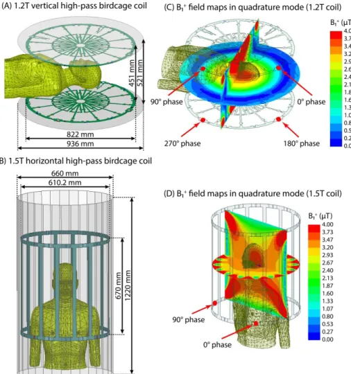
1,4constructed and tuned to their respective Larmor frequencies (50.35 MHz for proton imaging at 1.2 T and 64 MHz for 1.5 T). The vertical coil was modeled to mimic Hitachi OASIS system. Fig. 1 shows the geometrical details of both coil models and their B1+ field maps on the central coronal and
axial planes passing through a human body model with no implant. Horizontal birdcage coil dimensions were chosen similar to those reported in the literature [9]. The vertical coil was derived by four feeding ports arranged in the upper and lower segments, based on information provided by the manufacturer. Both coils were derived in the quadrature excitation mode by feeding their ports with the same amplitudes and different phases as shown in Fig. 1. The body model was placed in two different positions within the coils to mimic head and chest imaging landmarks (Fig. 2).
B. Patient-derived DBS lead models and numerical simulations
We simulated 40 DBS lead models with realistic trajectories based on postoperative computed tomography (CT) images from 20 patients with bilateral DBS leads. Northwestern University's ethics review board approved the prospective use of imaging data for modeling and simulation. The 3D implant models were constructed utilizing a similar process outlined in our previous works [5, 10, 11]. The implant details as used in numerical simulations are shown in Fig. 3.
Each lead was modeled as a solid straight platinum‐iridium (Pt:Ir) core (diameter = 0.5 mm, σ = 4 × 10
6 S/m) embedded
into a urethane insulation (diameter = 1 mm, 𝜀𝑟 = 3.5) with a
Fig. 2 - Geometry configuration of (A) 1.2 T high-pass radial planar birdcage coil and (B) 1.5 T high-pass birdcage coil. (C-D)
B1+ field maps on the central coronal and
axial planes passing through the human body model with no implants. The input power of coils is adjusted to generate a
mean B1+ = 4 μT over a circular plane
placed on an axial plane passing through coils’ iso-center.
Fig. 1 - Coil configuration of 1.2 T vertical and 1.5 T horizontal coils loaded with a human body model placed at two different positions corresponding to head and chest imaging.
2mm exposed tip. Lead models were registered to a standard homogeneous head and torso model (σ = 0.47 S/m, 𝜀𝑟 = 80).
All simulations were implemented in ANSYS Electronic Desktop 19.2 (ANSYS Inc., Canonsburg, PA). For each simulation, the input power of coils was adjusted to produce a mean B1+ = 4 μT over a circular plane with a diameter of 48 mm positioned inside the body model on an axial plane passing through coil’s iso-center. The maximum of 0.1g-averaged SAR (0.1g-SARmax) was calculated inside a cubic area of 202020 mm3 surrounding the tip of the lead. Upon numerical convergence, the computing space had roughly 4.6 and 4 million tetrahedral meshes in vertical and horizontal cases, respectively. The computation time on a Dell PowerEdge R740xd system with 1.5 TB RAM and two Intel(R) Xenon(R) Gold 6140 CPUs (2.3 GHz, 36 cores) was ~12 hours and ~4 hours, for each case respectively.
III. RESULTS
Fig. 4 shows the distribution of local SAR for the patient who showed the highest value of 0.1g-SARmax among all
patients, for both vertical and horizontal coils and at both imaging landmarks (ID11). For the head (chest) landmark, the 0.1g-SARmax around the tips of left and right leads were reduced by 27-fold (9-fold) and 16-fold (10-fold), respectively, in the vertical coil compared to the horizontal coil. Fig. 5 depicts box plot of the 0.1g-SARmax over all 40 lead models. For the head landmark, the 0.1g-SARmax was 1411 W/kg for the OASIS vertical coil and 220188 W/kg for the horizontal birdcage coil. At the chest landmark, the 0.1g-SARmax was 32 W/kg for the OASIS coil and 2417 W/kg for the horizontal birdcage. A paired two-tail t-test showed a significant reduction in SAR with a large effect-size during head MRI (p < 1.510-8, Cohen’s d = 1.5) as well as chest MRI (p < 6.510-10, Cohen’s d = 1.7) in 1.2 T Hitachi OASIS coil compared to a standard 1.5 T birdcage transmitter.
IV. DISCUSSION AND CONCLUSIONS
Over the past decade, DBS has evolved to a remarkable treatment for a variety of mental and neurological disorders. MRI is extremely useful in patients with DBS implants both for electrode localization and ruling out complications, and for evaluating the stimulation’s therapeutic effects. The key impediment for these patients to benefit from MRI is the RF
Fig. 4 - Local SAR distributions in patient 11 (ID11) for the 1.2 T vertical and 1.5 T horizontal coils both with head and chest landmarks on an axial plane that passes through the tips of implants. The input power of coils is
adjusted to generate a mean B1+ = 4μT over a circular plane placed on an
axial plane passing through coils’ iso-center.
Fig. 5 - Local 0.1g-SARmax over 40 leads shown for the 1.2 T vertical and 1.5
T horizontal coils for head and chest landmarks. The outliers were plotted individually using a red ‘+’ symbol.
Fig. 3 – (A) Examples of post-operative CT images of
three patients (patient
numbers ID1-ID3). (B)
Reconstructed models of isolated DBS leads. Lead trajectories were extracted using CT images of 20 patients with bilateral DBS
implantation (patient
numbers ID1-ID20) and were registered in a homogenous
body phantom for
electromagnetic simulations.
heating due to the interaction between RF fields of the MR scanner and DBS leads and extensions. Recent years have witnessed a spike in attempts to mitigate the problem of MRI-induced implant heating. Most of these efforts have focused to modify the geometry, structure or material of implants to suppress induced currents [12-14] or to alter the MRI hardware to reduce its interaction with the implant [4, 11, 15-28].
The existing literature on MRI RF safety as well as MR-labeling of DBS devices are limited to horizontal closed-bore MRI scanners. Vertical MRI systems which produce a substantially different distribution of magnetic and electric fields have not been studied in the context of RF heating of implants. Our work presents the first finite element simulation study of DBS device RF heating in a relatively large sample (N = 40) of patient-derived realistic lead models to compare RF heating in labeled 1.5 T systems and currently unlabeled vertical 1.2 T vertical scanners. On average, we found that 0.1g-averaged SAR was reduced by 16-fold for head imaging and by 8-fold for chest imaging in MRI with a 1.2 T vertical coil compared to a standard 1.5 T horizontal body coil. Interestingly, vertical scanners were originally developed to facilitate open-access to patient and thus, provide an ideal platform for image-guided DBS surgery. These results, if verified in experiments, can open the door to a plethora of MRI applications to guide and interpret DBS therapy.
REFERENCES
[1] A. R. Rezai et al., "Neurostimulation system used for deep brain stimulation (DBS): MR safety issues and implications of failing to follow safety recommendations," Invest Radiol, vol. 39, no. 5, pp. 300-303, May 2004, doi: 10.1097/01.rli.0000124940.02340.ab.
[2] L. Golestanirad et al., "RF heating of deep brain stimulation implants in open-bore vertical MRI systems: A simulation study with realistic device configurations," Magn Reson Med, Nov 2 2019, doi: 10.1002/mrm.28049.
[3] C. J. Yeung, R. C. Susil, and E. Atalar, "RF heating due to conductive wires during MRI depends on the phase distribution of the transmit field," Magn Reson Med, vol. 48, no. 6, pp. 1096-1098, Dec 2002, doi: 10.1002/mrm.10310.
[4] Y. Eryaman, B. Akin, and E. Atalar, "Reduction of Implant RF Heating Through Modification of Transmit Coil Electric Field," Magn Reson
Med, vol. 65, no. 5, pp. 1305-1313, May 2011, doi: 10.1002/mrm.22724.
[5] L. Golestanirad et al., "RF-induced heating in tissue near bilateral DBS implants during MRI at 1.5T and 3T: The role of surgical lead management," Neuroimage, vol. 184, pp. 566-576, Jan 1 2019, doi: 10.1016/j.neuroimage.2018.09.034.
[6] L. Golestanirad et al., "Changes in the specific absorption rate (SAR) of radiofrequency energy in patients with retained cardiac leads during MRI at 1.5T and 3T," Magn Reson Med, vol. 81, no. 1, pp. 653-669, Jan 2019, doi: 10.1002/mrm.27350.
[7] L. Golestanirad et al., "Local SAR near deep brain stimulation (DBS) electrodes at 64 MHz and 127 MHz: A simulation study of the effect of extracranial loops " Magn Reson Med, vol. 88, no. 4, pp. 1558-1565, 2016.
[8] L. Golestanirad et al., "Variation of RF heating around deep brain stimulation leads during 3.0 T MRI in fourteen patient-derived realistic lead models: The role of extracranial lead management," Proc. Intl. Soc.
Magn Reson Med 25 2017.
[9] Yeo DT, Wang Z, Loew W, Vogel MW, and H. I, "Local SAR in High Pass Birdcage and TEM Body Coils for Multiple Human Body Models in Clinical Landmark Positions at 3T," J Magn Reson Imaging, vol. 33(5), pp. 1209–1217, 2011 May, doi: 10.1002/jmri.22544.
[10] L. Golestanirad et al., "Local SAR near deep brain stimulation (DBS) electrodes at 64 and 127 MHz: A simulation study of the effect of extracranial loops," Magn Reson Med, vol. 78, no. 4, pp. 1558-1565, Oct 2017, doi: 10.1002/mrm.26535.
[11] C. E. McElcheran et al., "Numerical Simulations of Realistic Lead Trajectories and an Experimental Verification Support the Efficacy of
Parallel Radiofrequency Transmission to Reduce Heating of Deep Brain Stimulation Implants during MRI," Sci Rep-Uk, vol. 9, Feb 14 2019, doi: ARTN 212410.1038/s41598-018-38099-w.
[12] S. McCabe and J. Scott, "A Novel Implant Electrode Design Safe in the RF Field of MRI Scanners," IEEE T Microw Theory, vol. 65, no. 9, pp. 3541-3547, Sep 2017, doi: 10.1109/Tmtt.2017.2669977.
[13] L. Golestanirad et al., "Reducing RF-Induced Heating Near Implanted Leads Through High-Dielectric Capacitive Bleeding of Current (CBLOC)," IEEE T Microw Theory, vol. 67, no. 3, pp. 1265-1273, Mar 2019, doi: 10.1109/Tmtt.2018.2885517.
[14] P. Serano, L. M. Angelone, H. Katnani, E. Eskandar, and G. Bonmassar, "A Novel Brain Stimulation Technology Provides Compatibility with MRI," Sci Rep-Uk, vol. 5, Apr 29 2015, doi: ARTN 980510.1038/srep09805.
[15] C. E. McElcheran, B. S. Yang, K. J. T. Anderson, L. Golenstani-Rad, and S. J. Graham, "Investigation of Parallel Radiofrequency Transmission for the Reduction of Heating in Long Conductive Leads in 3 Tesla Magnetic Resonance Imaging," Plos One, vol. 10, no. 8, Aug 3 2015, doi: ARTN e013437910.1371/journal.pone.0134379. [16] C. E. McElcheran, B. S. Yang, K. J. Anderson, L. Golestanirad, and S.
J. Graham, "Parallel radiofrequency transmission at 3 tesla to improve safety in bilateral implanted wires in a heterogeneous model," Magn
Reson Med, vol. 78, no. 6, pp. 2406-2415, Dec 2017, doi:
10.1002/mrm.26622.
[17] Y. Eryaman et al., "Parallel Transmit Pulse Design for Patients with Deep Brain Stimulation Implants," Magn Reson Med, vol. 73, no. 5, pp. 1896-1903, May 2015, doi: 10.1002/mrm.25324.
[18] B. Guerin, L. M. Angelone, D. Dougherty, and L. L. Wald, "Parallel transmission to reduce absorbed power around deep brain stimulation devices in MRI: Impact of number and arrangement of transmit channels," Magn Reson Med, Aug 7 2019, doi: 10.1002/mrm.27905. [19] P.-S. Wei, B. Yang, C. McElcheran, L. Golestanirad, and S. J. Graham,
"Reducing Radiofrequency-induced Heating in Realistic Deep Brain Stimulation Lead Trajectories using Parallel Transmission," Proc. Int.
Soc. Magn. Reson. Med., vol. 26, 2018.
[20] C. McElcheran, L. Golestanirad, and S. Graham, "Heating Reduction in Unilateral And Bilateral Implanted Leads At 3T Using Parallel Radiofrequency Transmission in a Heterogeneous Head Model," Proc.
Intl. Soc. Mag. Reson. Med., vol. 24, 2016.
[21] C. E. McElcheran, B. Yang, K. J. Anderson, L. Golenstanirad, and S. J. Graham, "Investigation of Parallel Radiofrequency Transmission for the Reduction of Heating in Long Conductive Leads in 3 Tesla Magnetic Resonance Imaging," PLoS One, vol. 10, no. 8, p. e0134379, 2015. [22] Clare McElcheran, L. Golestanirad, and S. Graham, "Reduced Heating
of Implanted Electrical Conductors Using Parallel Radiofrequency Transmission," Proc. Intl. Soc. Mag. Reson. Med. 22 2014.
[23] L. Golestnirad, B. Keil, G. Bonmassar, A. Mareyam, and L. L. Wald, "A rotating transmit coil and 32ch receive array for high-resolution brain imaging of DBS patients," Proc. Intl. Soc. Mag. Reson. Med. 23, 2015. [24] E. Kazemivalipour et al., "Reconfigurable MRI technology for low-SAR imaging of deep brain stimulation at 3T: Application in bilateral leads, fully-implanted systems, and surgically modified lead trajectories," Neuroimage, vol. 199, pp. 18-29, Oct 1 2019, doi: 10.1016/j.neuroimage.2019.05.015.
[25] Y. Eryaman, E. A. Turk, C. Oto, O. Algin, and E. Atalar, "Reduction of the radiofrequency heating of metallic devices using a dual-drive birdcage coil," Magn Reson Med, vol. 69, no. 3, pp. 845-852, Mar 2013, doi: 10.1002/mrm.24316.
[26] L. Golestanirad et al., "Construction and modeling of a reconfigurable MRI coil for lowering SAR in patients with deep brain stimulation implants," Neuroimage, vol. 147, pp. 577-588, Feb 15 2017, doi: 10.1016/j.neuroimage.2016.12.056.
[27] L. Golestanirad et al., "Feasibility of Using Linearly Polarized Rotating Birdcage Transmitters and Close-Fitting Receive Arrays in MRI to Reduce SAR in the Vicinity of Deep Brain Simulation Implants," Magn
Reson Med, vol. 77, no. 4, pp. 1701-1712, Apr 2017, doi:
10.1002/mrm.26220.
[28] L. Golestanirad et al., "Reconfigurable MRI coil technology can substantially reduce RF heating of deep brain stimulation implants: First in-vitro study of RF heating reduction in bilateral DBS leads at 1.5 T,"
Plos One, vol. 14, no. 8, Aug 7 2019, doi: ARTN
e022004310.1371/journal.pone.0220043.