PIEZOELECTRIC POWER GENERATION
USING HEART MOTION
a thesis
submitted to the department of electrical and
electronics engineering
and the institute of engineering and sciences
of bilkent university
in partial fulfillment of the requirements
for the degree of
master of science
By
Onur Afacan
September 2006
I certify that I have read this thesis and that in my opinion it is fully adequate, in scope and in quality, as a thesis for the degree of Master of Science.
Prof. Dr. Ergin Atalar(Supervisor)
I certify that I have read this thesis and that in my opinion it is fully adequate, in scope and in quality, as a thesis for the degree of Master of Science.
Prof. Dr. Hayrettin Koymen
I certify that I have read this thesis and that in my opinion it is fully adequate, in scope and in quality, as a thesis for the degree of Master of Science.
Assistant Prof. Mehmet Bayindir
Approved for the Institute of Engineering and Sciences:
Prof. Dr. Mehmet Baray
ABSTRACT
PIEZOELECTRIC POWER GENERATION
USING HEART MOTION
Onur Afacan
M.S. in Electrical and Electronics Engineering
Supervisor: Prof. Dr. Ergin Atalar
September 2006
The presence of pacemakers and implantable cardioverter-defibrillators (ICD) is considered historically a contraindication to magnetic resonance (MR) imaging. Main reason behind this contraindication is the current induced on the pacing leads during the MRI examination which may damage the cardiac tissues by heating or the pulse generator of the pacemaker with a reverse current. In this thesis an approach towards the solution of this problem is stated. It has been shown in previous work that replacing the pacing leads with fiber-optic cables minimizes the current induced on the leads. Drawback of this system is the increase in the power consumption of the pacemaker because of the fiber-optic cables and also necessity of an additional pulse generator circuitry near the heart. In this thesis, feasibility of using a piezoelectric power generator for compensating the increased power consumption is investigated. A novel piezoelectric geometry increasing the effective length in a given volume is designed. With this device the resonance frequency of the generator was decreased and the power output for a given volume is increased compared to standard rectangular piezoelectric bimorphs. When connected to a simple heart phantom the novel design produced
than 1 microwatts. Although the output power is increased with the novel design, it was not sufficient to power a pulse generator circuitry that will be used to pace the heart.
Keywords: Piezoelectric Power Generation, Vibrations, MRI, Pacemaker, MRI
¨
OZET
KALP HAREKETLER˙I KULLANARAK P˙IEZOELEKTR˙IK
ENERJ˙I ¨
URET˙IM˙I
Onur Afacan
Elektrik ve Elektronik M¨uhendisli˘gi B¨ol¨um¨u Y¨uksek Lisans
Tez Y¨oneticisi: Prof. Dr. Ergin Atalar
Eyl¨ul 2006
Kalp pillerinin ve ˙Implante Edilebilen Kardiyoverter Defibrilat¨orlerinin (ICD) varlı˘gının Manyetik Rezonans G¨or¨unt¨uleme Sistemleri(MRI) ile uygun ¸calı¸smadı˘gı bundan ¨onceki ¸calı¸smalarda kabul edilmistir. Bu sorunun en b¨uy¨uk nedeni MR g¨or¨untelemesi sırasında kalbi aktive eden sinyalleri ta¸sıyan kablonun ¨uzerinde olu¸san akımlardır. Bu akımlar kalp dokularına ısı yoluyla zarar verebilir veya ters bir akım olu¸sması halinde kalp pili cihazını bozabilir. Bu tezde bu soru-nun ¸c¨oz¨um¨une y¨onelik bir yakla¸sım sunulacaktır. Bundan ¨onceki ¸calı¸smalarda normal kalp pili kablolarının optik lif kablolarıyla de˘gi¸stirilmesi halinde ¨uretilen akımın ve artan ısının azaldı˘gı g¨osterilmistir. Bu sistemin sakıncası optik lifler ve fazladan eklenen sinyal ¨ureticisi nedeniyle artan g¨u¸c t¨uketimi olmaktadır. Bu tezde artan g¨u¸c t¨uketimini piezoelektrik g¨u¸c ¨ureticisi kullanarak kar¸sılamanın yapılabilirli˘gi arastırılmı¸stır. Efektif uzunlu˘gu arttıran yeni bir piezoelektrik ¸sekil dizayn edilmi¸stir. Bu dizayn ile rezonans frekansı d¨u¸s¨ur¨ulm¨u¸s ve aynı boyutlar-dakı standart dikd¨ortgen ¸seklindeki piezoelektrik g¨u¸c ¨urete¸clerinden daha fazla g¨u¸c ¨uretilmi¸stir. Bir kalp modeline ba˘glandı˘gında yeni dizayn 2.83 mikrowatt
en-dizayn ile daha fazla g¨u¸c ¨uretilmesine ra˘gmen bu enerji kalbi aktive edecek bir sinyal ¨ureticisini ¸calı¸stırmaya yetmemektedir.
Anahtar kelimeler: Piezoelektrik G¨u¸c ¨Uretimi, Titre¸simler, Manyetik Rezonans, Kalp pili
ACKNOWLEDGEMENTS
I gratefully thank my supervisor Prof. Dr. Ergin Atalar for his supervision and guidance throughout the development of this thesis.
Contents
1 Introduction 1
1.1 Motivation . . . 2
1.1.1 MRI safety of Pacemakers . . . 2
1.2 Literature Review . . . 3
1.2.1 Literature Review on MicroPower Generators . . . 3
1.2.2 Literature Review on Piezoelectric Power Generators . . . 5
1.2.3 Literature Review on Power Storage Circuitry . . . 8
1.3 Organization of the Thesis . . . 9
2 System Definition 11 2.1 Problem Definition . . . 11
2.2 Fiber-optic Cables . . . 11
2.2.1 Disadvantages of Using Fiber-optic Cables . . . 12
2.3 Solution Approach . . . 13
2.5 Energy needed for the pacing signal . . . 14
2.6 Design Constraints . . . 15
3 Piezoelectric Power Generation 17 3.1 Introduction to Piezoelectricity . . . 17
3.1.1 History of Piezolectricity . . . 17
3.2 Piezoelectric Parameters and Relationships . . . 18
3.3 Piezoelectric Bimorphs . . . 20
3.4 General Vibration Model . . . 23
3.5 Piezoelectric Power Generation Model . . . 26
3.6 Natural Frequency Calculations and Effect of the Additional Tip Mass . . . 27
4 Circuits 30 4.1 Modelling Piezoelectric Bimorph . . . 30
4.2 Power Generation and Storage Circuitry . . . 31
4.3 Pulse Generator Circuitry . . . 34
4.4 Experimental Results . . . 35
5 Experimental Results 37 5.1 Implementation of Piezoelectric Power Generator . . . 37
5.3 Experiments . . . 39 5.4 New Design Approach . . . 44
6 Conclusions 52
7 APPENDIX A 54
7.1 ASSEMBLY CODES FOR PIC16F84A . . . 54 7.1.1 Oscillator Program PIC1 . . . 54
8 APPENDIX B 56
List of Figures
2.1 System Block Diagram . . . 14
3.1 Notation of axis . . . 19
3.2 Bimorph operated in series mode . . . 21
3.3 Bimorph operated in parallel mode . . . 21
3.4 Model of the system . . . 23
3.5 Circuit Model for Piezoelectric Power Generator. Taken from Roundy et all [30] . . . 26
3.6 Normalized Resonance Frequency versus reduced mass. Taken from Goli et all [16] . . . 29
4.1 Simple power storage circuit . . . 33
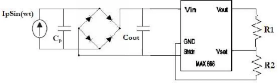
4.2 Power storage circuit with a voltage regulator MAX 666 . . . 33
4.3 PIC connections. The output of the first PIC is connected to the interrupt input of the second PIC. First PIC is powered by DC powr supply and the second PIC is connected to the output of MAX666. . . 35
4.4 The voltage generated on the output capacitor in the circuit drawn
in Figure 4.1 . . . 36
5.1 Circuit for measuring the resonance frequency of the bimroph. Taken from www.americanpiezo.com . . . 39
5.2 The voltage on the output resistor given in Figure 5.1. The point where the voltage is maximum(or resistance of the bimorph is minimum) gives the resonance frequency of the system. . . 40
5.3 Theoretical Power output versus input frequency. This graph is the solution of the system equations described in Chapter 3. . . . 42
5.4 Power versus Resistance for the phantom experiment. The points are the experimental results and the fitted curve is the theoretical output for the given displacement . . . 43
5.5 Voltage on R for a static input. . . 44
5.6 Time Decay of the system used to measure the capacitance of the bimorph . . . 45
5.7 A sample output of the phantom experiment for the 6cm long bimorph. . . 46
5.8 Spectrum of 6cm device without end-load . . . 47
5.9 Spectrum of 6cm device with 5.3 gram end-load . . . 47
5.10 Spectrum of the 2cm bimorph . . . 48
5.11 New Design . . . 48
5.12 Voltage waveform generated by the z-shaped design(with 3.1gram end-load) . . . 49
5.13 Spectrum of voltage generated by the z-shaped design(with 3.1gram end-load . . . 49 5.14 Voltage waveform generated by the z-shaped design(with no
end-load) . . . 50 5.15 Spectrum of voltage generated by the z-shaped design(with no
end-load . . . 50 5.16 The picture of the 6cm-bimorph and the z-shaped bimorph . . . . 51 5.17 Heart Phantom with z-shaped bimorph attached . . . 51
List of Tables
5.1 Change in resonance frequency with increasing tip mass . . . 41 5.2 Comparison of the Power Generator Prototypes . . . 46
Chapter 1
Introduction
A pacemaker is a small, battery-operated electronic device which is inserted under the skin to help the heart beat regularly and at an appropriate rate. A pacemaker system consists of a pulse generator (actual pacemaker) and either one (single chamber) or two leads (dual chamber) connected to it. The actual pacemaker has two main parts: batteries and electronic circuitry.
The electronic circuitry draws power from the batteries and transforms this power into appropriate electrical pulses. These pulses are carried to the heart by an insulated, flexible wire called the pacing lead. Some early pacemakers dis-charge electrical pulses at a fixed rate which are called asynchronous pacemakers but today almost all pacemakers work asynchronously on demand. Synchronous pacemakers senses the heartbeats and if the heart is beating normally at its own it does not send the pulses. Also today’s ”rate responsive” pacemakers mon-itor several parameters, including the blood temperature and respiratory rate, which reflect the level of physical activity and affect the demands on your heart. Changes in these parameters prompt the pacemaker to adjust the heart rate up or down, as needed. For example, they can increase the heart rate during exercise to meet the increased need for blood and oxygen.
1.1
Motivation
Magnetic resonance imaging (MRI) is considered to be the premier non-invasive imaging modality. It uses magnetic fields and radio waves to create high-quality cross-sectional images of the body without using radiation. There are now ap-proximately 15 000 MR systems worldwide, and 35 million MR studies performed yearly. Unfortunately, the policies of most radiologic institutions and professional organizations indicate that the presence of a cardiac pacemaker is a strict con-traindication for MRI [11]. A 1999 Japanese study found that 17 percent of patients with pacemakers were denied MRI in the previous year [40]. This study shows that there is a strong correlation between the patients implanted a pace-maker and patients that need an MRI scan. More than 900 000 pacepace-makers were implanted worldwide in 2003, and since 1999, implantation rates have increased 56 percent per year [8]. So this contraindication prevents MRI from being used in many patients that could benefit from this important diagnostic tool.
1.1.1
MRI safety of Pacemakers
The reasons of the contraindications of pacemakers for MRI can be grouped into 3 main areas:
1-Disfunctioning in the pacing signal because of the induced current on the pacing lead. This may results in as alterations of pacing rate, especially rapid pacing . In Hayes et al. [6], rates up to 300 beats/min have been observed in animal studies. In the extreme case this induced current may result in a fibrillation in the heart and may cause a patient death.
2-Damage in the cardiac tissue due to the temperature increase at the tip of the heart [9] [31] [32].
3-Or if a reverse current is induced in the pacing lead a damage to the pulse generator circuitry may be observed or it may disrupt the sensing signal coming from heart which may results in an arrhythmias.
Previous research made on designing an MRI compatible pacemaker showed that using fiber-optic cables instead of standart pacing leads solves the safety problem. But this approach is limited by the increased power consumption be-cause of the fiber-optic cables. Overall goal of this thesis is investigating the feasibility of a power generator that is placed near the heart which uses the mo-tion induced by heart in order to supply the necessary power to the pacemaker. In the next section, a literature review of vibration-to-electric converters will be presented.
1.2
Literature Review
Power generation using environment vibrations has lots of application such as automobiles, motors, factories and human body. Although there are groups worked on this subject it can still be considered as an open subject.
1.2.1
Literature Review on MicroPower Generators
One of the early work on vibration to electric generators was done by Yates, Williams, and Shearwood [5][4], an electromagnetic micro-generator. In their work, they have modeled the power generator as a second order mass-spring-damper system and stated that the generated power can be considered as a second linear damper to the system. The size of their power generator was 4mm x 4mm x 1mm and produced below 1 µW for a displacement of 500nm at 70Hz. They also tested and simulated their design with higher frequencies in the range of Khz and stated that as long as the displacement is taken as constant the
generated power increases with the cube of increasing frequency. Main drawback of the design is the voltage level produced by the generator which is in the mVs region and the level of the vibrations they used. Since the generator produces an AC voltage a rectifier is needed and in order to achieve a reasonable rectifying a transformer with a very large gain factor should be used which makes this design not applicable. Also the vibrations they used at higher frequencies are not practical since their displacement values are too high for real life vibration sources.
Another electromagnetic generator was developed by Amirtharajah et al. [28] [26]. The electromagnetic converter was designed for vibrations with a displace-ment of 2cm at 2Hz. The size of the device was 4cm x 4cm x 4cm. Their main goal was converting the vibrations created by a walking person by placing this device on the clothes of the person. Like the design made by Williams et al.[5], the main drawback is the low output voltage generated which is reported to be 180mV. Since their target input frequency is small 2cm displacement is achievable in human walking.
Same group also designed an electrostatic converter which was designed for vibrations at 2.52 KHz. The size of the device is 1.5 cm X 0.5 cm X 1 mm. They stated that it is possible to extract around 10 microwatts from this device but no experimental results were presented. Also like Williams et al., their design is matched for a high frequency and they did not report the amplitude of the vibrations they used or they targeted for this design. They also designed a digital signal processing sensor to be used with the design. The design minimizes the power consumption by using the sleep mode of the microprocessors when it is not working.
An important paper on the limits of power generation from human motion is written by Starner et al. [35] in 1996. He performed certain experiments and calculations to find out the available power from different human activities. He
investigated main body motions like walking, breathing and arm movement, and also sources that exist without any motion like body heat and cardiovascular motion. He calculates that approximately 67 W of power is lost during walking and that a piezoelectric device mounted inside a shoe with a conversion efficiency of 12.5 percent could achieve 8.4 W of power. It is suggested to place piezofilm patches in the joints of clothing to harvest the energy lost during bending and he states that about 0.33 W could be obtained. One important conclusion for the paper is that the energy generated will never be constant and energy may not be produced at all, making the use of a power storage medium a must. Power should be stored when it is available so that the device that will be powered can work without any disfunction. He also states that energy storage in a capacitor would be sufficient for low-power areas such as blood pressure and body heat, but rechargeable batteries are a must for higher power areas, such as limb motion and walking.
There are also some groups worked on piezoelectric generators that are placed under the shoe of a person and generates power at each step. Kymissis et al. [22] reported to generate a maximum of 80 milliwatts from their device. They used this energy to power a radio-frequency circuit. They used a capacitor charging-discharging system. Although their work is quite different from this project since the input is force instead of vibrations for this case, their power generation circuitry and RF circuit can be used for many applications including piezoelectric converters.
1.2.2
Literature Review on Piezoelectric Power
Genera-tors
Interestingly, the first idea of using piezoelectric power generators using the vi-brations of human body was for a self-powered pacemaker. W.H. Ko had a patent
[38] about a cylinder piezoelectric power generator which uses the vibrations of the heart to produce the necessary energy to power the pacemaker. No theoreti-cal or experimental results are reported about this work. The main drawback of the system is the fragility of the piezoelectric materials. So probably this work has no practical use in real life although it is the first reported research about the subject.
The first experimental work about power generation using the vibrations of the human body is published by Hausler and Stein in 1984 [7]. They used polyvinylidene fluoride (PVDF) films to extract power from the relative motion of the ribs which is induced by respiration. The generated power was too low since the frequency of the breathing is too low to produce reasonable motion.
In 1996 Umeda et al., experimented a power generator consisting of a piezo-electric stack and a steel ball [24] [25]. They investigated the power generation characteristics of a piezoelectric generator by dropping the steel ball from a cer-tain height. Although this work is not related with this project since it mainly focuses on the impulse response rather than a periodic motion, it is quite impor-tant since it is one of the first papers investigating the power generation models for piezoelectric generators.
Goldfarb and Jones [23] have analyzed the power conversion efficiency of a piezoelectric stack which has a natural frequency at 40KHz. They found out that at high frequencies the piezoelectric material stores a big portion of the energy produced and returns it to the excitation source. So if the efficiency is defined as the ratio of the electrical power recovered from the piezoelectric material to the input power the efficiency is much smaller for higher frequencies especially in the KHz range. They also showed that maximum efficiency occurs below 100Hz for their design. They state that the reason behind this behaviour occurs when the piezoceramic is placed in parallel with a capacitor that is in series with the load.
When the frequency is high the input capacitance of the piezoelectric material is charged instead of the load capacitor.
Elvin et al. (2001) [27] tried to power a telemetry circuit using a used PVDF attached to a plexiglass beam. The energy generated was used to charge a capacitor which powers the telemetry circuit. A switch was added to the circuitry to allow the capacitor to charge to a value of 1.1 V. At that point the switch is closed and the telemetry system transmits. When the voltage on the capacitance is below 0.8 V the switch opens and disconnects the telemetry system from the generator. They succeed in transmiting a signal containing information regarding the strain of the beam a distance of 2 m.
In 2004 Roundy et al. [30][29] published two papers on vibration-to electric power generation. In the first one they designed two electrostatic power generator using capacitor charge-discharge principle and a piezoelectric power generator which uses PZT bimorphs. They showed that the overall output power of the piezoelectric power generator is higher than the electrostatic power generator and also it does not need an additional power supply. Their PZT device was capable of producing 250W/cm3. One important results from their work is although the output power seems to be directly related with vibration frequency, in reality it is nearly impossible to find same level vibrations at higher frequencies. So they defined the magnitude of the vibrations as the acceleration of the vibrations and showed that actually if a power generator can be designed for a lower frequency at the same acceleration level it will produce more power than its high frequency matched counterpart.
In their next paper they tried to optimize the design of a piezoelectric power generator using the Mason’s equivalent circuit model for a piezoelectric element and the known equations of second order vibrations with a spring and damping. They simulated their generator with a resistive load and a capacitive load and found the output power equations. Then they optimized the power output with
respect to the load impedance for both designs. They also verified the simulations with an experiment using a vibration of 2.5m/s2 acceleration at 120Hz. They produced 375W/cm3 from their device. At the discussions part they advised that the generator should be designed to resonate at the dominant driving frequency and if two frequencies has comparable acceleration values the one at the lower frequency should be selected to maximize the output power.
Platt et al. [33] made a research on powering orthopedic knee implants using a piezoelectric stack. They have produced 4.8mWs from a 1.2cm3 device with a 440N force. But a more important results that they reported was on the longetivity of the piezoelectric stack. They have tested their device for 6 million cycles and only a 4.4 percent decrease of the electrical power is reported. They have also made a calculation that even for 108 cycles the maximum degradation
that can happen is below 17.8 percent.
1.2.3
Literature Review on Power Storage Circuitry
Ottman et al. [13] and [14] published two papers in 2002 and 2003. The main goal of these papers have been optimizing the power conditioning electronics for the storage of the energy produced by the piezoelectric power generators instead of improving the design of the generator. They showed that by using an active circuit with opamps and inductors the power output of a piezoelectric generator can be significantly increased. Of course in order to this approach be effective the power output should be above a certain lever to power the additional circuitry. They experimented their design with a piezoelectric device of an area 19cm2 and improved the power output from 4.6mW to 18mW.
One other group who worked on power circuitry design published their work in 2004 [17]. Again they do not attempt to optimize the piezoelectric power generator design but instead they tried to minimize the power output of a certain
piezoelectric generator. They used a stack of piezoelectric membranes as the power converter and implemented synchronous and asynchronous rectifier circuits to the output of the piezoelectric. In their simulations they represented the output from the power generator using the FFT (Fast Fourier Transform) of an actual PZT output waveform and took the first seven harmonics of the FFT. They showed that the synchronous rectifier improves the efficiency of a diode-diode pair rectifier by more than double times. In their design instead of diode-diodes they used an opamp diode pair to ensure synchronous rectification so that the on-voltage of the system reduces to the on-on-voltage of a single diode. The drawback of this circuit is although the power consumption of the opamp are considered in the calculations nevertheless the circuit is active.
Sodano et al. [15] investigated the power storage circuits and compared two simple circuits, a rechargable battery system and a capacitance charging system. It is stated in the paper that although using rechargable battery is more practical and efficient approach, the current lifetime of rechargable batteries is a concern. He demonstrated that a single capacitor charging circuit with a full-wave rectifier can be used for power storage.
1.3
Organization of the Thesis
In the first chapter motivation behind this work was stated. Also background knowledge about pacemaker-MRI contraindication was given. Then related work on the vibration to electric power converters, which will form the main subject of this thesis, is given. In the next chapter the solution approach for solving the contraindication and the reasoning behind the need for an additional power gen-erator will be discussed. Also the required energy and design constraints will be stated. Chapter 3 starts with the main basic knowledge of Piezoelectricity and Piezoelectric Bimorphs. Then a general model for a vibration to electric power
converter will be derived. This model will be modified for a piezoelectric power generator and after that piezoelectric power generator design parameters and their equations will be derived or given using a reference. Chapter 4 starts with a discussion on selecting the circuit model for the piezoelectric bimorph. Then the power generation, rectification and storage circuitry will be introduced. After a simple pulse generator circuitry using a microprocessor is presented the chapter ends with the experimental results on this circuitry. In Chapter 5, the imple-mentation and material selection of a piezoelectric power generation is followed by the experimental results on the piezoelectric characteristics of the constructed power generators. After the results of a standard piezoelectric bimorph is tabu-lated a new design approach for improving the power output in a given region is presented and its test results are given. The thesis ends with Chapter 6, where the results are discussed and concluding remarks are given.
Chapter 2
System Definition
2.1
Problem Definition
It was shown in [9] that the part of the pacemaker that is responsible for the contraindication with MRI is the lead of the pacemaker. Although with elec-tromagnetic filtering techniques, the case of the pacemaker can be made MRI compatible; no pacemaker lead design which can totally prevent the induced current and the temperature increase at the tip of the lead has been produced.
2.2
Fiber-optic Cables
In Shellock et. al [11] and [12], it was shown that changing standart pacemaker leads with fiber-optic cables can solve the MRI compatibility problem. They also produced (Biophan) an external Temporary Pacemaker which is connected to the heart with fiber-optic cables and tested the system in a 1.5-Tesla MR system. The results show that fiber-optic cables are MR compatible in terms of:
- Magnetic Field Interaction: The maximum deflection angle of the fiber-optic leads is measured to be 23 degrees which is smaller than the maximum allowed deflection angle defined by the ASTM criteria. This shows that the pacing signal can be transmitted through the fiber-optic leads without being affected from the MR field.
- Heating: Also as shown in Shellock et. al [11],[12] the maximum temperature increase at the tip of the fiber-optic leads is measured to be 0.8degrees. This experiment is done using a 1.5 Tesla MR system and with an specific absorbtion rate(SAR) of 1.5 W/kg. This temperature increase is below the standarts defined by the FDA. So we can conclude that MRI-related heating for the fiber-optic lead of the a pacemaker will not present any additional risk to a patient undergoing an MRI procedure under the conditions used for this evaluation.
- Biocompatibility: Fiber-optic cables are also biocompatible. They have been used in previous studies in human body and no report has been published about its non-biocompatibility.
2.2.1
Disadvantages of Using Fiber-optic Cables
Although a temporary external pacemaker with fiber-optic leads has been pro-duced no internal pacemakers has been propro-duced. The main reason behind this is the additional power requirement of the fiber-optic data transmission. The power consumption of the pacemaker increases because of:
1- Power loss on the fiber optic cables. The maximum efficiency which can be achieved for pacemaker case is approximately 20 percent. So the lifetime of the pacemaker will reduce to 1-2 years which is not feasible.
2- Also an additional mechanism is needed to convert the optic signal coming from the pacemaker case to electrical signal so that the heart can be paced. This
brings additional power consumption and also a battery will be needed at the tip of the pacing lead for powering the conversion circuitry.
2.3
Solution Approach
In this thesis it is proposed that a power generator placed at the tip of the pacing leads can use the motion of the heart as an input and can convert this energy into necessary electrical power to pace the heart. In the following sections of this chapter first the overall system will be defined and then the design constraints for the power generator circuitry will be determined and finally possible methods for vibration to electric power conversion will be compared.
2.4
Overall System
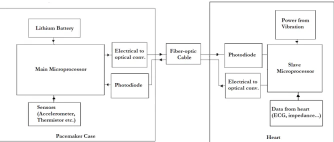
The overall system is described in Figure 2.1. The first microprocessor will be responsible for the determination of the pulse characteristics for pacing the heart. It will be placed into the case of a pacemaker and will be powered by a lithium battery. The output of the pacemaker will be transformed to a optical pulse using a electrical to optical converter. The pulse will be carried via fiber-optic cable to the second module placed in the heart. This module will consists of a power generator and a second microprocessor which will be used as a pulse generator. The optical signal will be detected by a photodiode and will be send to the interrupt input of the microprocessor to awake the microprocessor. After that the microprocessor will process the input signal and produce a simple square wave pulse according to the given code and pace the heart.
Figure 2.1: System Block Diagram
2.5
Energy needed for the pacing signal
There are different types of pacemakers so the energy dissipation of a pacemaker is reported differently in different sources:
Constant-voltage or constant-current amplitude pulses are the two usual types of stimuli produced by the output circuit. Constant-voltage amplitude pulses are typically in the range of 5.0 to 5.5 V with a duration of 500 to 600 µs. Constant current amplitude pulses are typically in the range of 8 to 10 mA with pulse durations ranging from 1ms to 1.2ms. Rates for synchronous pacemakers range from 60 to 150 beats per minute. (70beats per minute average) [20].
Modern pacemakers use constant voltage pulses. Average energy per pulse can be taken as 25J [20].
Stimulation of heart needs 16 to 20 J per pulse [21].
If energy per pulse is taken as 25 J and heart rate is taken as 70 beats per minute, average power consumption is about 30 W. With an average current drain of 30W, a 2 A-h battery would last more than 10 years [19].
N = 70 min-1 x 60 min/h x 24 h/d x 365.25 d/yr x 10 yr = 3.68 x 10⁸ pulses Et =3.68 x 10⁸ pulses x 25 J = 9.2kJ
Battery capacity = 9.2kJ/5V = 1.84A.ks = 0.51 Ah. (units Ampere hour) This is the total capacity we need ( Pulses take approximately 25 percent of all power consumption in a standard pacemaker so they need 2A.h ). So in conclusion we need approximately 30 W energy for pulses. But these values are for pacemakers that are build in 1990s.
Additional information provided by Medtronics:
Recently build pacemakers can give pulse amplitude in the range 0.5 to 6.5 V ( 0.5 V increments) and pulse width 0.1 to 1.2 ms (in 0.1 ms increments) [2]. Optimal threshold values for the pulse amplitude and width is given by 3.5 V amplitude and 0.4 ms pulse width for ventricular stimulation. Considering the resistance of heart is around 500 ohm this pulse corresponds to approximately 10µwatts.
2.6
Design Constraints
So approximately 15-30uW is needed to pace the heart. But a pacemaker should be able to adjust its pacing rate according to the information which is acquired from the heart and the human body. Among these, acquiring electrocardiogram (ECG) signal is the most important one which should be acquired directly from the heart. So a circuit which can take and process this signal is mandatory.
A Programmable Integrated Circuit(PIC) can be used for this purpose. But since a standart PIC is design for multiple purposes it consumes more power than needed. So we used an algorithm such that when there is no pacing signal coming from the main pacemaker, the PIC is in the sleep mode where it consumes 1uW.
It wakes up when a trigger signal from the main pacemaker is sent and then give a pulse according to the information sent by the main pacemaker. So the idea is using the PIC as a dump pulse generator when no other function is needed. By this way the power consumption can be reduced to:
Another power consuming device will be the photodetector which will trans-late the optic signal coming from the fiber-optic cables to an electrical signal so that the PIC can communicate with the main pacemaker.
So it is safe to say that the overall design needs power around 50 microwatts to function properly. Considering that the dimensions of the power generator should be at most 3cm × 4mm × 4mm, a power generator with a power density of 100microwatts/cm3. Considering the vibrations of the heart the target input vibrations should be taken to be peaked around 1Hz.
Chapter 3
Piezoelectric Power Generation
3.1
Introduction to Piezoelectricity
Piezoelectricity is a phenomena that some materials do possess. When a piezo-electric element is stressed mechanically by a force, it generates an piezo-electric charge ( Direct Piezoelectricity ). The effect is reversible; piezoelectric materials, sub-ject to an externally applied voltage, can change shape by a small amount ( Converse piezoelectricity ). In a non-excited piezoelectric crystal, the positive and negative electrical charges are separated, but symmetrically distributed, so that the crystal overall is electrically neutral. When a stress is applied, this sym-metry is disturbed, and a non-zero charge occurs on the material. Due to these characteristics they have been used in numerous applications such as sensors, actuators, buzzers and ultrasonic transducers.
3.1.1
History of Piezolectricity
Piezoelectricity was found in 1880 by the brothers Pierre Curie and Jacques Curie. They showed that crystals of tourmaline, quartz, topaz, cane sugar, and
Rochelle salt generate electrical polarization from mechanical stress. Converse piezoelectricity was mathematically deduced from fundamental thermodynamic principles by Lippmann in 1881. The Curies immediately confirmed the existence of the ”converse effect,” and went on to obtain quantitative proof of the complete reversibility of electro-elasto-mechanical deformations in piezoelectric crystals. The first practical application for piezoelectric devices was sonar, first developed during World War I. In France in 1917, Paul Langevin developed an ultrasonic submarine detector. The detector consisted of a transducer, made of thin quartz crystals carefully glued between two steel plates, and a hydrophone to detect the returned echo. By emitting a high-frequency chirp from the transducer, and measuring the amount of time it takes to hear an echo from the sound waves bouncing off an object, one can calculate the distance to that object [34].
3.2
Piezoelectric Parameters and Relationships
The electrical behaviour of an unstressed medium can be defined by two quanti-ties: field strength E and the dielectric displacement D which are related by:
D = ²E (3.1)
where ² is the permittivity of the medium.
Likewise the mechanical behaviour of a medium at zero electric field strength can be defined by two quantities: the stress applied T and the strain S which are related by the:
S = sT (3.2)
where s is the elastic compliance of the medium.
Piezoelectricity involves the interaction between the electrical and mechanical behaviour of the medium. To a good approximation this interaction can be
S = sET + dE (3.3)
D = dT + ²TE (3.4)
Here the superscripts to the symbols denote the quantity kept constant under boundary conditions. For example if the applied stress T is kept constant super-script T is used. So sE is the elastic compliance for a constant electric field and
²T is the permittivity at constant stress.
The piezoelectric charge constant, d, is the polarization generated per unit of mechanical stress (T) applied to a piezoelectric material or, alternatively, is the mechanical strain (S) experienced by a piezoelectric material per unit of electric field applied.[3]
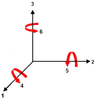
Figure 3.1: Notation of axis
Because a piezoelectric ceramic is anisotropic, physical constants relate to both the direction of the applied mechanical or electric force and the directions perpendicular to the applied force. Consequently, each constant generally has two subscripts that indicate the directions of the two related quantities. The direction of positive polarization usually is made to coincide with the Z-axis of a rectangular system of X, Y, and Z axes. Direction X, Y, or Z is represented
by the subscript 1, 2, or 3, respectively, and shear about one of these axes is represented by the subscript 4, 5, or 6, respectively.
For example, d31 represents the induced polarization in direction 3 (parallel
to direction in which ceramic element is polarized) per unit stress applied in direction 1 (perpendicular to direction in which ceramic element is polarized).
Another parameter is the piezoelectric coupling coefficient k, which is a mea-sure of electromechanical effect. For the direct piezoelectricity case it is defined as the square root of the total mechanical energy input divided by the electrical energy output.(Eq.3.5) Although a high value of k is desirable for efficient energy transform k2 should not be considered as a measure of efficiency since dissipative
mechanisms are not taken into account when calculating k.
k =
s
stored electrical energy
supplied mechanical energy (3.5)
3.3
Piezoelectric Bimorphs
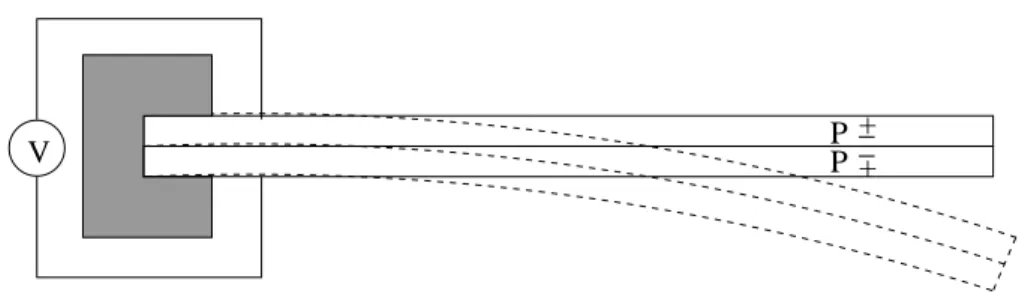
A piezoelectric bimorph is a device that consists of two piezoelectric layers joined over their long surfaces,provided with electrodes such that when one layer elon-gates the other layer contracts. A charge is developed across the bimorph in order to counteract the imposed strains. Usually a metal shim is placed be-tween two piezoelectric layers which provides mechanical strength and stiffness while shunting a small portion of force. There are two possible orientations for bimorphs; a series operation and a parallel operation.
A bimorph operated as a series operation consists of two layers that are reversely polarized and the voltage difference is taken from the two electrodes that are placed at the outside the two layers. (Figure 3.2)
P P
V + __
+
Figure 3.2: Bimorph operated in series mode
A bimorph operated as a parallel operation consists of two layers that are polarized at the same direction but the voltage difference is taken from the three electrodes such that one electrode which can be labelled as positive is placed between the piezoelectric layers and the other two electrodes are placed at the outside of the two layers.(Figure 3.3)
Figure 3.3: Bimorph operated in parallel mode
Series and parallel bimorphs are energy equivalent. As a voltage generator series type has the twice open circuit sensitivity then parallel type. But when used as an actuator parallel type has twice the ratio of deflection per applied voltage. So generally series types are used as sensors and parallel types are used as actuators.
In this project a bimorph is used because of the following advantages: -It provides a smaller resonance frequency which is important since our target frequency range is very small compared to the resonance frequency of other
and they are used in the 31 mode. Since stiffness is low, resonant frequencies can be low.
-It has a higher piezoelectric voltage coefficient so for a given input strain it generates more voltage which will increase the generated power.
- Bimorphs have enough mechanical strength in the high vibration conditions of frequency 110 Hz. In this limit the applied load on the bimorph can be of the order of few newtons. Laboratory scale measurements made by Priya et al. have shown that a bimorph vibrating under a force of 2N at low frequencies of 10 Hz do not suffer from any mechanical degradation.
Bimorph (or a two-layer bending element) is mounted as a cantilever beam as shown in Figure 3.2 is used. The polarization is along the z-axis (3 axis) and also the structure will vibrate in the z-axis direction. So the bimorph will experience along the x-axis(1 axis). So the bimorph is used in the 31 mode. So the equations 3.3 and 3.4 can be written as:
S1 = sE11T1+ d31E3 (3.6)
D3 = d31T1+ ²T3E3 (3.7)
A mass is put at the tip of the cantilever beam. The main reason to use a mass is to adjust the resonance frequency of the bimorph. In Goli et al. [16] it was shown that when the reduced mass which can be defined as the tip mass normalized to the mass of the cantilever beam is increased beyond 1, the resonance frequency of the system decreases. Also in Roundy et al. [30], it was shown that generated power is proportional to the tip mass.
3.4
General Vibration Model
The differential equation describing the general model for a vibration-to-electric converters can be found by equating the dynamic forces on the vibrating body. [39] With the assumption of a simple mass-spring-damper system the differential equation of motion can be written as:
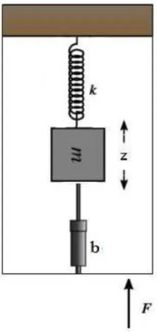
Figure 3.4: Model of the system
m¨z + b ˙z + kz = F = m¨y (3.8) Where: z is the spring deflation, y is the input displacement, m is the mass of the system, b is the damping coefficient, k is the spring constant and F represents the force applied.
Since the main goal is converting the mechanical energy to electrical power, a term describing the energy taken from the system should be added to this equation. An assumption can be made to define this energy removal as a second linear damper to the mass spring system. So the equation becomes:
m¨z + (be+ bm) ˙z + kz = F = m¨y (3.9)
where: be is the electrically induced damping coefficient and bm is the
mechani-cally induced damping coefficient
For further cancellation these two variables can be replaced by:
be = 2mξewn (3.10)
bm = 2mξmwn (3.11)
consequently where ξ is the damping ratio and wn is the natural frequency of the
system. Resonance frequency is given by:
wn=
r
k
m (3.12)
The system can be solved by taking the fourier transform of both sides of equa-tion 3.9, using equaequa-tion 3.12 and finding the relaequa-tionship between the fourier transform of input displacement and spring deflection which is given by:
Z(w) = −w
2
−w2+ 2jww
n(ξe+ ξm) + w2n
Y (w) (3.13) where w is the frequency of driving vibrations.
The electrically produced power can be calculated as the electrically induced force times the velocity which is given by [5]:
|P | = 1
2be˙z
2 (3.14)
taking the derivative of equation 3.13 and placing into Eq. 3.14 the relationship between the input displacements and the generated power can be acquired as:
|P | = mξewnw 2Y2(w wn 3) 4((ξe+ ξm)wwn)2+ (1 − wwn2)2 (3.15) Which is actually the same equation found by Williams et all.[5]
If it is assumed that the input vibrations match the natural frequency of the system such that w=wn the equation can further be reduced to:
|P | = mξew 3Y2 4(ξe+ ξm)2 = mξeA 2 4w(ξe+ ξm)2 (3.16) In their paper they concluded that the maximum power that can be achieved from a certain design is proportional to the cube of the input vibrations. This statement is valid if it is assumed that the displacement of motion is constant with increasing frequency. But in 2000 Roundy et all [30] showed that this assumption is not logical practically. They made a research about the possible vibration sources and showed that with increasing frequency the displacement of the vibrations decrease drastically. So instead of comparing two vibrations with respect to their displacement a better approach is comparing their accelerations. This is also a better approach in terms of efficiency considerations since by taking the acceleration constant we assure that two systems face same input vibrations. So assuming a sinusoidal input vibrations with constant acceleration the equa-tion becomes: |P | = mξew 3Y2 4(ξe+ ξm)2 = mξeA 2 4w(ξe+ ξm)2 (3.17) It should be noted that here the frequency w corresponds to both the natural frequency of the system and the input vibrations. So this equation states that if possible the converter should be designed to match the lowest peak in the spectrum of the target vibrations.
3.5
Piezoelectric Power Generation Model
In the previous section the model for a power generator was derived with the assumption that the energy removal can be modelled as a linear damper in the system. However, this may not be a good approximation for the piezoelectric bimorph case. Instead in this section we will use ”charge” as the energy removed from the system. The circuit model given in Figure 3.5 will be used.
Figure 3.5: Circuit Model for Piezoelectric Power Generator. Taken from Roundy et all [30]
With this assumption the equation Eq 3.9 will be changed to [15]:
m¨z + b ˙z + kz − kmqCp−1 = F = m¨y (3.18)
where km is the electromechanical coupling coefficient of the piezoelectric
mate-rial that is used which relates the applied force on the piezoelectric matemate-rial to the voltage induced between the top and bottom layer of the piezoelectric sheet. Since a piezoelectric bimorph is used in this work km31 is used as the
electrome-chanical coupling coefficient. Considering the circuit model given in Figure 3.5 we can equate the charges at node a as:
kmz = V Cp+ q (3.19)
R ˙q − kmzCp−1+ Cp−1q = 0 (3.20)
Equation Eq 3.18 and Eq 3.20 form our coupled system equations, which can be solved for the output charge in terms of the input vibrations. We solved these equations by assuming a sinusoidal input displacement of Ysin(wt) and a charge output of Qosin(wt+θ). The maximum power can be calculated as the power
dissipated on the load resistance R:
|P | = km2Y2w2R
2(1 + w2R2C2 p)
(3.21) after taking the derivative of this equation with respect to R the optimum R can be calculated as [30]:
R = 1 wCp
(3.22) As discussed in section 3.3 the input vibrations will be modelled as a sinusoidal waveform with a constant acceleration with changing frequency. Since accelera-tion is the second derivative of displacement a sinusoidal input with a frequency w and with an amplitude a/w2 is applied.
3.6
Natural Frequency Calculations and Effect
of the Additional Tip Mass
The dynamic characteristics of piezoelectric bimorph mounted as a cantilever beam is well known and studied. In 1994 Smits and Ballato [18] calculated the dynamic admittance matrix of a piezoelectric cantilever beam and by solving those equations the natural frequency of the cantilever beam can be found as:
w = 1.85 2 L2 s EI ρA (3.23)
where: E is the Young Modulus of the piezoelectric material used, I is the Moment of Inertia of the Beam, ρ is the density of the piezoelectric material, A is the cross-sectional area and 1.85 is the normalized frequency corresponding to first resonance
In a future work citing this paper Goli et all studied the effect of tip mass on the resonance frequency of the cantilever beam. [16]. They obtained a graph of the first resonance frequency versus the normalized mass. Here normalized mass can be described as the equation below:
normalizedmass = madd mp
(3.24) where madd is the additional mass and mp is the mass of the beam given by:
mp = 2ρptpwplp+ ρshtshwshlsh (3.25)
where w, t and l the width, thickness and length and subscript p indicates piezo and subscript sh indicates metal shim.
They showed that when the reduced mass is below 0.01, the resonance fre-quency is nearly constant. After this value the resonance frefre-quency decreases linearly with increasing reduced mass. After a certain point the graph reaches a point where the cantilever can not withstand further mass increase. The calcu-lations of the resonance frequency for this structure are beyond the scope of this text, therefore they will be omitted. Instead the graph that Goli et all calculated will be used as a further reference as given in Figure 3.6.
An important fundamental limit on the maximum power that can be ex-tracted from the piezoelectric beam is the maximum force that can be applied
Figure 3.6: Normalized Resonance Frequency versus reduced mass. Taken from Goli et all [16]
to the beam which is given by the multiplication of the weight of the tip mass and the acceleration of the motion that the beam experiences.
Maximum strain generated in the piezoelectric material for a given force can be calculated as [39]:
σmax =
6F L
wt2 (3.26)
Where: F is the applied force in Newtons
L,w and t are the dimensions of the beam: length, width and thickness This equation can be modified for a piezoelectric bimorph as:
mmax =
σmaxw(tsh+ 2tp)2
6(g + a)lp
Chapter 4
Circuits
4.1
Modelling Piezoelectric Bimorph
The mechanical part of the piezoelectric bimorph which is represented as a mass-spring-damper system as shown in figure 3.4 can be transformed to a electro-mechanical lumped element model. For example the internal electro-mechanical losses in the system can be represented as a single lumped damping element. Construct-ing a one-to-one analogy between a mechanical system and an electrical system these losses can be represented as a resistor in the electrical model. Likewise the mass of the system can be considered as a single lumped mass element which can be represented as an inductor in the electrical lumped element model. The stiffness term which represents the piezoelectric coupling between the electrical and mechanical systems can be modelled as a capacitor in the electrical model. This model as shown in Figure 3.5 in the previous chapter can be solved for an input vibration. But here when considering the energy harvesting circuit the mechanical side will be assumed to be a sinusoidal current source. The reason-ing behind this assumption is the fact that for a sinusoidal input vibration the
piezoelectric bimorph produces a sinusoidal current. So the important modelling for this chapter is the modelling of the electrical side of the bimorph.
Considering the voltage and charge relations in the piezoelectric materials in the low frequency region the piezoelectric bimorph can be modelled as a capaci-tive source.
So from this point the piezoelectric material will be modelled as a sinusoidal current source with a capacitance connected parallel to it. In some sources these devices are modelled as a resistor and capacitor both connected series to a sinusoidal voltage source. The resistor value is very small compared to the impedance of the capacitor under 1Hz and therefore it will be neglected. So for our case these two models are approximately constant. This model will be validated in the next chapter.
4.2
Power Generation and Storage Circuitry
Since the input vibrations that the piezoelectric bimorph experiences are assumed to be sinusoidal, the output electrical power is in the form of alternating current. Considering that the electronic circuitry that is needed to pace the heart will need a direct current input the generated power must be rectified in order to be effective. Fortunately unlike other power generation techniques like electrostatic and electromagnetic power conversion, the voltage output of the piezoelectric bimorph is quite large. Therefore in most other cases a transformator with a gain around 10-100 is needed where as in piezoelectric power generation case the output can be rectified directly.
Here a simple full-wave rectifier circuit will be used in order to rectify the AC voltage. In some of the references [17] a half-wave rectifier or a voltage doubler circuit is proposed. But in these cases the input is a constant force instead of
a sinusoidal vibration and therefore the output current is mostly positive. An interesting full-wave rectifier was proposed by Han et al. [17]. Their idea called ”synchronous rectifier” uses a MOSFET and a low power opamp instead of the second diode in the full-wave rectifier. Although this circuit works well it is not used in this work since it includes an OPAMP which is an active element. In their work they power the OPAMP with an external power supply but in our case this is not possible.
So in all simulations and experiments a standart full-wave rectifier is used. The diodes are selected as Schotky diodes (Model 1N5819) since they have low on voltage values around 0.5volts. This decreases the main drawback of the full-wave rectifier which is the loss of the power input for values below two times the on voltage of the diodes.
In the experiments for measuring the properties of the piezoelectric bimorphs a single resistor or a potentiometer was connected to the bimorph directly. For the raw power calculations a full-wave rectifier was connected between the resistor and bimorph.
In order to power a microprocessor generated power needs to be stored. Power storage is also important in the cases where a malfunctioning occurs. For example the patients heart beat maybe delayed or it may stop for a few seconds. Although the pacemaker can not deliver the necessary high power pulse to the heart like ICD, it should still continue to pace the heart once the problem is solved. Power can be stored in two ways: A rechargable lithium battery can be used or a capac-itor charging-discharging circuitry may be implemented. Recharging a lithium battery has many advantages like constant voltage output and higher power stor-age density. Since the input vibrations are not constant recharging a battery is much easier than recharging a capacitor. But recharging batteries has a shelf life in terms of recharging cycle. So the life time of the battery is a crucial factor in
this process. No rechargable batteries that can last more than a year in a pro-cess that recharging-discharging occurs in a second is found and unknown to the author. Although a charging a lithium battery is with a piezoelectric bimorph is tested this method is not used in powering the pulse generator circuitry.
Figure 4.1: Simple power storage circuit
The capacitance value of the piezoelectric bimorph was measured to be 16nF. 1 micro farad, a relatively high output capacitor value was selected for better power transfer and storage.
The main problem with capacitor charging circuit is the output voltage level of the system. Since in our system there is no guarantee about the level of vibrations and therefore the level of output power, a capacitor charging circuit can not maintain a certain voltage output. Considering this device will be used to power a microprocessor a voltage regulator was added to the system. A low power voltage regulator MAX666 bought from Maxim Electronics was used for this purpose.
In some of the previous work, putting an inductor to the output of piezo-electric bimorph was reported to give improved results. The main advantage of this approach is the inductor matches the input impedance of the bimorph and therefore more power can be extracted from the bimorph. The main problem with this approach is the input frequency of the system and the available space. Considering our operating frequency is much lower than the given examples the value of the inductance that should be used is too high. Also taking into account the available space this method is not feasible for our system.
4.3
Pulse Generator Circuitry
As explained in Chapter 2, a simple electronic circuitry consisting of two micro-processors will be used as the pulse generator. The first microprocessor models the main microprocessor that will be put into the pacemaker case and the second microprocessor will be used as the pulse generator. The first microprocessor will be responsible for all the operations that a normal pacemaker does except it will only send an interrupt and a small data packet to the second microprocessor. Here for simplicity, the first microprocessor is used as a periodic pulse generator that send a 1 microsecond pulse with a frequency of 1Hz.
The second microprocessor was programmed as a asynchronous pulse gener-ator which generates a 1ms pulse after waking up because of the interrupt from the first microprocessor. After 1 miliseconds it automatically goes to the sleep mode and stays there until a new interrupt arrives. A normal microprocessor need around miliwatts in order to function properly. This power was reduced by using a low frequency crystal at 40 Khz instead of the suggested 4Mhz crystal. Since the microprocessor automatically divides this frequency by four, the clock time of the microprocessor is increased to 0.1msec. With this change the sleep
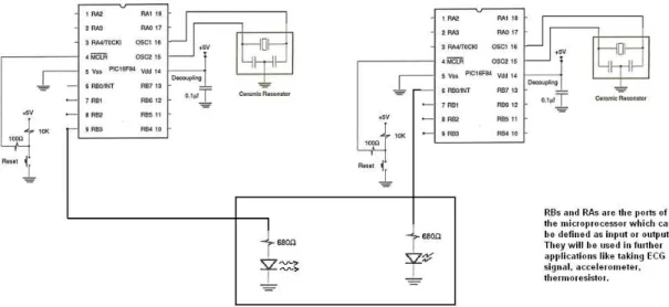
Figure 4.3: PIC connections. The output of the first PIC is connected to the interrupt input of the second PIC. First PIC is powered by DC powr supply and the second PIC is connected to the output of MAX666.
current was reduced below 5 µWs, which reduces the necessary power needed for functioning the microprocessor below 10 µWs.
4.4
Experimental Results
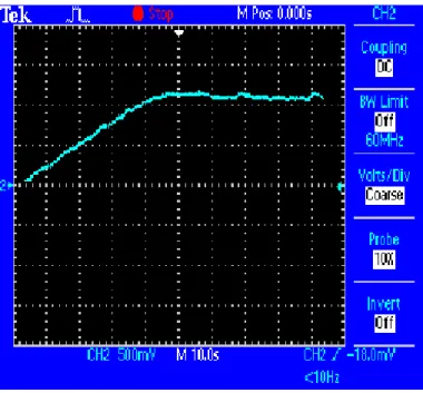
First the circuit in Figure 4.1 was experimented without a load resistor. The output of this circuit with the 6cm long bimorph as an input is shown in Figure 4.4. A 3.1gram end load was attached at the tip of the cantilever.
The capacitor is charged with the rectified voltage at the output of the full-wave rectifier. At around 1.2Volts the voltage on the capacitor becomes nearly constant. The value of the capacitor for this circuit was selected to be 10micro-farads. So the output power for this case can be calculated as 7.2microwatts.
Since the generated power was not enough to power the PIC, the overall circuit was tested by overdriving the 6cm long piezoelectric bimorph with extreme loading conditions. 3 Volts was generated on the 10 µF output capacitor and this
Figure 4.4: The voltage generated on the output capacitor in the circuit drawn in Figure 4.1
voltage is feeded to the PIC via MAX666 voltage regulator. The PIC successfully delivered 2 Volt 1msec pulses to an output resistance with 1 second intervals.
Chapter 5
Experimental Results
5.1
Implementation
of
Piezoelectric
Power
Generator
In order to verify the models developed in the previous chapter Three differ-ent piezoelectric bimorphs with differdiffer-ent dimensions are constructed. The first piezoelectric bimorph has dimensions of 6cm × 0.3cm × 0.051cm. The second bimorph had dimensions of 3cm × 0.3cm × 0.051cm and the last one is 3cm × 0.3cm × 0.0255cm. Then these bimorphs tested with a simple heart phantom which uses water, pipes and ballons to imitate simple heart motion.
5.2
Material Selection
Probably the most important decision for constructing the piezoelectric bimorphs is the type of the piezoelectric material used. Considering the equations derived in the previous chapter a high electromechanical factor is crucial in high power
efficiency. Considering the other facts as commercially availability, strain coef-ficient, price and longetivity Lead Zirconate Titanate(PZT) is selected. PZT is probably the most used piezoceramic in power generation designs. Specifically PZT-5H from (Piezo Systems Inc., 1998) is selected because of its good piezo-electric properties. The only drawback of PZT-5H is that it is more brittle than other commercially available piezoceramics.
Although PZT-5H has a higher electromechanical constraint in 33 mode, be-cause the resonance frequency is lower in 31 mode and more stress can be gen-erated in this mode, 31 mode is selected.
Since PZT-5H is a brittle material a metal shim is placed between the two oppositely polarized piezoelectric sheets to improve the maximum stress that the material can withstand and to prevent unwanted cracks. Aluminum is selected as the metal shim because of its high stiffness and its non-magnetic property. The two piezoelectric layers and the metal shim are attached together using a metal epoxy with high strength. As stated in Wu et all [36] the quality and the thickness of the bonding layer effects the resonance properties of the piezoelectric bimorph. A base for the piezoelectric was built using aluminum sheets. Then the bimorph was glued to the base to ensure stability. Also different weights of tip mass was attached to the system. Lead was selected as the material of the tip mass because of its availability and high density. The optimum mass was determined using equation 3.24. According to the dimensions of the bimorph the stress generated at the attachment point of bimorph was calculated in terms of the added mass. Then this value was divided to the Young Modulus of the bimorph in order to obtain the generated stress. The maximum stress that the PZT can withstand is taken as 500 µstrains as reported by Piezo Systems Inc. A mass that will generate slightly lower than this stress was put at the tip. For example the calculated value for the 6cm bimorph was found to be 8.86grams and it was tested with a maximum mass of 8.5grams.
In order to measure the generated voltage between the layers of the bimoprh an electrode was placed using a conductive Silver epoxy on the top and bottom of the bimorph where a nickel electrode layer exists.
Figure 5.1: Circuit for measuring the resonance frequency of the bimroph. Taken from www.americanpiezo.com
5.3
Experiments
First the resonance frequency of the devices are measured. In order to measure the resonance frequency a simple impedance analyzing circuit was constructed. This circuit consists of a resistor connected serial to the piezoelectric bimorph and another resistor connected parallel to both elements to avoid any damage to the bimorph. Then a signal generator was connected to the system and an oscil-loscope is connected between the ends of the first resistor. Then the frequency of excitation is increased while the voltage on the resistor is monitored. Since at the resonance frequency the impedance of the piezoelectric bimorph is minimum, the frequency at which the voltage on the resistor is maximum is the resonance frequency. Below graph is the voltage versus input frequency graph for the first bimorph.
As can be seen from the graph it has a resonance frequency at 38.1 Hz. The theoretical value for the resonance frequency can be calculated as:
Figure 5.2: The voltage on the output resistor given in Figure 5.1. The point where the voltage is maximum(or resistance of the bimorph is minimum) gives the resonance frequency of the system.
w = 1.852 L2
s
EI
ρA (5.1)
with an approximation for the moment of inertia as:
I = 1
12w(2t)
3 (5.2)
putting values in the equation the resonance frequency was found to be 36.4Hz which is close enough to the measured value. The reason of the difference between the simulation and theory can be considered as the effect of the bonding layer since it is not considered in the simulations.
The electromechanical coupling coefficient of the device can be found us-ing the resonance (fn) and anti-resonance (fm) of the system by the following
Tip Mass Measured Resonance Theoretical Resonance 0.5 35 33.11 1 33 31.24 3.1 19.1 15.56 5.3 16 13.08 8.5 12.8 10.81
Table 5.1: Change in resonance frequency with increasing tip mass
k312 = π/2 fn fmtan(π/2 fn−fm fm ) 1 + π/2tan(π/2fn−fm fm ) (5.3) By applying the same experiment for the second and third bimorphs the reso-nance frequencies found to be 248Hz and 110 Hz respectively. The theoretical values are calculated to be 222Hz and 98Hz respectively. Although results are consistent it is also possible that as the length of the piezoelectric material de-creases the error in effective length of the piezoelectric material inde-creases which results in a higher resonance frequency.
After these experiments the variation of the resonance frequency with increas-ing tip mass was studied. Same experimental setup was used for each different weight of the tip mass. The change in resonance frequency versus tip mass is tabulated below:
As can be seen the measured resonance frequencies are slightly higher than the calculated values. Again this could be result of the bonding layer or it may result from the fact that Goli et all [16] assumed that mass is put at a single point at the end of the beam whereas in real life it has an area and its moment is different than derived.
In the next experiment the power generation characteristics of the bimorph is studied. The bimorph is attached to a heart phantom 5.17 which is manually excited around 1Hz. The power generated from the first prototype without tip mass was below 0.1 microwatts. Considering the simulation output of the power
versus frequency curve for this device it can be seen that since the natural fre-quency of the bimorph is very large than the input frequencies output power is small.
Figure 5.3: Theoretical Power output versus input frequency. This graph is the solution of the system equations described in Chapter 3.
Then a 5.3grams was attached to the piezoelectric bimorph which reduced the natural frequency of the device to 16Hz. The device generated more than 10microwatts when the output resistance is optimized. So even when the oper-ating frequency is different than the natural frequency a reasonable power can be generated if it is close enough. Also a variable resistor was used in order to determine the optimal R value so that the power is maximized which can be seen in Figure 5.4.
A sample signal output of the bimorph on the oscilloscope channel (bimorph connected directly to the oscilloscope) is given in the figure 5.5.
As it can be seen the peak power generated is more than 300 microwatts. But when it is used the charge a capacitor using a full-wave rectifier the output power becomes in the range of 10 microwatts.
Figure 5.4: Power versus Resistance for the phantom experiment. The points are the experimental results and the fitted curve is the theoretical output for the given displacement
Figure 5.6 is the response of the system to a finite input force. Since for this kind of input the bimorph behaves as a current source parallel to a capacitance
Cp by connecting the circuit to a resistance and measuring the time decay of the
system the capacitance Cp can be measured which should be close to:
C = ²A
x (5.4)
From the graph the capacitance is measured as 17.2nF.
The phantom experiment data was acquired to a computer using the Wavestar oscilloscope interface program and then processed using MATLAB 6.5 Natick MA. In Figure 5.7 a sample output of the phantom experiment connected to a resistance without an end-load can be seen. Figure 5.8 is the FFT of this output. Figure 5.9 is the spectrum of the output of the same experiment with an end-load of 5.3 grams.
As expected the output is mostly concentrated around the resonance fre-quency of the system. An interesting result was acquired with the 2cm bimorph.
Figure 5.5: Voltage on R for a static input.
The frequency characteristics of the bimorph without an end-load ( Figure 5.10 ) has 3 main frequency components namely the resonance frequency around 230Hz, the excitation frequency at 1Hz and the 50 Hz noise found in the system. The reason the two other components are dominant to the resonance frequency is the difference between the excitation frequency and the resonance frequency. Al-though the other graphs had the 50 Hz noise and the component at 1Hz they were negligible since the peak value of the spectrum occurring at the resonance was much higher than those components.
5.4
New Design Approach
Since it is shown that the output power can be increased by matching the res-onance frequency a new design is proposed. Considering the dimensions of the device is restricted by constraints, a novel design is proposed (see Figure 5.11).
The main goal in this design is increasing the effective length of the structure. So the overall length of the device stays at 3cm but on the other hand the effective length of the device is nearly tripled.
![Figure 3.5: Circuit Model for Piezoelectric Power Generator. Taken from Roundy et all [30]](https://thumb-eu.123doks.com/thumbv2/9libnet/5949531.124065/41.892.234.715.397.576/figure-circuit-model-piezoelectric-power-generator-taken-roundy.webp)
![Figure 3.6: Normalized Resonance Frequency versus reduced mass. Taken from Goli et all [16]](https://thumb-eu.123doks.com/thumbv2/9libnet/5949531.124065/44.892.323.633.157.368/figure-normalized-resonance-frequency-versus-reduced-taken-goli.webp)