THERMAL BEHAVIOR OF A THREE PHASE ISOLATION
TRANSFORMER UNDER LOAD CONDITIONS WITH
THE FINITE ELEMENT ANALYSIS
bySelami BALCI *
Department of Electrical and Electronics Engineering, Faculty of Engineering, Karamanoglu Mehmetbey University, Karaman, Turkey
Original scientific paper https://doi.org/10.2298/TSCI190706386B
Transformers are generally designed to operate under the sinusoidal excitation and the method called classical design method is used in design process. Nevertheless, they have to operate under the partly or fully non-linear excitation because of the increasing amount of the non-linear loads such as rectifiers, electric motor driv-ers, compact fluorescent lamps, computdriv-ers, etc. Non-linear loads cause abnormal temperature rise both in the core and in the windings of the transformer which are designed for sinusoidal excitation. Nowadays in the virtual environment provided by the electromagnetic design software, transformers can be easily modeled with the finite element method for any type of non-linear loads or excitations. In this study, 3-D electromagnetic and thermal modeling of the isolation transformer at a certain rated power level have been carried out. Then, the core and the wind-ing temperatures of the transformer have been comparatively reported under the linear and non-linear load conditions. Besides, forced air-cooling method of the transformer has been tested with the CFD. This study has shown that, transformer temperature can be kept in the safe operating region in any type of load by de-ciding the fan speed providing the required air-flow according to the transformer temperature.
Key words: transformer thermal analysis, finite element analysis, total harmonic distortion, fluid dynamics
Introduction
The isolation transformers are designed and tested for linear load condition. However, often use of power electronic circuits introduces different type of non-linear loads which draw non-sinusoidal currents such as electronic ballasts, switch mode power supplies (SMPS), vari-able speed drives, electric welding machines, induction furnaces and etc. In recent years, total harmonic distortion (THD) levels of the current drawn by the isolation transformers in residen-tial and commercial buildings and industrial plants have become higher [1]. These non-linear loads cause additional power losses on both core and windings of the transformer, and this triggers additional heat and abnormal temperature rise, and deteriorates the efficiency of the transformer [2]. If the losses and temperature rise are higher than the values determined at the design stage according to the linear load condition, the insulating materials of the transformer are affected negatively and the lifetime of the transformer is shortened.
The studies focused on the effects of non-linear loads on the core losses show that, harmonic components of the excitation currents increase the abnormal eddy currents and cause additional heat on the core material. The hysteresis coefficient, the classical eddy current coeffi-cient and the abnormal eddy current coefficoeffi-cient values are determined according to the specific properties of core materials. Recently, with the increasing popularity of smart grid concept, studies on the loss behavior in case of non-linear loads and low power quality issues have be-come interesting. In this context, with [3], the temperature rise of a transformer energizing the plug-in electrical vehicle charging station was tested for daily load conditions, and it is reported that temperature values increase has at a certain rate. In recent years, the number of electric vehicle charging stations and negative effects of them on the power distribution transformers have been increasing.
Generally, the power losses and temperature behaviors of the transformers under load conditions are different from each other. In [4], the temperature rise of transformer for three different load conditions were investigated with the finite element analysis (FEA) software ac-cording to the load type, and it is seen that increasing THD level of the winding current also increases the transformer temperature. Also, the effect of non-linear loads on transformer losses was investigated by the conventional method (IEEE standard C57-110 in [5]) and usage of addi-tional passive harmonic filters are recommended to save the transformer [6]. The power losses of the transformers are different for the no-load and loaded operation conditions. Since the current flowing through the secondary windings is zero for no-load condition, the losses are composing of major core losses and very small amount of winding losses [7]. However, as the transformer is loaded, the winding losses become higher. In addition, the load type also affects the winding losses and an extra winding loss occur according to the harmonic component frequency and am-plitude in case of non-linear load. While the transformer core losses are assumed to be constant for no-load and loaded operations, the core losses can also be excessive in a certain ratio ac-cording to the harmonic frequency under non-linear load [8]. This can be explained by the extra power loss because of excessive eddy current losses on the core laminations. In recent years, instead of the traditional method, advanced analysis based on computer aided software and FEA method in electromagnetic modeling has been possible especially for non-sinusoidal excitation voltage or load current conditions [9]. Thus, under the non-linear load, the power loss behavior of the transformers and the thermal effects are easily determined at the design stage and the re-visions can be made without any additional cost [10]. The electromagnetic and thermal analyses of the transformers or other electric machines are done interactively by using FEA software [11]. Thus, the transformer can be modeled in 3-D before being manufactured. Hence, the optimiza-tion process is shortened and satisfactory results are obtained in terms of cost. The FEA method has an important role in determining the non-linear behavioral effects in transformer design. With the FEA software developed in recent years, the magnetic behavior, power losses and mag-netic noises of the transformers can be determined [3]. It is seen that results obtained from FEA software by using actual dimensions and material specifications are closer to the obtained results from the actual transformer [12]. Thus, in the design phase, the initial flux distributions and the core losses, as well as the current density distributions of the windings and the winding losses are predicted, thus, cost of the optimization process and time period required for the production process are reduced [13]. Also, the vibration effects of transformers differ with non-linear load types due to harmonic component currents. In [14], the effects of sinusoidal load and rectifier loads with different THD values on transformer core vibrations were investigated. According to this analysis results, vibration harmonic responses were determined according to the forces created by each load case on the transformer core.
In this study, a delta-star connected an isolation transformer with 400/400 V and 500 kVA ratings is designed and thermal effects are analyzed for three different load conditions, and the obtained results have been reported comparatively. Transformer core was designed with the grain oriented magnetic alloy, and its windings were designed with the aluminum conductor. A brief analysis of the load types encountered in everyday life and industry was made, and these loads were grouped according to their current THD values. In these simulations, Loads A, B, and C represent the linear load, the linear load with lower current THD value and non-linear load with high current THD value, respectively. The electromagnetic modeling of the transformer was made with ANSYS-Maxwell 3-D and co-simulated with ANSYS-Simplorer. Afterwards, the thermal effects of the transformer losses were carried out with the ANSYS-Mechanical Workbench module, and thus the thermal behavior of the transformers depending on the load conditions was revealed. Then, cooling system of the transformer was tested with the CFD. The difference of this study from the other studies on this subject is to determine the cooling requirement of the isolation transformer under six pulse rectifier loads commonly used in industry and single-phase rectifier loads commonly encountered in electric grid systems. Thus, the comparative simulations have been performed for the thermal behavior of a dry-type isolation transformer.
Load conditions in the electrical grids
Load conditions encountered in the electrical grid are residential, commercial and industrial loads used in everyday life [15]. Recently, power electronics technology has been used in many applications of all these load groups such as electronic ballasts, SMPS, interrupt-ible power supplies, AC drives used in industrial plants and elevator systems [16]. These load conditions usually have negative effects on power quality of the power systems [17]. The effect of the non-linear loads on the grid has to be considered according to their current or voltage THD values. The THDy level for a y signal according to IEC 61000-2-2: 2002 standard [18] is determined by eq. (1). This equation can be defined as the fundamental harmonic component ratio of all sequential harmonic components:
2 2 1 h h y THD y ∞ = =
∑
(1)where y represents the current, I, or voltage, U, and h is the harmonic order.
If the non-linear loads are grouped according to their THDi values, the power quality
problems that could be created in the grid can be classified according to the risk situation. There is no risk to the grid if the permissible THDi value for a standard electric power system is less
than 10%. If it is between 10% and 50%, there is a risk of significant harmonic pollution. At a value greater than 50%, there is a great risk of serious harmonic pollution [19]. For instance, the THDi level of the typical single-phase AC drive used commonly in industry is above 80%.
The asynchronous motor fed by this drive will generate additional losses and noises and this shortens its lifetime. In addition, the influence of this driver on the grid is also extreme [1]. Since the motor drive circuits have a rectifier front end, the harmonic components contained in the grid current have 5, 7, 9, and 11th order harmonics [20]. The THD level of the current drawn
from the grid by single-phase rectifier circuits is very large when compared to the three-phase full wave (6-pulse) rectifier circuits [21].
Transformer losses under the non-linear loads
The core losses vary according to the core material type and flux values, depending on the operating frequency of the transformer. The eq. (2), expressed by Steinmetz in 1892, is still used to determine the core losses of the magnetic circuit elements [22]:
v pk
P Kf B= α β (2)
This equation is mainly adapted for the sinusoidal excited electrical machines and represents the core loss, Pv, for unit volume. Under the sinusoidal excitation, the operating
frequency, f, and the peak value of the flux density, Bpk, are the two major parameters that
affect the core losses [23]. However, the specific parameters (K, α, and β) are related to the magnetic material used in core and also affect the resultant core losses. Generally, specific core loss values are cataloged by manufacturers for magnetic material in weight or volume, such as W/kg and/or W/m3. There are three different categories of core loss, hysteresis loss, P
h,,
clas-sical eddy-current loss, Pc, and abnormal eddy-current loss, Pe,, which is given as in eq. (3) in
the literature [24].
2 2 1.5 1.5
x
fe h pk c pk e pk
P =K B f K B f+ +K B f (3)
where f is the operating frequency, Bpk – the peak value of flux density, x – Steinmetz coeffi-cient, and Kh, Kc, and Ke – are coefficients defining static hysteresis, eddy-current and abnormal (anomalous or excess) eddy loss, respectively [25]. Total core losses, Pfe, are usually called as iron losses.
The flux density on the transformer core, b(t), is determined with eq. (4) according to the Faraday law [22]:
( )
1 ( )dc
b t e t t
NA
=
∫
(4)where e(t) is the induced voltage, N – the number of turns of the windings, and Ac – the cross-sec-tional area of the transformer core.
Flux density of the transformer core contains different harmonic orders which has amplitude Bn and operation frequency fn under the non-linear loads. In this condition, eq. (5) gives the classical eddy-current loss Pc [Wkg–1] [26]:
2 2 2 2 1.5 1.5 1 e 1 1 4 3 n n n f x c h n n n n n n v c v v K P K B f δ B f B f γ ρ = = = = + +
∑
∑
∑
(5)where δ [m] is the core material thickness, ρe [Ωm] – the resistivity of the core material,
γc [kgm–3] – the mass density of the core material, K
f – the form factor of the transformer
excitation voltage. The form factor of the transformer excitation voltage is selected 4.44 for sinusoidal excitation and 4 for rectangular wave excitation [12].
On the other hand, the winding loss of transformers, Pw, varies depending on the resis-tance value of the windings. In design stage, conductor thickness of the windings is determined based on current density [Amm–2] criterion. This determines the DC resistance values of the
windings. However, depending on the operating frequency, the AC resistance value increases with the skin and proximity effects. The harmonic components of the current flows through the windings also increase power losses. Equation (6) can be used for the losses of transformer windings for non-linear loads [27]:
2 2 ac ac 1 ( ) 1 ( ) ( ) n w n n v v P i R p n i s R s = = =
∑
+∑
(6)where p and, s, are the nth order harmonic currents flow through the primary and the secondary
windings. The Rac(p) and Rac(s) are the AC resistance values of the primary and secondary windings [27].
Modeling of the transformer heat transfer
The power losses of the transformers are converted to heat and this heat is the pri-marily reason of the temperature increase in its own structure and later in the environment that they are located. Therefore, there is a heat transfer here, and this heat transfer occurs by conduction through the direct contact with the insulation material between the core and the coils, or by convection and radiation if there is an air gap between the core and the coils. Through the conduction, the heat flux, q, is proportional to the temperature gradient, T, and can be defined [7]:
q= − ∇k T (7)
where k [Wm–1K–1] is thermal conductivity and q [Wm–2] represents the flow through the heat
conduction.
In thermal analysis solutions, it is assumed that the heat transfer between the mate-rials is divided into finite elements by FEA and the heat transfer is carried out in three different ways such as conduction, convection and radiation [26]. In cooling systems, heat energy is carried with the air-convection between the surfaces of fluid and the solid bodies. Radiation heat transfer is a phenomenon in which heat energy is emitted by the radiation from a material that is a heat source [28]. The behavior of the substances in the natural is different from each other. Some of the material reflects the energy transmitted through the radiation, some are passed through the structures or absorbed into their structures. Thus, the heat transfer with different properties is formed between the transformer core, windings, insulation materials and other components. Equations (8)-(10) define the mathematical expressions for heat transfer by conduction, convection and radiation, respectively [12]:
( ) T C k T Q t ∂ + ∇ − ∇ = ∂ (8) a d ( ) d c T k n h T T s = − − (9) 4 4 a d ( ) d T k n T T s =εγ − (10) where C is the thermal capacity, Q – the volumetric density of the heat source, hc – the actual heat transfer coefficient by convection, T [°C] – the temperature of the surface heating up, Ta [°C] – the temperature at a point far from the surface, γ – the Stefan-Boltzman constant, and
ε – the thermal radiation coefficient [12].
In the present problem, heat transfer by natural convection is the dominant mecha-nism of transferring heat from the outer surfaces of the transformer to ambient air. The equation used in 3-D thermal modeling can be given with eq. (11) [29]:
( )pu ( )pv ( ) 0pw
x y z
∂ +∂ +∂ =
where p [Pa] is the air pressure, u, v, and w [ms–1] – the fluid velocity in the x-, y-, and z-axes,
respectively. This can be explained by the CFD simulation eq. (12) depending on the air-flow rate with the Fluent software [30].
( C uTp ) ( C vTp ) ( C wTp ) k T k T k T x y z x x y y z z ρ ρ ρ ∂ +∂ +∂ = ∂ ∂ + ∂ ∂ + ∂ ∂ ∂ ∂ ∂ ∂ ∂ ∂ ∂ ∂ ∂ (12)
where Cp [Wm–1K–1] is as the specific heat capacity, ρ [kgm–3] is for solid and fluid density as
T [K] and Kelvin as temperature [30]. Simulation studies
As can be seen in the flow diagram given in fig. 1, transformer losses are determined in the first step of the thermal analysis. Here, transformer core and winding losses are deter-mined by FEA. Since the core losses change depending on the excitation state of the trans-former (sinusoidal, square wave or PWM) and frequency, prototype modeling can be done and simulated in almost real operation conditions by using the transient solver of Maxwell 3-D software.
In addition, winding losses are calcu-lated including to the proximity and the skin effects depending on the operation frequency. Then, the link is formed with ANSYS-Workbench for the thermal anal-ysis. Here, the transformer 3-D geometric and meshing settings are made and evalu-ated for proper meshing. If meshing is not appreciative, the mesh adjustment should be done again. For this reason, it is im-portant to optimize the number of mesh (mesh optimization), and many methods on mesh optimization have been recom-mended [32]. For ANSYS-Mechanical meshing, parameters such as body sizing and mesh refinement are used. The mesh precision is adjusted here and optimization can be obtained by parametric analysis if it is necessary.
Once the meshing is validated, FEA solution parameters such as material type, heat source, and air-fluid rate are defined in the editing setup stage for the solution. If the thermal analysis cannot be completed, the parameters must be changed by returning to the editing setup step. If the thermal analysis is completed, the process is completed by taking the results from the CFD report section. At this stage, the problem area can be divided into the finite elements and the transient state and steady state temperature values can be calculated. Thus, the temperature values of the core and the windings are obtained before the transformer prototype is produced.
In the simulation studies, the electromagnetic model of the simulation circuit is cre-ated with FEA software as shown in fig. 2 in order to determine the thermal behavior of the isolation transformer depending on the load conditions.
START STOP Determination of the transformer losses Link between Maxwell 3-D and ANSYS-Workbench Setting of the model
geometry and meshing Is the meshing verification well? Editing set-up parameters Is the thermal analysis completed? Solution Results CFD reports No No Yes Yes
Figure 1. Flowchart of the thermal coupled FEA [31]
Technical specifications of the transformer are: 500 kVA of the rated power, 50 Hz of the operating fre-quency, 400/400 V of the voltage ratio and delta/star con-nection as given in tab. 1. In the modeling studies, M5 type core material is used, and the windings are designed with aluminum conductors.
Then, the transformer electromagnetic FEA model is tested with three different load conditions (Load A, B, and C) as can be seen in fig. 3. In this case, Load A is linear (only resistive) load and draws sinusoidal cur-rents from the transformer. The Load B is non-linear load with 38% THDi value. A three-phase uncontrolled recti-fier has been used as load. The Load C is also
non-linear load with highly distorted current waveform (THDi value is 55%) [4]. Three single-phase rectifiers have been used as load for this study. The FEA co-simulation circuits used in this study are shown in fig. 3 [13]. The current harmonic spectrums of these loads have been obtained as in fig. 4. Here, THDi values have been also computed for these load types [1].
The flux distribution of the transformer core for three different load types are shown in fig. 5. As can be seen from figures, there is a significant difference between the flux distributions of the transformer. The main reason of the difference between these flux distributions is the current THD values of the loads. Especially for the Load C,
the magnetic material of the trans-former core is almost saturated.
After the power losses of the transformer are determined, a link has been established be-tween MAXWELL and ANSYS-Workbench software for the cou-pled steady-state thermal analysis. The transformer geometry has been imported from FEA elec-tromagnetic software. In the FEA model of the transformer, air is defined for the region, SiFe is for the core and aluminum is for the windings. The constants of these materials determined for thermal modeling are given in tab. 2.
Figure 2. Electromagnetic FEA image of the transformer [14] Table 1. Technical specs of the isolation transformer [14]
Rated power 500 kVA
Operational frequency 50 Hz
Rated voltage 400/400 V
Connection type Delta/Star
Core material SiFe (M5) 0.30 mm
Winding material Aluminum
Core area 484 cm2 Core volume 0.155 m3 Core mass 1218.4 kg Winding volume 0.174 m3 Winding mass 468.8 kg Transformer volume 0.329 m3 Total mass 1687.2 kg
Figure 3. Co-simulation circuits; (a) Load A, (b) Load B, (c) Load C [14]
(a)
According to this table, the material with the highest thermal conductivity is alu-minum and the lowest is air fluid. After the meshing verification, the heat sources of the core and the windings have been imported for the thermal behavior of the transformer with the natural convection. In addition, the ambient temperature has been assumed as 30 °C. The tem-perature distributions obtained from coupled thermal FEA are shown in fig. 6 for all three load conditions.
Figure 4. Harmonic spectrums of the load currents; (a) Load A, (b) Load B, (c) Load C
(c)
(a) Spectrum [kHz] (b) 0.00 0.25 0.50 0.75 1.00 1.25 1.50Spectrum [kHz] 800.00 700.00 600.00 500.00 400.00 300.00 200.00 100.00 0.00 0.00 0.25 0.50 0.75 1.00 1.25 1.50 M ag (E2.1) [ A] M ag (E2.1) [ A] 800.00 700.00 600.00 500.00 400.00 300.00 200.00 100.00 0.00 Spectrum [kHz] 0.00 0.25 0.50 0.75 1.00 1.25 1.50 M ag (E2.1) [ A] 800.00 700.00 600.00 500.00 400.00 300.00 200.00 100.00 0.00
Figure 5. Flux distributions on the transformer core; (a) Load A, (b) Load B, (c) Load C
(for color image see journal web site)
(a) (b) (c)
Table 2. Material constants of the coupled FEA simulation
Air SiFe Aluminum
Density 1.225 kg/m3 7650 kg/m3 2689 kg/m3
Specific heat
constant 1006 J/kg°C 434 J/kg°C 951 J/kg°C
Thermal
The core and winding losses obtained by the electromagnetic FEA of the transformer for these load conditions are given in tab. 3. It is seen that, in case of Load C, winding losses are higher than Loads A and B. Higher amplitudes and frequency values of the harmonic com-ponents cause this effect.
Figure 6. The link for the steady-state thermal analysis and CFD analysis temperature distribution of the transformer core for the load conditions; (a) Load A, (b) Load B, (c) Load C
(for color image see journal web site)
(a) (b) (c)
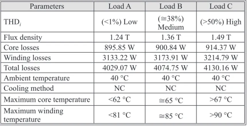
Table 3. The thermal FEA report of the transformer according to the load conditions
Parameters Load A Load B Load C
THDi (<1%) Low (≅38%) Medium (>50%) High
Flux density 1.24 T 1.36 T 1.49 T Core losses 895.85 W 900.84 W 914.37 W Winding losses 3133.22 W 3173.91 W 3214.79 W Total losses 4029.07 W 4074.75 W 4130.16 W Ambient temperature 40 °C 40 °C 40 °C Cooling method NC NC NC
Maximum core temperature <62 °C ≅65 °C >67 °C
Maximum winding
temperature <81 °C ≅85 °C >90 °C
The temperature values of the transformer core determined as 62 °C for linear load (Load A) condition. For non-linear load conditions, it increases by 3 °C and reaches to 65 °C for Load B, and it is higher than 67 °C for Load C. Furthermore, as the amplitudes and frequency values of harmonic components of the current flowing through the transformer windings increase, windings losses become higher than the total core losses as seen in fig. 7. Therefore, it should be considered that the temperature values above 90 °C may cause prob-lems in the insulation materials of the transformer and that the life of the transformer may be affected by excessive non-linear loads. In addition, the cooling system test can be effectively performed by the FEA during the design phase, thus required cooling system revisions can be obtained.
In natural convection cooling conditions, due to the increase of THD value of non-linear load, abnormal temperature increase occurs in both core and windings of dry-type trans-former. Using the forced air-cooling system in order to reduce this abnormal temperature in-crease improves the cooling capacity. Depending on the air-flow ventilation using forced-air
cooling system can remove additional heat caused by Load C, and thus, possible damages on transformer can be prevented. CFD analysis of the transformer has been carried out for 0.5 m/s air-flow ventilation with ANSYS-FLUENT software with the temperature distribution in seen fig. 8. Where the air ventilation is de-fined in the opposite direction of the z-axis and the ambient temperature is assumed to be 40 °C, so the tempera-ture of the windings can be reduced from 90 °C to 80 °C. More cooling can be achieved by increasing the air-flow rate. Thus, the temperature of dry type transformers can be main-tained at safe levels by increasing forced air-cooling capacity, especially due to the increase in non-linear loads, which have become more common in recent years.
First suggestion is based on modifying the cooling system of the transformer oper-ating under non-linear load. Increasing the air-flow rate or using higher capacity cooling system is considered to remove additional heat caused by Load C. Thus, possible damages on trans-former can be prevented. Therefore, the air-flow rate of the forced air-cooling system has been used in the dry type transformer has been increased with 0.5 m/s steps and thermal analysis of the transformer has been performed for each air-flow rate with ANSYS-FLUENT software. The obtained results are given in fig. 9 for the air-flow rate values with the parametric simulation. It is seen from these results that, even with forced air-cooling system with 1.5 m/s air-flow rate, the excessive temperature increase occurs in the transformer because of the non-linear load and this cannot be removed completely.
Second suggestion for reducing transformer temperature for the non-linear loads is modifying size of the transformer core and winding. The windings and the core volume to ob-tain same temperature level for three load types are given in fig. 10.
It is seen from the figure that, although the core volume for Load A is about 122 dm3,
it is approximately 140 dm3 for Load C. On the other hand, while the volume of the transformer
Figure 7. Temperature distribution of the windings; (a) Load A, (b) Load B, (c) Load C
(for color image see journal web site)
(a) (b) (c)
Figure 8. Temperature distribution of the transformer with the forced air-cooling under the Load C
windings is 135 dm3, it is 210 dm3 for Load C. Since the harmonic components of the current
cause additional heating, total volume of the transformer should be increased for Load C. Conclusions
This study is remarkable, because in recent years, distribution transformers often have to operate with the non-linear loads, which draw currents with harmonic components from transformers. These harmonic components cause abnormal losses both on the transformer core and the windings. In this context, the thermal effects of the transformer of a certain power rate have been determined according to different load conditions. It is clearly seen from the FEA based simulation results that the total losses increase under the non-linear load with the high THD values. This shows that harmonic components have an important effect on the winding losses and makes them major heat sources. Temperature distributions also varies according to the load conditions, and there is a relation between the current THD value and the temperature rise. Thus, the influence of non-linear loads on both the transformer losses and temperature values can be easily determined with FEA in modern design concept. Many parameters of the transformer can be inspected with electromagnetic and thermal modelling before the proto-type is produced. Since the performance of the cooling system can also be tested with CFD analysis, the thermal requirements such as the decision of the optimal cooling method can be also determined. Consequently, a suggestion has been presented in order to reduce transformer temperature under the non-linear load condition (according to Load C) such as employing the transformer cooling system for the dry type isolation transformers. Also proposed method can be extended to the cast resin distribution transformers.
Finally, the points highlighted in this study are as follows.
y Thermal behavior and cooling requirement of isolation transformers are determined by FEA simulation depending on load conditions.
y For the cooling of the core and windings performance analysis based on air-flow rate is per-formed and fig. 9 is obtained for the 500 kVA dry type isolation transformer under Load C. Thus, additional forced air cooling is recommended.
y According to the results of FEA simulations, graph of change in core and winding volume according to load type of transformers in more realistic conditions is proposed.
Nomenclature
Ac – cross-sectional area of
the transformer core
b(t) – magnitude of the flux density
Bpk – peak flux density
Cp – specific heat capacity
C – thermal capacity
Figure 9. Cooling performance depend on the air-flow rate
under the Load C with 150% load Figure 10. Core and winding volume according to the load type
40 50 60 70 80 90 100 0.0 0.5 1.0 1.5 2.0 2.5 Cooling performance T [° C]
Air-flow rate [ms–1] Load type
A B C Windings Core Volume [dm 3] 250 225 200 175 150 125 100 75 50 25 0
e(t) – induced voltage
f – operating frequency
hc – actual heat transfer coefficient
h – harmonic order.
Kc – eddy-current coefficient
Ke – abnormal coefficient
Kf – form factor of the transformer
excitation voltage
Kh – hysteresis coefficient
k – thermal conductivity
K – specific parameters of the core material
N – number of turns
Pc – classical eddy-current loss
Pe – abnormal eddy-current loss
Pfe – total core losses
Ph – hysteresis loss
p – the pressure, [Pa]
Pv – volumetric core loss
Pw – winding losses of the transformers
q – heat flux
Q – the volumetric density of the heat source
Rac(p) – AC resistance values of the primary
winding
Rac(s) – AC resistance values of the secondary
winding
Ta – temperature at a point far from the surface
T – temperature gradient
u – fluid velocity in the x-axe, [ms–1]
v – fluid velocity in the y-axe, [ms–1]
w – fluid velocity the z-axe, [ms–1]
x – Steinmetz coefficient
y – represents the current I or voltage U
Greek symbols
α – specific parameters of the core material β – specific parameters of the core material
γc – mass density of the core material
γ – Stefan-Boltzman constant δ – core material thickness ε – thermal radiation coefficient
ρe – resistivity of the core material
Subscripts a – ambient ac – alternative current dc – airect current e – electrical p – pirmary s – secondary Acronyms
FEA – finite element analysis THD – total harmonic distortion
References
[1] Balci, S., et al., Loss Behavior of the Dry-Type Power Transformer According to the Load Type, Proceeding, 5th
European Conference on Renewable Energy Systems (ECRES), Sarajevo, Bosnia and Herzegovina, 2017, pp. 49 [2] Digalovski, M., et al., Impact of Current High Order Harmonic to Core Losses of Three-Phase
Distribu-tion Transformer, Proceedings, IEEE Eurocon, Zagreb, Croatia, 2013, pp. 1531-1535
[3] Loizos, G., et al., Flux Distribution Analysis in Three-Phase Si-Fe Wound Transformer Cores, IEEE
Transactions on Magnetics, 46 (2010), 2, pp. 594-597
[4] Silva, D. C. L. et al., Contributions to the Study of Energy Efficiency in Dry-Type Transformer under
Nonlinear Load, Proceedings, IEEE 24th International Symposium on Industrial Electronics (ISIE),
Buz-ios, Brazil, 2015, pp. 456-461
[5] Taher, M. A., et al., K-Factor and Transformer Losses Calculations under Harmonics, Proceedings, IEEE
18th International Middle East Power Systems Conference (MEPCON), Cairo, Egypt, 2016
[6] ***, IEEE Standard C57.110-1998, IEEE Recommended Practice for Establishing Transformer Capabil-ity when Supplying Non-sinusoidal Load Currents, IEEE Publications, 445 Hose Lane, P.O Box 1331, Piscataway, Nj 08855-1331, USA, 1998
[7] Arjona, M. A., et al., Thermal Analysis of a Dry-Type Distribution Power Transformer Using FEA, Proceedings, IEEE 2014 International Conference on Electrical Machines (ICEM), Berlin, Germany, 2014, pp. 2270-2274 [8] Ghahfarokhi, P. S., et al., Hybrid Thermal Model of a Synchronous Reluctance Machine, Case Studies in
Thermal Engineering, 12 (2018), Sept., pp. 381-389
[9] Alyozbaky, O. S., et al., A Novel Method to Enhance the Core Design of Power Transformers Using Particle Swarm Optimization (PSO) Technique, International Journal of Simulation: Systems, 19 (2019), 6, pp. 1-10 [10] Xingmou, Liu, X., et al., Numerical Research on the Losses Characteristic and Hot-Spot Temperature of
Laminated Core Joints in Transformer, Applied Thermal Engineering, 110 (2017), Jan., pp. 49-61 [11] Ding, L., et al., Temperature Field Simulation Research on the Leakage, Thermal Science, 22 (2018),
Suppl. 2, pp. S649-S654
[12] Balci, S., The Analysis, Design and Implementation of the Medium Frequency Power Transformer with the Nanocrystalline Core Material (in Turkey), Ph. D. thesis, Gazi University-Institute of Science and Technology, Gazi, Turkey, 2016
[13] Upadhyayl, G., et al., FEM Based No-Load Loss Calculation of Triangular Wound Core Transformer,
Proceedings, 1st IEEE International Conference on Power Electronics. Intelligent Control and Energy Systems (ICPEICES-2016), Delhi, India, 2016, pp. 1-4, 4-6
[14] Battal, F., et al., An Analysis on Vibration Effects of Dry Type Transformers Operating under Nonlinear Load Conditions (in Turkey), GU J. Sci., Part C, 7 (2019), 3, pp. 729-740
[15] Salam, S. M., et al., New Approach to Develop a Template Based Load Model that can Dynamically Adopt Different Types of Non-linear Loads, Proceedings, IEEE International Conference on Electrical, Computer and Communication Engineering (ECCE), Cox’s Bazar, Bangladesh, 2017, pp. 708-712 [16] Jabbar, R. A., et al., Impacts of Harmonics caused by Personal Computers on Distribution Transformers,
Proceedings, IEEE 3rd International Conference on Electrical Engineering, ICEE ‘09, Lahore, Pakistan, 2009
[17] Matanov, N., et al., Electrical Loads and Profiles of Public Buildings, Proceedings, IEEE 15th
Interna-tional Conference on Electrical Machines, Drives and Power Systems (ELMA), Sofia, Bulgaria, 2017, pp. 233-237
[18] ***, IEC 61000-2-2:2002, Electromagnetic Compatibility (EMC) – Part 2-2: Environment - Compati-bility Levels for Low-Frequency Conducted Disturbances and Signaling in Public Low-Voltage Power Supply Systems, https://webstore.iec.ch/publication/4133, (2002)
[19] Ciufu, L., et al., Experimental Mitigation Techniques to Reduce the Total Harmonic Distortion of Low
Voltage Non-Linear Power Sources, Proceedings, 10th International Symposium on Advanced Topics in
Electrical Engineering (ATEE), Bucharest, Romania, 2017, pp. 138-141
[20] Tripathi, A., et al., Investigations on Optimal Pulse Width Modulation to Minimize Total Harmonic Dis-tortion in the Line Current, IEEE Transactions on Industry Applications, 53 (2017), 1, pp. 212-221 [21] Najafi, A., Iskender, I., A Novel Concept for Derating of Transformer under Unbalance Voltage in the
Presence of Non Linear Load by 3-D Finite Element Method, Electr. Eng., 97 (2015), 1, pp. 45-56 [22] Steinmetz, C. P. On the Law of Hysteresis, In American lnstitute of Electrical Engineers Transactions, 9
(1892), pp. 3-64
[23] Sefa, I., et al., Core Losses of PWM Excited Inverter Transformers with Finite Element Method,
Proceed-ings, 7th International Conference on Technical and Physical Problems of Power Engineering, Near East University Lefkosa, TR Northern Cyprus, 2011
[24] Balci, S., et al., Core Material Investigation of Medium-Frequency Power Transformers, Proceedings,
IEEE-16th International Power Electronics and Motion Control Conference and Exposition (PEMC),
An-talya, Tukey, 2014, pp. 861-866
[25] Sefa, I., et al., A Comparative Study of Nanocrystalline and SiFe Core Materials for Medium-Frequency Transformers, Proceedings, IEEE International Conference–6th Edition, Electronics, Computers and Ar-tificial Intelligence (ECAI), Bucharest, Rumania, 2014, pp.43-48.
[26] Yao, X. G., et al., Influence of Switching Frequency on Eddy-Current Losses in a Phase, Three-Limb Transformer Core Subjected to PWM Voltage Excitation, Proceedings, IEEE Powereng Confer-ence, Setubal, Portugal, 2007, pp. 324-329.
[27] Villar, I., et al., Transient Thermal Model of a Medium Frequency Power Transformer, Proceedings,
IEEE-34th Annual Conference of Industrial Electronics (IECON), Orlando, Fla., USA, 2008, pp. 1033-1038
[28] Lienhard, H. J., A Heat Transfer Textbook, Phlogiston Press, Cambridge, UK, 2004, pp. 1-6
[29] Raeisiana, L., et al., Thermal Management of a Distribution Transformer: An Optimization Study of the Cooling System Using CFD and Response Surface Methodology, Electrical Power and Energy Systems,
104 (2019), Jan., pp. 443-455
[30] Hannun, R. M., et al., Heat Transfer Enhancement from Power Transformer Immersed in Oil by Earth Air Heat Exchanger, Thermal Science, 23 (2019), 6A, pp. 3591-3602
[31] Balci, S., et al., An Analysis on Cooling Requirements of the High Power Medium Frequency Inductors,
Proceedings, IEEE 12th International Conference on Compatibility, IEEE Power Electronics and Power Engineering (CPE-POWERENG 2018), Doha, Qatar, 2018
[32] Mayda, M., An Efficient Simulation-Based Search Method for Reliability-Based Robust Design Optimi-zation of Mechanical Components, Mechanika, 23 (2017), 5, pp. 696-702
Paper submitted: July 6, 2019 Paper revised: September 15, 2019 Paper accepted: September 22, 2019
© 2020 Society of Thermal Engineers of Serbia Published by the Vinča Institute of Nuclear Sciences, Belgrade, Serbia. This is an open access article distributed under the CC BY-NC-ND 4.0 terms and conditions
![Figure 1. Flowchart of the thermal coupled FEA [31]](https://thumb-eu.123doks.com/thumbv2/9libnet/4573090.83943/6.892.152.445.501.903/figure-flowchart-thermal-coupled-fea.webp)
![Figure 3. Co-simulation circuits; (a) Load A, (b) Load B, (c) Load C [14]](https://thumb-eu.123doks.com/thumbv2/9libnet/4573090.83943/7.892.387.740.492.1057/figure-co-simulation-circuits-load-load-load.webp)
![Figure 4. Harmonic spectrums of the load currents; (a) Load A, (b) Load B, (c) Load C (c) (a) (b) 0.00 0.25 0.50 0.75 1.00 1.25 1.50Spectrum [kHz]Spectrum [kHz]800.00700.00600.00500.00400.0030](https://thumb-eu.123doks.com/thumbv2/9libnet/4573090.83943/8.892.152.731.222.806/figure-harmonic-spectrums-currents-load-load-spectrum-spectrum.webp)