Vol. 135 (2019) ACTA PHYSICA POLONICA A No. 4
Special Issue of the 8th International Advances in Applied Physics and Materials Science Congress (APMAS 2018)
Non-Invasive 3D Optical Measurement of Round Surfaces
H. Kurtuldu
a∗, G. Durkaya
band B. Çetin
caBaskent University, Department of Biomedical Engineering, Ankara, Turkey bAtilim University, Department of Metallurgical and Materials Engineering, Ankara, Turkey
cFNSS Defense Systems Co. Inc., Engineering and Research Department, Ankara, Turkey Precise measurement of wear profiles in large areas of round surfaces such as shafts, suspension bars and high-deviation geometry surfaces is a challenge in manufacturing engineering. An optical measurement method is developed to overcome this challenge. This method, relying on angular reconstruction of scattered light profiles, is used for the measurement of irregular wear in quality testing of round surfaces which provides information on estimating the surface lifetime after prolonged use. This approach achieves a 3D depth accuracy better than 50 µm in suspension bars with diameters up to 50 mm from an imaging distance of 250 mm.
DOI:10.12693/APhysPolA.135.746
PACS/topics: 3D optical measurement, digital image processing, rod, wear, non-invasive measurement
1. Introduction
The wear is the material loss of the surface of a solid body under mechanical forces during relative material motion. Wear may occur due to many factors such as unsuitable part design, overpressure, contact area, insuf-ficient lubrication, environmental and material proper-ties. Wear is a permanent service condition in engineer-ing applications with many economic and technical con-sequences [1]. From an economical point of view, the cost of wearing is estimated to vary between 1% and 4% of the gross national product of an industrialized nation. The pin-on-disk test, a standard test in many laborato-ries, mimics mechanical components in firm conditions according to the ASTM G99-95 standard. This tech-nique is invasive since both the pin and surface wear at the same time with different rates. It is also not appli-cable for round surfaces. White light interferometry is a non-contact optical technique that allows measurement of surface profiles with high speed and accuracy using phase shift of light [2]. However, like other optical and numerical methods reported in the literature [3, 4], this interferometric method is difficult to use for the wear measurement of large round surfaces. In this study, a novel measurement system is developed to study wear on large (>1 mm) cylindrical parts. It uses angular slicing of optical images with digital image optimization to create 3D model of the part and enable precise measurement of non-uniform wear.
2. Experimental procedure
The system developed to measure wear on cylindrical geometries is delineated in Fig. 1a, and an optical scheme of the system is presented in Fig. 1b. The round bar is
∗corresponding author; e-mail: [email protected]
Fig. 1. (a) Measurement system and (b) an optical scheme of the system, (c) cross-section view of the round bar (red arc shows the quadrant where the analysis is performed).
fixed to a chuck which is rotated around the bar axes. The bar is illuminated from bottom and top (off-angle) using white LED sources. A 5 MP scientific complemen-tary metal-oxide-semiconductor (CMOS) camera with a pixel size of 3.2 µm, and a zoom lens with a working distance of 175 mm and numerical aperture of 0.035 are utilized for imaging. The imaging system is located at the top of the bar vertically to the rotation plane. It
Non-Invasive 3D Optical Measurement of Round Surfaces 747 tures images of the bar surface between the closest and
farthest optically visible points as shown by the red arc quadrant in Fig. 1c. In this method, light from bottom provides silhouette image which is used to determine the border edge of the bar. The off-angle top illumination provides the image of the amplitude distribution along the arc to determine the distance of the surface from the camera sensor.
The rotation chuck is attached to a 10× reducer which is driven by a stepper motor. A microcontroller and driver unit are programmed by C language for motor control. Numerical analysis routines for image process-ing is also developed in C usprocess-ing freely available packages. The bar is rotated around its axes by the chuck and the quadrant amplitude profile is recorded at each rotation in 1-degree intervals. After registering 360 profiles around the bar to each other, a 3D depth profile of the bar is obtained in cylindrical coordinates. The system is cali-brated by a hardened steel rod of radius 25 mm before each measurement. A new suspension bar (50 mm in di-ameter) of an armored vehicle is used for the wear tests. The bar is initially measured in the system before apply-ing any wearapply-ing process. Then, it is intentionally worn non-uniformly in the setup shown in Fig. 2. In this setup, a wear head is placed on a linear stage and controlled by a hydraulic piston. The head exerts controlled forces to the different regions of the bar surface while the bar is stationary or rotating. After the wearing process, the bar is measured in the system again to analyze the wear.
Fig. 2. Tribo-test rod wear setup.
3. Results and discussion
The surface profiles of the suspension bar before and after the intentional wear process is compared to mea-sure the amount of wear on the surface. The 3D profiles are delineated in Fig. 3a and b for non-worn and worn bar surfaces, respectively. A 3D overlap image (Fig. 3c) provides comparison of both cases and enables identifi-cation of worn regions. The wear is clearly not uniform and the scratches around the bar correspond to higher material loss.
Fig. 3. 3D optical measurements for (a) non-worn (be-fore wear application), (b) worn (after wear) rod sur-faces, and (c) overlap of both.
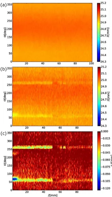
Fig. 4. Colormap representations of (a) non-worn, (b) worn surface and (c) difference between them. The measurements in the radial direction are given as a func-tion of the distance and the angle.
748 H. Kurtuldu, G. Durkaya, B. Çetin The side surface in radial direction is analyzed for a bar
length of 100 mm, as shown in Fig. 4. The horizontal axis is the distance along the rod and the vertical axis is the angle around the bar. The colormap indicates the change in the bar radius. Before any wear process, the radial map is quite uniform with an average radius of 24.95 mm (Fig. 4a). After the wear test, the fluctuation in radius is as much as 150 µm over the surface (Fig. 4b). For better comparison, the difference between worn and non-worn colormaps is calculated, as presented in Fig. 4c. The measurement resolution in the radial direction is better than 50 µm. Two bright lines on both sides of the bar are probably corresponding to the regions where the tribo-test wear head exerted more force.
4. Conclusion
A novel 3D optical measurement technique is devel-oped to analyze wear on large cylindrical surfaces. The method is tested with intentionally worn steel rods of 50 mm diameter. The wear profile is successfully ob-tained with a resolution of 50 µm. The system presented in this study can easily be modified to include much smaller or larger cylindrical parts for precise measure-ment of wear.
Acknowledgments
Authors would like to thank the Scientific and Tech-nological Research Council of Turkey for research grant #116M131.
References
[1] R.G. Bayer, Mechanical Wear Fundamentals and Testing, 2nd ed., Marcel Dekker, New York 2004. [2] A. Devillez, S. Lesko, W. Mozer,Wear 256, 56 (2004). [3] R. Danzl, F. Helmli, S. Scherer, in: Proc. 10th Int. Conf. of the Slovenian Society for Non-Destructive Testing, Application of Contemporary Non-Destructive Testing in Engineering, 2009, p. 484. [4] J. Jurkovic, M. Korosec, J. Kopac,Int. J. Machine