CHARACTERIZATION OF ASSEMBLY AND
SELF-HEALING OF PEPTIDE AMPHIPHILES BY ATOMIC FORCE
MICROSCOPY
A THESIS SUBMITTED TO
GRADUATE SCHOOL OF ENGINEERING AND SCIENCE OF BILKENT UNIVERSITY
IN PARTIAL FULFILLMENT OF THE REQUIREMENTS FOR THE DEGREE OF
MASTER OF SCIENCE IN
MATERIALS SCIENCE AND NANOTECHNOLOGY
By
FATMA BEGÜM DİKEÇOĞLU
CHARACTERIZATION OF ASSEMBLY AND
SELF-HEALING OF PEPTIDE AMPHIPHILES BY ATOMIC FORCE
MICROSCOPY
By Fatma Begüm Dikeçoğlu,October, 2017
We certify that we have read this thesis and that in our opinion it is fully adequate, in scope and in quality, as a thesis for the degree of Master of Science.
Aykutlu Dana (Advisor)
Mustafa Özgür Güler (Co-advisor)
Memed Duman
Çağlar Elbüken
Approved for the Graduate School of Engineering and Science:
Ezhan Karaşan
i
ABSTRACT
CHARACTERIZATION OF ASSEMBLY AND
SELF-HEALING OF PEPTIDE AMPHIPHILES BY ATOMIC FORCE
MICROSCOPY
Fatma Begüm Dikeçoğlu
MSc in Materials Science and Nanotechnology Advisor: Aykutlu Dana
Co-advisor: Mustafa Özgür Güler
October, 2017
Biological feedback mechanisms exert precise control over the initiation and termination of molecular self-assembly in response to environmental stimuli, while minimizing the formation and propagation of defects through self-repair processes. Peptide amphiphile (PA) molecules can self-assemble at physiological conditions to form supramolecular nanostructures that structurally and functionally resemble the nanofibrous proteins of the extracellular matrix (ECM), and their ability to reconfigure themselves in response to external stimuli is crucial for the design of intelligent systems. In this thesis, we investigated the real-time self-assembly, deformation, and self-healing of ECM-mimetic PA nanofibers in aqueous solution by using a force-stabilizing double-pass scanning AFM imaging method to disrupt the self-assembled peptide nanofibers in a force-dependent manner. We showed that nanofiber damage
ii
occurs at tip forces exceeding 1 nN, and that the damaged fibers subsequently recover under sub-nN tip forces. Fiber ends occasionally failed to reconnect following breakage and continue to grow as two individual nanofibers. Energy minimization calculations of nanofibers with increasing cross-sectional ellipticity (corresponding to varying levels of tip-induced fiber deformation) supported our observations, with high-ellipticity nanofibers exhibiting lower stability compared to their non-deformed counterparts. As a result, tip-mediated mechanical forces can provide an effective means of altering nanofiber integrity and visualizing the self-recovery of PA assemblies.
Keywords: Self-assembly, self-healing, peptide amphiphile nanofibers, atomic force microscopy
iii
ÖZET
PEPTİT NANOFİBER YAPILARININ ATOMİK KUVVET
MİKROSKOPU İLE INCELENMESİ
Fatma Begüm Dikeçoğlu
Malzeme Bilimi ve Nanoteknoloji, Yükesek Lisans Tez Danışmanı: Aykutlu Dana
Tez Eşdanışmanı: Mustafa Özgür Güler
Ekim, 2017
Biyolojik geribildirim mekanizmaları, çevresel uyarılara yanıt olarak moleküllerin kendiliğinden bir araya gelmelerinin başlatılması ve sona erdirilmesi üzerinde tam kontrol sağlarken, kendi kendilerini yenileyebilme mekanizmaları yoluyla bozuklukların oluşumunu ve yayılmasını en aza indirir. Peptit amfifil (PA) molekülleri yapısal ve işlevsel olarak hücre dışı matrisin (ECM) nanofibral proteinlerine benzeyen supramoleküler nano yapılar oluşturmak için fizyolojik koşullarda kendiliğinden bir araya gelmeleri ve dışardan gelen uyarıcılara yanıt olarak kendilerini yeniden yapılandırabilme özellikleri akıllı sistemlerin tasarlanmasında önemli bir yere sahiptir, Bu tezde, kuvvet dengeleyen çift geçişli tarama AFM görüntüleme yöntemi kullanarak, su ortamında gerçek zamanlı olarak ECM mimetik peptit nanofiberlerin kendiliğinde bir araya gelmeleri, kuvvete bağlı olarak deforme olup yeniden kendilerini iyileştirebilmelerini inceledik. Nanofiber hasarının 1 nN'yi aşan tip kuvvetlerinde oluştuğunu ve hasar gören liflerin daha sonra nN altındaki tip
iv
kuvvetleriyle tarama yapıldığında iyileştiğini gözlemledik. Kırılma olan yerlerden fiber uçları genel olarak tekrar birleşmek yerine birbirlerine parallel iki ayrı fiber olarak büyüme gösterdiler. Enine kesit alınarak nanofiberlerin artan eliptisitilerinin enerji minimizasyon hesaplamaları yapıldı ve yüksek eliptisiteli nanofiberlerin, deforme olmayan eşdeğerleriyle kıyasla daha düşük kararlılık gösterdikleri görüldü. Sonuç olarak, tip kaynaklı mekanik kuvvetler, nanofiber bütünlüğünü değiştirmede ve kendilerini iyileştirmelerini gözlemlemede etkili bir yol olduğu söylenebilir.
Anahtar Kelimeler: Kendiliğinden bir araya gelme, kendiliğinden iyileşme, peptit amfifil nanofiber, atomik kuvvet mikroskopu
v
ACKNOWLEDEMENT
I have spent two years in a great research environment with many valuable people. First of all, I would like to express my deepest appreciation to my thesis advisor Prof. Aykutlu Dana for accepting me to his research group and his patience, guidance, knowledge and support, without him I would not perform any of these experiments. I am also grateful to Prof. Mustafa Özgür Güler and Prof. Ayşe Begüm Tekinay for their guidance, encouragement and support throughout my master thesis studies. This work could not be accomplished without their precious contribution.
I would like to express my special thanks to Dr. Ahmet Emin Topal and Alper Devrim Özkan, whose support and motivation contributed a lot to this work.
I would like to thank Özge Uysal, Dr. Elif Arslan, Dr. Gülistan Tansık and Mustafa Beter for their contribution to my studies and most importantly for their worthy friendship.
It was great to know you and work with you all: Dr. Ruslan Garifullin, Dr. M. Aref Khalily, Dr. Melis Şardan Ekiz, Dr. Göksu Çınar, Egemen Deniz Eren, Meryem Hatip, Nurcan Haştar, İdil Uyan, Dr. Özlem Erol, Zeynep Orhan, Seren Hamsici, Nuray Gündüz, Fatih Yergöz.
My sincere thanks also goes to Oya İlke Şentürk, Deniz Yıldız, Abdurrahman Türksoy, Abdüllatif Önen, Zehra Irem Yıldız, Dr. Zeynep Aytaç, Dr. Aslı Çelebioğlu, Behide Saltepe, Seylan Ayan, Tuğçe Önür for their valuable friendships and creating such a warm working environment.
vi
I would like to extend my speacial thanks to Mehdi Ramezani for always cheering me up and for providing me the most unforgettable memories to my life in UNAM. I would like to thank Mrs. Zeynep Erdoğan for her technical contribution to my thesis. I also thank to Suna Temiz who has always given me positive energy with her cheerful laughs.
I am deeply indebted to my dearest friend M.A.Üreten for his support and belief in me not only during my master but also during my undergraduate years.
Last but not least, I owe my most profound gratitude to my family, my mother Nesrin Dikeçoğlu, who is the most devoted to her children undoubtedly, and my father Kadir Dikeçoğlu for their unconditional love and support they gave for my whole life and my super-brother Enver Güneş Dikeçoğlu, who always be there for me for his endless support, unquestionable belief in me.
vii
CONTENTS
ABSTRACT ... i ÖZET... iii ACKNOWLEDEMENT ... v LIST OF FIGURES ... x LIST OF TABLES ... xv Abbreviations ... xvi CHAPTER 1 ... 1 1. INTRODUCTION ... 11.1 Self-assembly of Peptide Nanostructures... 2
1.2 Peptide Amphiphiles ... 4
1.3 Biomedical Applications of Peptide Amphiphiles ... 6
1.4 Characterizations of Peptide Amphiphiles ... 8
1.4.1 Atomic Force Microscopy (AFM) ... 10
1.4.1.1 Working Principle of AFM ... 12
1.4.1.2 Imaging Modes ... 14
Static mode: Contact mode ... 14
Dynamic mode: Intermittent-contact (tapping) mode and non-contact mode ... 15
1.4.1.3 Force Spectroscopy ... 15
viii
2. FORCE AND TIME DEPENDENT SELF-ASSEMBLY, DISRUPTION AND
SELF-HEALING OF SUPRAMOLECULAR PEPTIDE AMPHIPHILE
NANOFIBERS ... 17
2.1 INTRODUCTION ... 18
2.2 EXPERIMENTAL SECTION ... 21
2.2.1 Materials ... 21
2.2.2 Synthesis of Peptide Amphiphiles (PA) Molecules ... 22
2.2.3 Liquid Chromatography and Mass Spectrometry (LC-MS) ... 23
2.2.4 Preparative High Performance Liquid Chromatography (Prep-HPLC) ... 23
2.2.5 Circular Dichroism (CD) ... 23
2.2.6 Nile Red Assay ... 24
2.2.7 Transmission Electron Microscopy (TEM) ... 25
2.2.8 Scanning Electron Microscopy (SEM) ... 25
2.2.9 Energy Minimization (EM) Simulations ... 25
2.2.10 Sample Preparation and Atomic Force Microscopy (AFM) ... 27
2.3 RESULT AND DISCUSSION ... 29
2.3.1 Supramolecular Polymerization of Peptide Amphiphiles in Solution ... 29
2.3.2 Co-Assembly of Oppositely Charged Peptide Amphiphile Nanofibers ... 34
2.3.3 Disruption of PA Nanofibers under Loading Force ... 43
2.3.4 Self-healing Mechanism of the PA Nanofibers ... 50
ix
2.4 CONCLUSION ... 57 REFERENCES ... 58
x
LIST OF FIGURES
Figure 1. 1 Schematic illustration of the hierarchical self-assembly process involved in the formation of hydrogels from peptide molecules. (reproduced from Ref. 5 with permission from Royal Society of Chemistry) ... 3 Figure 1. 2 a) Molecular structure of a representative peptide amphiphile with four rationally designed chemical entities b) Self-assembly of PA molecules into a cylindrical micelle in water. (reproduced from ref. 7 (a) and ref. 8 (b) with permission from Wiley Online Library and Nature Communications, respectively) ... 5 Figure 1. 3 Self-assembled peptide amphiphiles used in biomedical applications. a) VEGF-mimetic peptide amphiphile presenting a high density of biological signals induces angiogenesis. b) Calcein-labeled cells are aligned on peptide amphiphile nanofiber bundles. c) Peptide amphiphile is conjugated to a drug through reversible covalent bonding. (Reproduced from Ref. 10 with permission from Royal Society of Chemistry) ... 7 Figure 1. 4 General characterization techniques for self-assembled peptide nanostructures (reproduced from ref. 11 with permission from …) ... 9 Figure 1. 5 a) The working principle of AFM and b) an AFM image of an amyloid fibril. ... 13 Figure 1. 6 Force regimes governing the AFM measurement. (adapted from ref X. with permission from …) ... 14 Figure 1. 7 Schematic diagram of the vertical tip movement during the approach and retract parts of a force spectroscopy experiment... 16 Figure 2. 1 Schematic description of the baseline-stabilized contact mode imaging system. An additional controller measures and subtracts the baseline using a
double-xi
pass scheme. Principle of baseline stabilized contact mode imaging. The tip is retracted from the surface and the deflection signal is measured and stored during the first pass, while the measured baseline is subtracted from the deflection signal and temperature and instrumental drifts are eliminated in the second pass. This double-pass imaging scheme allows stable imaging with sub nN forces over extended periods of time. 28
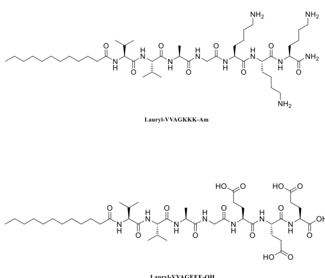
Figure 2. 2 Chemical structure of positively charged K3PA Lauryl-VVAGKKK-Am
and negatively charged E3PA Lauryl-VVAGEEE-OH ... 30
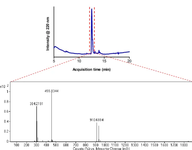
Figure 2. 3 Liquid chromatogram of positively charged Lauryl-VVAGKKK-Am and mass spectrum of corresponding peptide molecule. Mass data [M+H]+ (calculated) = 910.26, [M+H]+(observed) = 910.69, (observed [M+2H]+2/2 = 455.83, [M+3H]+3/3 = 304.22). ... 31 Figure 2. 4 Liquid chromatogram of negatively charged Lauryl-VVAGEEE-OH and mass spectrum of corresponding peptide molecule. Mass data [M-H]- (calculated) = 914.06, [M-H]-(observed) = 912.50, (observed [M-2H]-2/2 = 455.75, [M-3H]-3/3 = 304.49). ... 32 Figure 2. 5 Representative SEM (left) and TEM (right) images of co-assembled K3PA
and E3PA molecules to show PA nanofiber networks and individual nanofibers. .... 33
Figure 2. 6 Secondary structure analysis of K3PA, E3PA and mixed E3PA/K3PA
molecules through circular dichroism. ... 33 Figure 2. 7 Nile Red assay of E3PA, K3PA, and E3PA/K3PA showing critical micelle
concentration. The maximum emission wavelength of PAs decreases as their concentration increases. ... 34 Figure 2. 8 Representative deflection AFM images showing the nucleation and growth of co-assembled E3PA/K3PA nanofibers, measured under time-lapse imaging over a
xii
10 min period (in total 160 images were acquired). Time-lapse frames were measured at a scan rate of 1 frame per minute. ... 36 Figure 2. 9 Fiber elongation rate, as derived from each frame of the ten-minute image series. ... 37 Figure 2. 10 PA nanofibers nucleated and grown in situ. (within 2.5 hours). Representation of the formation mechanism of a net-like fiber network. When a fiber encounters with another, it ceases its elongation and cannot extend further (black arrows)... 38 Figure 2. 11 Representative deflection 10 minutes intermittent AFM images of K3PA
molecules on the mica surface showing rapidly bundle formation due to the electrostatic attraction between negatively charged mica layers and positively charged PAs ... 39 Figure 2. 12 Representative deflection AFM images of negatively charged E3PA
molecules that unabled to self-assemble on negatively-charged mica surface due to electrostatic repulsion within 3 hours. ... 39 Figure 2. 13 Observation of affinity of AFM tip movements onto nanofiber formation throughout time-lapse imaging ... 40 Figure 2. 14 a) General appearance of a mature PA nanofiber network. Scale bar: 1 µm b) Histogram of nanofiber thickness showing that the average fiber thickness is ca. 5 nm and a conical fiber model with diameter of 4.5 nm used in energy minimization simulations (inset images). ... 42 Figure 2. 15 a) Representative deflection AFM images of fiber deformation in response to increasing tip forces. b) Height and width profile of a single nanofiber (shown with
xiii
white arrow) undergoing tip-mediated disruption, calculated using five regions across the length of fiber. Scale bar: 100 nm. ... 45 Figure 2. 16 Representative force-curve measurement of co-assembled E3PA/K3PA
nanofibers fitted by JKR model with Igor Pro (AFM) software to calculate their average Young’s moduli. Inset image shows the histogram of the Young’s moduli of PA nanofibers which was found as 33 MPa on average. ... 46 Figure 2. 17 AFM height image, adhesion force mapping and histogram of adhesion force of co-assembled E3PA/K3PA nanofibers on mica surface, respectively ... 47
Figure 2. 18 a) Representative peptide nanofibers image used for force-displacement analysis of fiber breakage. b) Selection of force-distance curves of mica and E3PA/K3PA fibers, showing collapse events in the latter. ... 48
Figure 2. 19 a) Differential response of mica and a peptide nanofiber against tip-induced forces. b) Displacement derivative analysis showing that fiber breakage occurs around 0.7 nN of force. ... 49 Figure 2. 20 Deformation and self-healing of PA nanofibers under varying forces. Scale bar: 100 nm and the scan bars are same for all images. ... 52 Figure 2. 21 The self-healing process could be observed within ca. 40 min under lower (0.2 nN) forces. Scale bar: 100 nm and the scan bars are same for all images. ... 53 Figure 2. 22 Modeling of nanofiber deformation under tip-mediated forces. (a) Layer and fiber formation for theoretical studies. (b) Fiber deformation and the corresponding disruption in fiber integrity at higher tip forces, as modeled by increasing modified eccentricity values. Potential energy values increase greatly after a modified eccentricity of 0.25 and are not shown here. ... 54
xiv
Figure 2. 23 Representative snapshots of fiber deformation under force, as modelled by increasing modified eccentricity values. ... 56
xv
LIST OF TABLES
xvi
Abbreviations
AFM Atomic force microscopy
CD Circular Dichroism
DCM Dichloromethane
DIEA N,N-diisopropylethylamine
DMF N,N-Dimethylformamide
ECM Extracellular matrix
EM Energy minimization
Fmoc 9-Fluorenylmethoxycarbonyl
HBTU N,N,N′,N′-Tetramethyl-O-(1H-benzotriazole-1-yl) uronium hexafluorophosphate
HPLC High pressure liquid chromatography LC-MS Liquid chromatography-mass spectroscopy QTOF Quadrapole time of flight
SEM Scanning electron microscopy SPPS Solid phase peptide synthesis
SPM Scanning probe microscopy
TEM Transmission electron microscopy
TFA Trifluoroacetic acid
1
CHAPTER 1
2 1.1 Self-assembly of Peptide Nanostructures
Self-assembling processes are crucial for nanotechnology due to their ability to produce highly organized structures without any external interactions. Self-assembly can be found in a wide range of biological structures (i.e. proteins, peptides, cell membranes, nucleic acids) and leads to the formation of diverse and complex functional systems in multiple configurations. These complex structures inspire scientists to construct improved materials for various applications. Molecular self-assembly is a technique in materials design and involves the use of molecular components that naturally reorganize themselves using non-covalent interactions such as hydrogen bonding, hydrophobic, electrostatic and van der Waals interactions. Those electrostatic, hydrophobic and hydrophilic repulsive forces provide reversibility to the system, whilst binding forces including hydrogen bonding, van der Waals, ionic and dipole-dipole interactions increase the stability of the organized structure and determines its architecture.[1–3]
Self-assembling peptides have been discovered as very useful biological structures for biomedical applications due to their inherent biocompatibility and biodegradability. Self-assembly of peptides present unique features such as biomimicry, controllable biochemical and physical properties (i.e. size, conformation, hydrophobicity, bioactivity) as well as stability to the design of sophisticated biomaterials. Due to their simple structure and facile synthesis method, self-assembling peptide building blocks have gained attention from diverse research fields for the bottom-up fabrication of complex nanobiomaterials. Using solid phase peptide synthesis methods, it is possible to design sequences having robust functional and structural features to use in a number of applications.
3
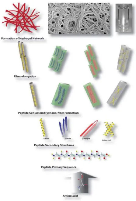
Self-assembling peptide scaffolds are formed through the hierarchical organization of individual peptide molecules that, in aqueous conditions, initially produce nanofibers and eventually develop into porous nanofiber networks (Figure 1.1).[2,4,5]
Figure 1. 1 Schematic illustration of the hierarchical self-assembly process involved in the formation of hydrogels from peptide molecules. (Reproduced from Ref. 5 with permission from Royal Society of Chemistry)
4 1.2 Peptide Amphiphiles
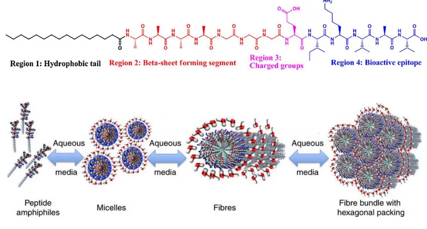
Peptide amphiphiles (PAs) are peptide-based molecules consisting of a hydrophobic tail group and hydrophilic amino acids, and were advanced by the Stupp group in particular.[6] PAs self-assemble in water into supramolecular one-dimensional (1D) high-aspect-ratio cylindrical nanostructures.[7] The chemical structure of PAs consists of four domains that assemble into well-defined supramolecular structures. These domains are the hydrophobic tail, which forms hydrophobic interactions and makes the molecule amphiphilic; a β-sheet forming peptide sequence, which assists in self-assembly by forming hydrogen bonds; charged amino acids, which increase the solubility of the peptide; and functional bioactive epitope, which are required for biological signaling (Figure 1.2a).[8] In aqueous solutions, individual PA molecules begin to aggregate and form spherical micelles due to hydrophobic interactions between alkyl chains. The peptide head groups are pulled away because of electrostatic repulsion and clusters of spherical micelles begin to merge with one another. This process continues until the formation of cylindrical nanostructures that aggregate into bundles and entanglements to form higher order structures (Figure 1.2b).[9]
5
Figure 1. 2 a) Molecular structure of a representative peptide amphiphile with four rationally designed chemical entities (Reproduced from ref. 7 with permission from National Academy of Sciences) b) Self-assembly of PA molecules into a cylindrical micelle in water. (Reproduced from ref. 8 with permission from Wiley Online Library)
a
6
1.3 Biomedical Applications of Peptide Amphiphiles
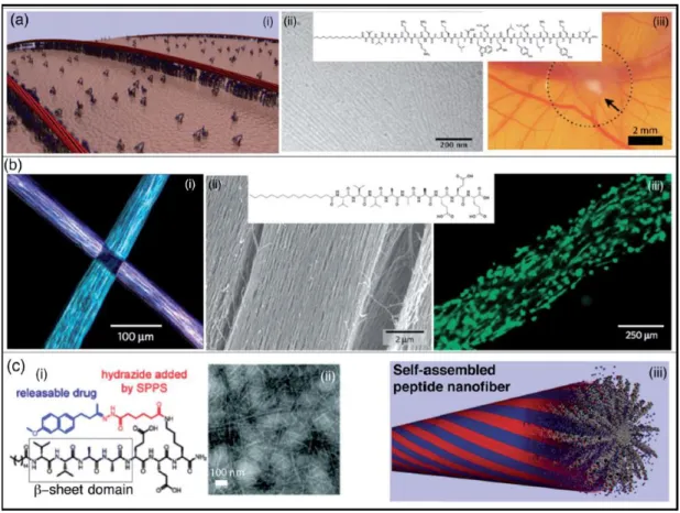
Peptide amphiphile (PA) molecules can be used as scaffolds that mimic the natural extracellular matrix (ECM) components due to their biocompatibility and biodegradability, and in this form they are commonly used in tissue engineering and regenerative medicine. In addition, biological signals on the surface of bioactive PAs offer great benefits such as adaptability to their environment, cell-specific targeting, or adhesion to cell receptors. Therefore PA molecules are attractive candidates for potential biomaterial development. PAs can also form gels by controlling their charges and are suitable for drug delivery.[10]
Webber and coworkers have designed a VEGF-mimetic PA that is capable of inducing angiogenesis and stimulating the proliferation, survival and migration of endothelial cells in vitro, while increasing tissue perfusion, supporting functional recovery and treadmill endurance, and enhancing the density of microcirculation in vivo (Figure 1.3a).[11] PA systems typically assemble in high-aspect ratio materials that are structurally similar to the protein components of the spinal cord, blood vessels and muscles. In addition, external forces can be used to promote fiber assembly in specific configurations; for example, heating-cooling cycles can trigger the assembly of PA nanofibers in ordered arrays, and the addition of cells to this mixture results in the formation of well-aligned macroscale assemblies containing both nanofiber and cells (Figure 1.3b).[12]
7
Figure 1. 3 Self-assembled peptide amphiphiles used in biomedical applications. a) VEGF-mimetic peptide amphiphile presenting a high density of biological signals induces angiogenesis. b) Calcein-labeled cells are aligned on peptide amphiphile nanofiber bundles. c) Peptide amphiphile is conjugated to a drug through reversible covalent bonding. (Reproduced from ref. 10 with permission from Royal Society of Chemistry)
8 1.4 Characterizations of Peptide Amphiphiles
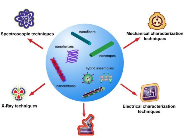
Owing to their complex and dynamic nature, self-assembled peptide nanostructures should be characterized through advanced sophisticated methods for the investigation of their chemical, physical, mechanical and electrical properties. These methods can be classified as spectroscopic, electrical, x-ray, mechanical and microscopic characterizations, which extend the application areas of functional materials.[13] Chemical and physical characteristics of peptides at the nanoscale, such as their bond properties (covalent and noncovalent interactions), molecular vibrations or electronic states, are investigated by applying spectroscopic methods. Common spectroscopic techniques used for the analysis of different self-assembled peptide amphiphile nanostructures are nuclear magnetic resonance (NMR), Fourier transform infrared spectroscopy (FTIR), fluorescence emission spectroscopy, Raman spectroscopy and circular dichroism.[14]
X-ray techniques are used to determine the interaction of high energy electromagnetic waves with self-assembled peptide nanostructures to reveal information about their size, shape and structural organization. X-ray diffraction (XRD) technique is used to identify molecular organization by considering the non-covalent interactions of the building blocks of self-assembled peptide nanostructures, as well as their unit cell parameters.[15] Electrical features such as the conductivity, resistance capacity or charge transfer characteristics of peptide nanostructures can be obtained by current (I)- voltage (V) measurements using electrodes connected to probe station systems.[16]
9
Figure 1. 4 General characterization techniques for self-assembled peptide nanostructures. (Reproduced from ref. 13 with permission from Nanotechnology)
The viscoelastic behavior of peptide nanostructures at concentrations above their gel formation threshold can be determined using oscillatory rheology. AFM-based nanoindentation methods can also be applied to self-assembled peptide nanostructures to reveal their nanomechanical properties. AFM nanoindentation techniques are widely used to determine the nanomechanical properties of peptide nanostructures, such as their Young’s modulus, adhesion, hardness, stiffness and elasticity, based on the force-distance curves acquired during scanning.[17] Investigating the inherent mechanical stability and rigidity of the peptide nanostructures may contribute to the design of functional materials.
10
Microscopic techniques have always been essential for the visualization of biological structures. Advances in the field of microscopy have facilitated the detailed observation of the formation, size, shape and even chemical structure of self-assembled peptide nanostructures, using different measurement techniques such as transmission electron microscopy (TEM), scanning electron microscopy (SEM), atomic force microscopy (AFM), fluorescence and other microscopy techniques. Since the aim of the present thesis is based on the AFM characterization of self-assembled peptide amphiphiles, the rest of this chapter will focus on the basics of atomic force microscopy.
1.4.1 Atomic Force Microscopy (AFM)
The atomic force microscope (AFM), invented by Binnig and colleagues in 1986,[18]
is probably the most versatile member of the scanning probe microscope (SPM) family and has been widely utilized in biological research due to its ability to acquire high-resolution, real-time images of biological samples under physiological conditions. AFM differs from other microscopic techniques in its use of a physical probe rather than light or particles to measure surface properties.[19] Accordingly, images are generated by the physical interaction of a sharp probe with the surface of the sample instead of photon or electron beams.
AFM has several advantages compared with the electron microscopy techniques, scanning electron microscope (SEM) or transmission electron microscope (TEM).[20] First of all, sample preparation in AFM does not require any pre-treatment such as labelling or staining of the specimen. Any type of sample can be measured in all kinds of environments under AFM, while SEM and TEM are usually operated under a vacuum environment and samples need to be conductive to prevent the excessive
11
deflection of electrons from their surface (biological samples are usually coated with a metallic layer such as gold or aluminium before imaging). Moreover, AFM has the ability to scan in the x, y, z directions, making it possible to obtain three-dimensional images and facilitating the height mapping of scanned areas. Table 1.1 shows the comparison of AFM with SEM and TEM with respect to some basic factors.[21] Table 1.1 Comparison of AFM with SEM and TEM.
AFM SEM TEM
Sample preparation little or none from little to a lot from little to a lot
Resolution 0.1 nm 5 nm 0.1 nm
Relative cost low medium high
Sample environment any Vacuum (SEM) or
gas (environmental SEM)
vacuum
Sample type conductive or insulating
conductive poor conductive
Time for image 2-5 minutes 0.1-1 minute 0.1-1 minute
Maximum field of view 100 µm 1 mm 100 nm
Maximum sample size unlimited 30 mm 2 mm
Measurements 3 dimensional 2 dimensional 2 dimensional
Apart from its function as a microscope, AFM can be used in spectroscopic measurements to find other properties such as the mechanical, electrical features of specimens. Due to this capacity, AFM has been used for a range of purposes in interdisciplinary research areas. In particular, the AFM has become a pioneering tool
12
for the biophysical characterizations of protein- and peptide-based molecules at the nanoscale to investigate their structural mechanisms in real-time in the solution state.
1.4.1.1 Working Principle of AFM
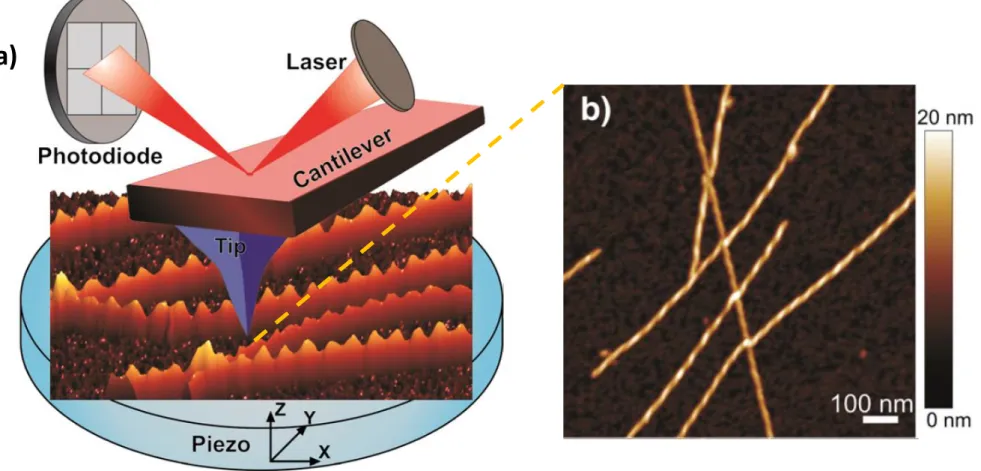
The principle-of-action of AFM is best likened to a blind person feeling the objects by touching with their fingers and mentally drawing an image of what they touch. In AFM, a tip attached to a flexible cantilever “touches” the sample surface to “sense” the surface morphology on an atomic scale.[19]
A laser is focused at the end of the cantilever to reflect onto a quadrupole photodiode. The tip is progressively brought into close proximity (few nanometers) of the sample surface. When the cantilever deflects due to the interaction of the tip and the sample, the laser spot exhibits a corresponding deflection, altering the photodiode signal. These deflections are calculated using changes in the voltage of photodiode and monitored by a controller. By monitoring the deflection of the cantilever, the force between the tip and the sample is measured during scanning. This force is a function of tip-sample separation and the material properties of the tip and the sample. A feedback mechanism is employed to adjust the tip-to-sample distance to maintain a constant force between the tip and the sample.[19,21,22]
13
Figure 1. 5 a) The working principle of AFM and b) an AFM image of an amyloid fibril. (Adapted with permission from Current Opinion in Colloid & Interface Science)
14 1.4.1.2 Imaging Modes
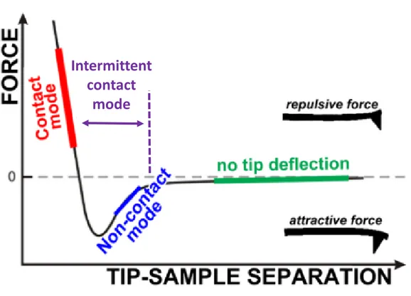
Depending on the region of the force field between the tip and sample during imaging, three working modes can be defined for atomic force microscopy. The forces experienced by the tip-cantilever ensemble can be separated into a repulsive short range force (< 1nm, Coulombic forces) and an attractive long range force (< 100 nm, van der Waals forces).
Figure 1. 6 Force regimes governing the AFM measurement. (Adapted with permission from Tends in Analytical Chemistry)
Static mode: Contact mode
This mode can also be called static mode or DC mode, where the AFM tip is constantly in contact with the sample and the deflection of the cantilever is kept constant during scanning by a feedback loop. Tip-sample interaction is in repulsive regime while the
Intermittent
contact
15
tip is moving across the surface. In this mode, the stiffness of the cantilever should be as low as possible. This mode is especially suitable for measurements of softer samples in liquid environment, as minimal force is applied to the sample surface. Silicon nitride microfabricated cantilevers bearing sharp pyramidal tips are commonly used for contact mode imaging on biological soft samples.[22,23]
Dynamic mode: Intermittent-contact (tapping) mode and non-contact mode In non-contact mode, an oscillating probe brought into the proximity of the surface but never touches it. The tip experiences only the van der Waals attractive forces on the surface of the sample. The amplitude of the cantilever oscillation is measured by keeping a constant frequency shift in the resonant frequency of the cantilever to operate the feedback loop during scanning. The major drawback of this mode is that it is difficult to use in liquid environments.[23]
Intermittent-contact mode, also called tapping mode, is another mode of operation. In this case, tip-sample interaction experiences both attractive and repulsive regimes during tip oscillation, the frequency of which can be used to measure the nature of the interaction. During this mode, the oscillating cantilever interacts with the sample by gently “tapping” onto the surface during scanning. In dynamic operation modes, higher spring constant values enable less noise and instabilities. A silicon cantilever and tip are usually used in dynamic operation modes.[22]
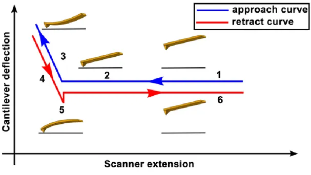
1.4.1.3 Force Spectroscopy
Force measurements by AFM are widely used to identify the nanomechanical properties of a sample through force-distance curves. A schematic representation of a force-distance curve is provided in Figure 1.7, illustrating the approach and retract
16
cycle of the tip during measurement. Typically, the AFM tip is gradually brought to the sample surface and indents it until the repulsive force experienced by the tip exceeds a pre-defined threshold, after which the tip is retracted. During the movement, deflection of the cantilever and the vertical position of the tip is recorded and then converted to a force-distance curve. Following this process, the recorded data is fitted with an appropriate model to provide the Young’s modulus (elastic moduli) value of the sample. Three fitting models are commonly used according to sample and tip properties: the Hertz model is the basic contact model for tip-sample interactions, but since the adhesion between the two surfaces is neglected in this model, the Johnson-Kendall-Roberts (JKR) and Derjaguin Muller-Toporov (DMT) models are more suitable for situations where the adhesion forces are significant.
Figure 1. 7 Schematic diagram of the vertical tip movement during the approach and retract parts of a force spectroscopy experiment. (Reproduced with permission from Polymer Science)
17
CHAPTER 2
2. FORCE AND TIME DEPENDENT
SELF-ASSEMBLY, DISRUPTION AND SELF-HEALING
OF SUPRAMOLECULAR PEPTIDE
AMPHIPHILE NANOFIBERS
18 2.1 INTRODUCTION
Self-assembly allows the building of complex, tunable, adaptable and highly sophisticated biomolecules in a broad range of three-dimensional (3D) configurations through bottom-up fabrication involving noncovalent interactions (i.e. hydrogen bonding, hydrophobic, electrostatic and van der Waals interactions).[1,8,24] Self-assembly is a process of organization through which disordered components of a system spontaneously associate to form well-defined architectures, and occurs ubiquitously in nature at all scales including molecules and living cells.[3,25] Peptide
amphiphiles (PAs) are versatile self-assembling biomaterials that form a variety of supramolecular one-dimensional (1D) nanostructures, with a predilection for cylindrical nanofibers. PAs are amphiphilic molecules that contain a hydrophobic alkyl tail linked to a hydrophilic amino acid sequence, the latter of which can be tailored for specific biomedical applications.[8][26][6] Noncovalent interactions between
these regions stimulate the formation of high-aspect-ratio nanostructures under certain environmental conditions (i.e. pH, ionic strength and temperature), with β-sheet secondary structures typically predominating in the resulting superstructure. Since self-assembly in PA molecules is governed by individually weak noncovalent interactions, PA nanostructures are highly dynamic and prone to partial disassembly and re-assembly. As such, PA assemblies may be disrupted in response to external factors and subsequently repaired through self-healing processes.[1,27,28] In contrast, polymers cannot undergo reassembly process without the addition of catalysts,[29] and
the ability of PA networks to self-assemble and self-repair through noncovalent interactions contributes greatly to their utility as biomedical materials. Owing to their dynamic composition, self-assembled PA nanofibers are also outstanding candidates
19
for investigating the self-assembly and self-healing mechanisms that occur in biological systems.
Due to their relevance to neurodegenerative disorders, the self-assembly and disassembly of amyloid fibrils and similar peptide nanostructures have been widely studied in the literature. Liang et al., for example, developed models for the formation of mature amyloid fibrils from preliminary aggregates through time-lapse fluorescence imaging.[30] Nucleation of a silk-elastin-like peptide (SELP) amyloid was directly observed using time-lapse atomic force microscopy in more recent studies; briefly, the assembly process was accelerated under nanomechanical stimulus and the growth direction of amyloid fibrils was influenced by the direction of AFM tip scanning.[31–
33] In addition, a mechanical manipulation method based on AFM was used to divide
self-assembled GAV-9 peptide nanofilaments into fragments that were subsequently repaired in situ.[34] Very recently, Karsai et al. conducted a detailed work on the formation and assembly mechanisms of amyloid fibrils under mechanical perturbation using time-dependent and high-resolution AFM imaging, where fibrils were fragmented in multiple directions by increased loads during scanning, and the repair of sectioned fibrils were followed in five-minute scan intervals.[35] Watanabe-Nakayama et al. also investigated fibril formation and elongation in an amyloid β-protein fragment (A β1-42), and found that environmental variables such as buffer salts can stimulate the formation of either straight or helical assemblies due to changes in the fibril extension process.[36] Similar studies on the effectiveness of environmental conditions in altering the self-assembly of protein structures have been performed by Dai et al., who showed that higher NaCl and MgCl2 salt concentrations stimulate the
20
reported that the structure of alpha-synuclein fibrils was strongly influenced by the ionic strength of the buffer environment.[37,38]
The self-healing process is crucial for the construction of new scaffolds in regenerative medicine, as the repair of the fibrillar elements of the ECM is important for the treatment of degenerative diseases that are caused by the progressive loss of matrix integrity. As such, a number of self-healing peptide hydrogels have previously been designed for applications in tissue regeneration.[1,7,39–43] Yokoi et al., for instance, demonstrated the kinetics of the reassembly process in an ionic self-complementary peptide nanofiber hydrogel, RADA16-I, with both experimental and simulation studies.[27] Sano et al. synthesized mechanically stable and tough PEG cross-linked F-actin gels that exhibited self-repairing ability through polymerization and depolymerization under repeated shear stress.[44] Recently, Clarke et al. showed using traditional rheology measurements that self-assembled polyglutamic acid peptide hydrogels exhibited the capacity for self-renewal when mixed with polymers, highlighting the potential of such systems for use in tissue engineering and biomedical applications.[45] In addition, the self-assembly mechanism of PA molecules[4,24,46–53] and their reconfiguration in response to external stimuli (i.e. pH, temperature, ionic strength)[54–56] have been extensively studied due to their relevance to the design of
advanced functional materials, and nanoscale assembly behavior of the PA molecules has been investigated under various environmental conditions through molecular dynamics (MD) simulations.[57–61]
In this study, we use AFM to investigate the changes in the case of nanofiber formation during charge neutralization-mediated self-assembly of the PA molecules in aqueous environment. For this purpose, we used co-assembled oppositely charged PA
21
molecules that were previously utilized for a range of biomedical applications, including local drug delivery,[62] controlled release,[63] and osteoinduction of mesenchymal stem cells.[64] Nanofiber nucleation was initiated on a mica surface
through the deposition of small aggregates from the peptide amphiphile solution and proceeded through nanofiber formation and limited branching, possibly following the trajectories formed by the atomic steps on the mica surface.[34,65–67] Nanofiber disruption could be performed by increasing the force applied by the AFM tip, and the nanofiber was observed to break at forces over 1 nN. Nanofiber disassembly was followed by a repair process that occurred from both ends of the damaged nanofibers, which occasionally failed to reconnect and developed as two individual nanofibers. Energy minimization (EM) simulations showed that nanofibers could tolerate a limited amount of force-mediated pressure (as measured by cross-sectional ellipticity), but disruptions in the nanofiber backbone were observed at higher deformation values. We demonstrate that oppositely charged co-assembled PA nanofibers can serve as effective models for the study of the self-assembly process at the nanoscale, and that tip-mediated mechanical forces can be used in situ to facilitate the deformation and show the time-dependent self-recovery of nanofiber systems at the nanoscale
2.2 EXPERIMENTAL SECTION 2.2.1 Materials
All protected amino acids, lauric acid, Rink amide MBHA resin and 2-(1H-benzotriazol-1-yl)-1,1,3,3-tetramethyluronium hexafluorophosphate (HBTU) were purchased from Novabiochem. Other chemicals used for peptide synthesis, including dichloromethane (DCM), dimethylformamide (DMF), acetonitrile, piperidine, acetic anhydride, N,N-diisopropylethylamine (DIEA), and trifluoroacetic acid (TFA) were
22
purchased from Fisher, Merck, Alfa Aesar or Sigma-Aldrich. All chemicals and solvents used in this study were used as received without any purification. Muscovite mica sheets and pyramidal silicon nitride (SiNi) AFM probes used for AFM experiments were purchased from Electron Microscopy Sciences and NanoandMore.
2.2.2 Synthesis of Peptide Amphiphiles (PA) Molecules
Two oppositely charged PAs, E3PA (Lauryl-Val-Val-Ala-Gly-Glu-Glu-Glu) and
K3PA (Lauryl-Val-Val-Ala-Gly-Lys-Lys-Lys-Am), were synthesized using Fmoc
solid phase peptide synthesis method. Rink amide MBHA resin was used as the solid support for the synthesis of K3PA, while Fmoc-Glu(OtBu)-Wang resin was used for
E3PA. Both PAs were synthesized at a 0.50 mmol scale. Amino acid couplings were
performed by adding 2 equivalents of fluorenylmethyloxycarbonyl (Fmoc) protected amino acids, 1.95 equivalents O-benzotriazole-N,N,N’,N’-tetramethyl-uronium-hexafluoro-phosphate (HBTU) and 3 equivalents of N,N-diisopropylethylamine (DIEA) to 1 equivalent mol of resin and shaking for at least 2 h in each cycle. Fmoc protecting groups on amino acids were removed at the end of each coupling step with 20% piperidine/dimethylformamide for 20 min. Lauric acid served as the source of the lauryl group and its coupling mechanism was similar to amino acid coupling. A 10% acetic anhydride−DMF solution was used to acetylate the unreacted amine groups after each coupling step. Cleavage of protecting groups and peptide molecules from the solid support was carried out by a trifluoroacetic acid (TFA) cleavage cocktail (95% TFA, 2.5% water, 2.5% triisopropylsilane) for 2 h. Excess TFA and DCM from the peptide solution were removed by rotary evaporation. The rest of the peptide solution in the round-bottom flask was precipitated in diethyl ether at -20 °C overnight. The
23
precipitate was collected by centrifugation and dissolved in ultrapure water. This solution was frozen at −80 °C, lyophilized and stored at −20 °C until use.
2.2.3 Liquid Chromatography and Mass Spectrometry (LC-MS)
The identity of the peptide amphiphiles were assessed using an Agilent 6530 quadrupole time-of-flight (Q-TOF) mass spectrometer equipped with an electrospray ionization (ESI) source and a reverse-phase analytical high-performance liquid chromatography (HPLC) system. 1 mg/mL K3PA in water was analyzed at pH 7 using
a Phenomenex Luna 3 µ C8 100 Å column (50 x 3.0 mm) in a gradient of water (0.1% formic acid) and acetonitrile (0.1% formic acid). 1 mg/mL E3PA in water was analyzed
at pH 7 using a Phenomenex Gemini 3 µ C8 110 Å column (50 x 4.6 mm) in a gradient of water (0.1% NH4OH) and acetonitrile (0.1% NH4OH).
2.2.4 Preparative High Performance Liquid Chromatography (Prep-HPLC) To purify the peptides, an Agilent preparative reverse-phase HPLC system equipped with a Zorbax Extend-C18 21.2 mm × 150 mm column was used for basic conditions, and a Zorbax SB-C8 21.2 mm × 150 mm column was used for acidic conditions. A gradient of water (0.1% TFA or 0.1% NH4OH) and acetonitrile (0.1% TFA or 0.1% NH4OH) was used as the mobile phase. Positively charged PAs were treated with 0.1 m HCl solution and lyophilized to remove residual TFA.
2.2.5 Circular Dichroism (CD)
Secondary structures of individual PAs and their mixture were determined by using a JASCO J-815 CD spectrometer at room temperature. 1% (w/v) stock solution (11 mM) of E3PA and K3PA were diluted to 1 mM and mixed at a 3:4 volume ratio for charge
24
measurement. Individual PAs were also measured at the same concentration. Samples were measured in quartz cuvettes with 1 mm path length. CD spectra were obtained from 300 nm to 190 nm at a 0.1 nm data pitch, 100 nm/min scanning speed, 1 nm band width and 4 s digital integration time. An average of three measurements were taken for each sample.
2.2.6 Nile Red Assay
Nile Red was used as a probe to determine the minimum concentration at which the self-assembly process occurs in E3PA, K3PA and E3PA/K3PA samples. Nile Red is a
dye that shows a blue shift in its emission spectrum in hydrophobic environments, such as that provided by the core of self-assembled fibers. 6.4 µl of Nile Red in ethanol (78.12 µM) was added onto 2 mL of each PA solution (E3PA, K3PA, and E3PA/K3PA)
at different concentrations (0.24 µM to 1000 µM) and aged for 24 h at room temperature. Nile Red concentration was held constant at 250 nM in the final mixture. Measurements were conducted using a Cary Eclipse fluorescence spectrophotometer with samples in 10 mm quartz cells. Fluorescence emission spectra were recorded from 550 nm to 750 nm with an excitation wavelength of 550 nm. Blue shifts were determined by subtracting the maximum emission wavelength of Nile Red in the sample from the emission wavelength of Nile Red in water. Shifts in λmax were plotted
against different concentrations to observe the lowest aggregation concentrations for each group, where a sharp transition in concentration-dependent blue shift results was assumed to indicate the threshold of critical aggregation.[68]
25 2.2.7 Transmission Electron Microscopy (TEM)
Samples were prepared for TEM imaging by mixing 1 mM E3PA and K3PA solutions
at a 3:4 ratio, casting the mixture on a carbon-coated copper grid and incubating for 5 min. The excess sample was removed at the end of the incubation period, and the grid was washed with deionized water. The sample was then stained with 3 µL of 2% (w/v) aqueous uranyl acetate, washed with water, and air-dried. Imaging was performed with a FEI Tecnai G2 F30 transmission electron microscope.
2.2.8 Scanning Electron Microscopy (SEM)
Scanning electron microscopy (SEM) was used to observe co-assembled PA nanofiber networks. A 1% (w/v) concentration (11 mM) of PA sample was cast on a clean silicon wafer surface. The water content of the sample was replaced with increasing concentrations of 20%, 40%, 60% and 80% ethanol and waiting for 20 min in each solution to avoid sample shrinkage and subsequently transferred to 100% ethanol for at least 2 hours. Ethanol was removed by a Tousimis Autosamdri-815B CPD to preserve the network structures, and the sample was sputter-coated with 6 nm Au/Pd prior to imaging. A FEI Quanta 200 FEG scanning electron microscope with an ETD detector was used for the visualization of resulting networks.
2.2.9 Energy Minimization (EM) Simulations
Energy minimization simulations were carried out with Gromacs 5.1.1[69] and representative snapshots were created using the Visual Molecular Dynamics (VMD) software.[70] Model nanofibers used simulation studies were constructed using two oppositely charged PA molecules; E3PA (Lauryl-Val-Val-Ala-Gly-Glu-Glu-Glu) and
26
was initially formed by arranging 5 E3PA and 5 K3PA molecules in a circular
configuration, with 36 degrees between each PA molecule. In addition, individual PA molecules were tilted at a 90-degree angle with respect to this planar axis, and their alkyl tails were pointed inwards at each layer to emulate the hydrophobic clustering effect that is observed under experimental conditions (Figure 2.22a). 19 copies of these single layers were stacked on top of each other, and each layer was rotated at an angle of 18 degrees with respect to the previous. Lastly, the plane in which the PAs were located was also tilted by 60 degrees to obtain a cone-like cylindrical nanofiber. This model was used in accordance to preliminary simulations showing that fibers formed in this manner were more stable than fibers formed without tilting the PA molecules and the plane.[59,71] In addition, the radius of the fiber formed in this configuration is closer to fiber diameters observed under AFM imaging (ca. 4.5 nm). A new parameter, called modified eccentricity, was also defined to model the deformation of the peptide nanofibers under the AFM tip. This parameter, which denotes a circular cross-section at zero, was changed from 0.01 to 0.25 in 0.05 steps (Figure 2.22b).
Following the initial generation of PA fibers, each structure was placed in a rhombic dodecahedron unit cell under a minimum image convention, in which the nanofiber was placed at the center of the box at a distance 1.0 nm from the sides. The box was then filled with SPC-type water molecules[72] and 95 Na+ ions were added to neutralize the system’s total charge. A 1000-step energy minimization was then applied to each solvated, electro-neutral system using the steepest-descent algorithm to identify the stability of PA nanofibers under varying modified eccentricity values.
27
2.2.10 Sample Preparation and Atomic Force Microscopy (AFM)
Stock solutions of E3PA and K3PA were prepared separately at 1% (w/v) concentration
by dissolving in water, and the pH of the individual solutions was adjusted to 7.4 using 1 M NaOH. All stock solutions were diluted with water to 25 µM concentration for AFM measurements. Solutions were sonicated for at least 15 min for the disassembly of peptide aggregates prior to their mixing. Shortly after, 300 µl of negatively charged E3PA solution was mixed with 400 µl of positively charged K3PA solution at a 3:4
volumetric ratio to promote self-assembly on freshly cleaved muscovite mica surfaces (25 x 25 µm size and 0.26-0.31 mm thickness). Contact mode imaging was used for the imaging of PA nanofibers using silicon nitride cantilevers with a nominal stiffness of k = 0.06 ± 0.03 N m-1 (Budget Sensors). Prior to the mechanical analysis of peptide nanofibers, spring constants of the cantilevers were measured using the thermal method and found to be ca. 0.04 N/m.
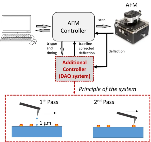
A commercial atomic force microscope (MFP3D, Asylum Research) was used for all AFM experiments. A novel double-pass method was implemented using an auxiliary data acquisition system to stabilize thermal drifts in the cantilever deflection (Figure 2.1). In this DC-stabilized imaging method, a double-pass scheme is used to first measure the baseline of cantilever deflection while the tip is 1 µm away from the surface, and this baseline is subtracted during topography acquisition. Using cantilevers with spring constants in the 0.02 N/m range, stable imaging can be achieved with force set points of 100 pN over prolonged durations. Force maps were taken at a resolution of 32 x 32 in 2 x 2 µm areas using a force-distance of 1 µm and scan rate of 2 Hz. Time-lapse images of nanofiber formation were also taken in 5 x 5 µm areas at a scan rate of 5 Hz, with each image being acquired in roughly 1 min.
28
Similarly, disassembly and self-healing images were measured in 1 x 1 µm areas and at a scan rate of 1.95 Hz, with each image being acquired in roughly 4 min. In order to analyze the force-distance measurements, custom programs (Matlab and IGOR Pro Software) was used to process the obtained data. All images were acquired at a resolution of 512 x 256 points and lines, respectively.
Figure 2. 1 Schematic description of the baseline-stabilized contact mode imaging system. An additional controller measures and subtracts the baseline using a double-pass scheme. Principle of baseline stabilized contact mode imaging. The tip is retracted from the surface and the deflection signal is measured and stored during the first pass,
AFM
Controller
deflection scan trigger and timingAdditional
Controller
(DAQ system)
baseline corrected deflectionAFM
1 µm
1
stPass
2
ndPass
29
while the measured baseline is subtracted from the deflection signal and temperature and instrumental drifts are eliminated in the second pass. This double-pass imaging scheme allows stable imaging with sub nN forces over extended periods of time.
2.3 RESULT AND DISCUSSION
2.3.1 Supramolecular Polymerization of Peptide Amphiphiles in Solution
Two oppositely charged PA molecules (E3Pa and K3PA) were designed (Figure 2.2)
and synthesized using the Fmoc solid phase peptide synthesis method.[73] The PA molecules used in this study are composed of a hydrophobic alkyl tail that is conjugated to a β-sheet forming pattern (-VVAG-) and either positively- or negatively-charged amino acid residues (-EEE or -KKK). This configuration triggers the co-assembly of PA molecules into cylindrical micellar structures through noncovalent interactions (i.e. electrostatic interactions, hydrogen bonding and hydrophobic interactions) in aqueous environment. The morphological properties of co-assembled PA nanofibers were observed by scanning electron microscopy (SEM) and transmission electron microscopy (TEM) (Figure 2.5). Circular dichroism (CD) spectroscopy was used to investigate the secondary structures of E3PA, K3PA and
mixed E3PA/K3PA molecules (Figure 2.6). CD spectra of the E3PA/K3PA mixture
revealed positive and negative signals at around 200 and 220 nm, respectively, corresponding to a twisted β-sheet conformation, while unmixed PA molecules showed negative peaks at ca. 195 nm, which is consistent with the random coil structure.[74,75] To investigate the differences in the aggregation behavior of mixed and unmixed E3PA and K3PA, critical aggregation concentrations of individual PA
molecules and their mixture were determined using a Nile Red assay (Figure 2.7). For E3PA and K3PA, micelle formation was only observed at a concentration of ~100 µM
30
and ~200 µM, respectively, while the co-assembled E3PA/K3PA system could form
micelles at a concentration of ~4 µM. The PA concentration (E3PA/K3PA) used for
AFM experiments was above the experimental critical aggregation concentration.
.
Figure 2. 2 Chemical structure of positively charged K3PA Lauryl-VVAGKKK-Am
31
Figure 2. 3 Liquid chromatogram of positively charged Lauryl-VVAGKKK-Am and mass spectrum of corresponding peptide molecule. Mass data [M+H]+ (calculated) = 910.26, [M+H]+(observed) = 910.69, (observed [M+2H]+2/2 = 455.83, [M+3H]+3/3 = 304.22).
32
Figure 2. 4 Liquid chromatogram of negatively charged Lauryl-VVAGEEE-OH and mass spectrum of corresponding peptide molecule. Mass data [M-H]- (calculated) = 914.06, [M-H]-(observed) = 912.50, (observed [M-2H]-2/2 = 455.75, [M-3H]-3/3 = 304.49).
33
Figure 2. 5 Representative SEM (left) and TEM (right) images of co-assembled K3PA
and E3PA molecules to show PA nanofiber networks and individual nanofibers.
Figure 2. 6 Secondary structure analysis of K3PA, E3PA and mixed E3PA/K3PA
molecules through circular dichroism.
34
Figure 2. 7 Nile Red assay of E3PA, K3PA, and E3PA/K3PA showing critical micelle
concentration. The maximum emission wavelength of PAs decreases as their concentration increases.
2.3.2 Co-Assembly of Oppositely Charged Peptide Amphiphile Nanofibers The mechanism of nanofiber formation by oppositely-charged PA nanostructures in aqueous environment was investigated in real-time using time-lapsed imaging on a mica surface. Frames representing nanofiber growth, measured over 10 minutes at a scanning rate of 1 frame per minute, are shown in Figure 2.8. We initially observed smaller aggregates[30] that formed dynamically on the surface, which subsequently
acted as nucleation points and eventually facilitated the development of mature nanofibers. The average growth rate of the nanofibers over time is shown in Figure 2.9 and was calculated based on the average growth of ten fibers traced from each image in Figure 2.8. The average elongation for each frame ranges from 60 to 140 nm min-1.
35
Growth of nanofibers continued until the surface was covered in a static nanofiber network (Figure 2.10, Supporting Video 1). Detailed investigation suggests that nanofiber growth occurs through “advancing fronts” at either end of each nanofiber, and that branching growth, potentially facilitated by defects on nanofiber surfaces, is more prominent during earlier stages of nanofiber formation. Nanofibers were incapable of extending over one another, and following contact between the advancing front of one nanofiber and the body of another, the elongation process either stopped or continued in parallel with the encountered fiber (Figure 2.10). Bundles formed by fiber-fiber contacts, rather than branching, therefore appears to drive the maturation of the nanofiber structure.
It is also likely that the negatively charged mica surface assists in fiber extension through electrostatic interactions with the positively-charged lysine residue of K3PA,
which prevents the developing fiber from leaving the surface and extending over another fiber. Since the surface of the muscovite mica is composed of negatively charged atomic layers, individual PA molecules (K3PA and E3PA) were also observed
on the mica surface in the same condition so that the affinity of ionic charge onto nanofiber formation through electrostatic interactions was determined. Positively charged K3PA molecules formed nanofibers significantly faster than the mixture of
oppositely charged E3PA/K3PA system on the surface, while the negatively charged
E3PA molecules did not show any fiber formation on the negatively charged surface
within nearly 3 hours. As such, time-lapsed images of K3PA molecules could be taken
for around maximum 1hour, whereas E3PA/K3PA system was managed to scan more
than 2.5 hours and the observation of nucleation and growth mechanism of nanofibers was in highly controlled manner.
36
Figure 2. 8 Representative deflection AFM images showing the nucleation and growth of co-assembled E3PA/K3PA nanofibers, measured
under time-lapse imaging over a 10 min period (in total 160 images were acquired). Time-lapse frames were measured at a scan rate of 1 frame per minute.
37
Figure 2. 9 Fiber elongation rate, as derived from each frame of the ten-minute image series.
In addition, the movement of the AFM tip can also modulate fiber formation by attracting peptide monomers through electrostatic interactions, physically dragging small assemblies over the surface, or creating disruptions in existing nanofibers that can serve as extension points for subsequent growth phases. Indeed, areas that were imaged extensively were observed to exhibit much denser nanofiber networks than the surrounding regions (Figure 2.13), and other studies have previously shown that the AFM tip can be used to pattern self-assembled peptide fiber structures.[31,33]
38
200 nm
1 µm
Figure 2. 10 PA nanofibers nucleated and grown in situ. (within 2.5 hours). Representation of the formation mechanism of a net-like fiber network. When a fiber encounters with another, it ceases its elongation and cannot extend further (black arrows).
39
Figure 2. 11 Representative deflection 10 minutes intermittent AFM images of K3PA molecules on the mica surface showing rapidly bundle
formation due to the electrostatic attraction between negatively charged mica layers and positively charged PAs
Figure 2. 12 Representative deflection AFM images of negatively charged E3PA molecules that unabled to self-assemble on
negatively-charged mica surface due to electrostatic repulsion within 3 hours.
0 min 10 min 20 min 40 min 60 min
1 µm
40
Figure 2. 13 Observation of affinity of AFM tip movements onto nanofiber formation throughout time-lapse imaging After 1 hour
41
A histogram of nanofiber diameters was also produced using Hough transform analysis, and the average nanofiber diameter was found to be ca. 5 nm (Figure 2.14), which is slightly lower than what is found in TEM analysis (ca. 8 nm). This diameter difference can be attributed to the sample preparation technique, as staining and drying is needed for TEM imaging, while nanofibers are directly scanned in solution for AFM measurements. As the latter condition is more representative of the “native” structure of the nanofibers, conical nanofibers with diameters of 4.5 nm (Figure 2.14) were used as the starting structure in EM simulations to maintain a diameter consistent with AFM observations.
42
Figure 2. 14 a) General appearance of a mature PA nanofiber network. Scale bar: 1 µm b) Histogram of nanofiber thickness showing that the average fiber thickness is ca. 5 nm and a conical fiber model with diameter of 4.5 nm used in energy minimization simulations (inset images).
0 nm 18 nm
43
2.3.3 Disruption of PA Nanofibers under Loading Force
A DC-stabilized double-pass scanning method was used for contact mode imaging. Briefly, a custom-designed Matlab algorithm was used to keep a constant difference (e.g. 0.2 V) between the measured value of deflection and the deflection set point, stabilizing the pressing force of the AFM tip during time-lapse imaging (Figure 2.1). The force exerted by the AFM tip can be controlled precisely through this DC-stabilized system, allowing the investigation of fiber disruption under varying pressure. Nanofiber deformation could be directly induced by gradually increasing the tip-mediated force applied to the fibers. Deformation was particularly evident at forces above 1 nN, which significantly lowered the average diameter of individual peptide fibers (Figure 2.15a), Supporting Video 2). Changes in the height and width profiles of a single nanofiber, shown with white arrow in Figure 2.15a, in response to increasing tip forces are shown in Figure 2.15b. Nanofiber breakage under tip-mediated forces was also investigated through the analysis of force-displacement data. Under an applied force of 2 nN, mica surfaces were found to exhibit linear force-displacement curves, while the disruption in peptide nanofiber integrity could be observed through a small “jump” in displacement during tip approach, during which the fiber presumably is damaged or pushed out from under the tip surface (Figure 2.19a shows the force-displacement analysis for a single nanofiber). Comparisons of force-displacement curves of multiple nanofibers, as well as the adhesion map associated with Figure 2.18a can be seen in Figure 2.18b. Displacement derivative analysis suggests that fiber breakage occurs at around 0.7 nN (Figure 2.19b), which is slightly lower than our experimental observations (1 nN).
44
Young’s modulus values of individual peptide nanofibers were also measured to determine the mechanical stability of the self-assembled networks. A total of 130 force curves were analyzed from three force maps, and the mean Young’s modulus of the peptide nanofibers was found to be ca. 33 MPa, as calculated with the JKR model (Figure 2.16 (inset)). However, the elasticity histogram associated with the nanofibers exhibited a broad distribution, which may suggest that more developed (or “mature”) fibers exhibit higher Young’s moduli than single, non-bundled strands. The distribution of adhesion forces was also calculated from 1024 data points and the mean adhesion force value was found to be ca. 1 nN for the peptide nanofibers on mica (Figure 2.17).
45
Figure 2. 15 a) Representative deflection AFM images of fiber deformation in response to increasing tip forces. b) Height and width profile of a single nanofiber (shown with white arrow) undergoing tip-mediated disruption, calculated using five regions across the length of fiber. Scale bar: 100 nm.
0.2 nN 0.4 nN 0.6 nN 1 nN 1.2 nN 1.4 nN 0 .2 0 .4 0 .6 1 1 .2 1 .4 2 .0 2 .5 3 .0 3 .5 4 .0 4 .5 F o r c e ( n N ) H e ig th ( n m ) 0 .2 0 .4 0 .6 1 1 .2 1 .4 2 5 3 0 3 5 4 0 4 5 F o r c e ( n N ) W id th ( n m )
a
b
46
Figure 2. 16 Representative force-curve measurement of co-assembled E3PA/K3PA nanofibers fitted by JKR model with Igor Pro
(AFM) software to calculate their average Young’s moduli. Inset image shows the histogram of the Young’s moduli of PA nanofibers which was found as 33 MPa on average.
Indentation (nm
)
Fo
rce
(n
N
)
0 2 0 4 0 6 0 8 0 1 0 0 1 2 0 0 5 1 0 1 5 2 0 2 5 Y o u n g 's m o d u lu s ( M P a ) F r e q u e n c yE = 58.65 MPa
E
mean= 33 MPa
Approach
Retraction
fit
47
Figure 2. 17 AFM height image, adhesion force mapping and histogram of adhesion force of co-assembled E3PA/K3PA nanofibers on
mica surface, respectively
Height image
Adhesion map
0 .0 0 .2 0 .4 0 .6 0 .8 1 .0 1 .2 1 .4 0 1 0 0 2 0 0 3 0 0 A d h e s i o n ( n N ) F r e q u e n c y
F
adh= 1 nN
48
Figure 2. 18 a) Representative peptide nanofibers image used for displacement analysis of fiber breakage. b) Selection of force-distance curves of mica and E3PA/K3PA fibers, showing collapse events in the latter.
49
Figure 2. 19 a) Differential response of mica and a peptide nanofiber against tip-induced forces. b) Displacement derivative analysis showing that fiber breakage occurs around 0.7 nN of force.
E3PA/K3PA
Mica