18
th
INTERNATIONAL CONFERENCE
ON
MACHINE DESIGN AND
PRODUCTION
Editorial Board
S. Engin KILIÇ Bahram LOTFISADIGHumtik 2018
3-6 July 2018
ESKİŞEHİR- TURKEY
MATIMAREN
DEPARTMENT OF MECHANICAL ENGINEERING MIDDLE EAST TECHNICAL UNIVERSITY ANKARA-TURKEY
All rights of this book are reserved by the Middle East Technical University.
None of the papers printed in this book may be reproduced without the prior permission, in writing, from the Author(s) of the paper(s) and the editors of the book. The papers can however be cited by giving the source.
This book can be obtained from the following addresses:
UMTIK
Mechanical Engineering Department Middle East Technical University 06800 Ankara- Turkey
Manufacturing Engineering Department ATILIM University
06830 Ankara- Turkey
Cover Print: METU- Ankara
Printing and Binding: METU- Ankara
Printed by: Dereağzı Fotokopi
Organizing Committee
Metin AKKÖK (METU, Dept. of Mechanical Eng.) [email protected] S. Engin KILIÇ (Atılım, Dept. of Manufacturing Eng.) [email protected]
Abdülkadir ERDEN (Beytepe Academi) [email protected] E. İlhan KONUKSEVEN (METU, Dept. of Mechanical Eng.) [email protected]
Cemal ÇAKIR” (Uludağ, Dept. of Mechanical Eng.) [email protected] Ulvi ŞEKER (Gazi, Dept. of Mechanical Eng.) [email protected] Ali ORAL (Balıkesiri, Dept. of Mechanical Eng.) [email protected] Besim BARANOĞLU (Atılım, Dept. of Manufacturing Eng.) [email protected] Bahram LOTFISADIGH (Atılım, Dept. of Manufacturing Eng.) [email protected] Nuran AY (Anadolu, Dept. of Mechanical Eng.) [email protected]
Evren YASA (E.Osmangazi, Dept. of Mechanical Eng.) [email protected]
Contact: [email protected] Tel: +90 312 586 8888
International Program Committee
Memiş ACAR UNITED KINGDOM Serpil ACAR UNITED KINGDOM M. Oktay ALNIAK TURKEY
Ahmet T. ALPAS CANADA Yusuf ALTINTAŞ CANADA Carla ANFLOR BRAZIL Ömer ANLAĞAN TURKEY
Stuart BARNES UNITED KINGDOM Erhan BUDAK TURKEY
Fuh-Kuo CHEN TAIWAN R.O.C. Jiun CHEN TAIWAN R.O.C. Tsung Chia CHEN TAIWAN R.O.C. Hugi CHRISTOPH SWITZERLAND Octavian CIOBANU ROMANIA Can ÇOĞUN TURKEY Samad DADVANDIPOUR HUNGARY Saied DARWISH SAUDI ARABIA László DUDÁS HUNGARY Bülent EKMEKÇİ TURKEY Ferenc ERDELYI HUNGARY Kaan ERKORKMAZ CANADA Emmanuel O. EZUGWU NIGERIA Tahir FIDAN TURKEY Necdet GEREN TURKEY Yiğit KARPAT TURKEY A. Sami KAZI FINLAND Adnan I. O. Zaid KILANI JORDAN Z. Murat KILIC CANADA Ismail LAZOGLU TURKEY Božidar KRIŽAN CROATIA Yangmin LI MACAU Ming-Chyuan LU TAIWAN R.O.C. Tzuo Liang LUO TAIWAN R.O.C. Yoshiyuki MATSUOKA JAPAN Christoph MEIER SWITZERLAND Toshimichi MORIWAKI JAPAN Jokin MUNOA SPAIN Samad NADIMI BAVIL OLIAI TURKEY Karoly NEHEZ HUNGARY Tuğrul ÖZEL USA Fahrettin ÖZTÜRK TURKEY Can SAYGIN USA Eiji SHAMATO JAPAN Arzu (GÖNENÇ) SORGUÇ TURKEY Uğur ŞİMŞİR TURKEY Tibor TOTH HUNGARY Ali ÜNÜVAR TURKEY Hakkı Özgür ÜNVER TURKEY Mustafa UYSAL TURKEY Ivica VEZA CROTIA
Min WAN P.R.C.
Bülent YILMAZ TURKEY Michael ZAEH GERMANY
The 18th International Conference on Machine Design and Production
July 3 – July 6 2018, Eskişehir, Turkey
DESIGN AND FABRICATION OF LARGE-SIZE FFF 3D PRINTER
Gokberk SERİN, [email protected] TOBB University of Economics and Technology, 06560,Ankara, Turkey.
Hakki Ozgur UNVER, [email protected] TOBB University of Economics and Technology, 06560,Ankara, Turkey.
Recep Muhammet GORGULUARSLAN, [email protected], TOBB University of Economics and Technology, 06560,Ankara, Turkey.
Sadik Sinan KOSUMCU, [email protected], Form Makina A.Ş., 34775, İstanbul, Turkey.
ABSTRACT
Additive manufacturing, also known as “3D printing” keeps diffusing into many industries with a rapid pace. The greatest advantage of 3D printers is that it allows the designers to produce a prototype in a very short time that can be tested and quickly remodeled if necessary. This significantly reduces the required time to advance from the design phase to the final product. Another great advantage is manufacturing components which have very complex and precise forms through this technique. It is also possible to speed the process of manufacturing of complex parts which can be produced in a long time with conventional methods. In this paper, the design and fabrication of a large size FFF 3D delta printer, also the challenges encountered during the fabrication are presented.
Keywords: 3D Delta Printer, Fused Filament Fabrication (FFF), Thermoplastic Polymer Materials
1. INTRODUCTION
Three-dimensional (3D) printing is a new technology which was first invented in 1984 by Chuck Hull. 3D printing technologies have been developed rapidly over the last 30 years and provide practical solutions for many application areas. It allows for manufacturing any part regardless of the complexity with many different materials. 3D printer is a machine that transforms 3D computer data (i.e. an STL.file) into real solid objects that you can hold with your hands by
The 18th International Conference on Machine Design and Production
July 3 – July 6 2018, Eskişehir, Turkey
building the part layer by layer. This technology is capable of producing geometries that cannot be manufactured by conventional manufacturing methods. It also has other advantages such as cost-effective prototype production, which is also known as rapid prototyping, quicker launch to market, and ability to print customized products with very little waste [1-3].
The first application of the 3D printing technologies dates back to 1984, but in the past 20 years, this method has not received much attention apart from the rapid prototyping area. The Reprap (replicating rapid prototyper) project, which was started in 2006, has reached much wider masses. The increase of the compound annual growth rate of the 3D printing technology is shown in Figure 1. The compound annual growth rate (CAGR) from 2016 to 2024 is estimated to be 21.7% and the global market volume of the 3d printer estimated by Variant Market Research is expected to reach $ 3.628 billion [4]. Thanks to the Reprap project, many ordinary users, hobbyists and people in need to produce any parts themselves in their home or office can fabricate a 3D printer. Even about three years after the start of the project, many companies have been able to spread the technology to a wider user mass by taking advantage of the Reprap project to produce relatively low-cost and sell open source 3D printers [1]. According to Berman’s study, the waste material in 3-D printing technology is reduced by 40% in comparison to machining/subtractive technologies. Furthermore, 95% - 98% of waste material can be recycled in 3-D Printing. In addition, the subtractive technologies such as machining can remove as much as 96% of the raw material when creating a product. In terms of the cost per part in mass production, the 3D printing technology doesn’t have much advantage than injection molding and machining as yet [5].
Figure 1. Global Automotive 3D Printing Market Size and Forecast, 2015 - 2024 ($ Million) [4] 3D printers can be built using many different technologies. Nowadays, the most popular method is material extrusion method which is a stacking technology and also known as Fused Filament Fabrication (FFF). Thermoplastic polymer materials (PLA, ABS) which can be formed by heat are used in this method. The heated material (filament) is extruded and the desired parts are produced with the principle stacking layers together in the FFF technology as shown
The 18th International Conference on Machine Design and Production
July 3 – July 6 2018, Eskişehir, Turkey
in Figure 2. The parts which have high strength are achieved with this technology, if the material of filament is plastic. In other respects, in FFF technology, it is quite troublesome to produce stalactite suspended structures in the air. In such situations, support structures are used to carry the bulk of the mass on the stalactite suspended structures [2-6].
Figure 2. The operation method of the material extrusion process [6]
Acrylonitrile butadiene styrene (ABS) is a light and hard polymer widely used in products produced by molding. Its chemical formula is (C8H8.C4H6.C3H3N)n. Pipes, automotive parts, protective helmets and toys (e.g. Lego) are just a few of its usage areas [4]. Poly (lactic acid) (PLA), one of the biodegradable polymers, is used in the field of medicine, wrapping, packaging and textile very effectively. There are various differences between PLA and ABS as shown in Table 1. The most important difference is that the filament from PLA is abundant, natural and renewable resource, nevertheless, ABS is petroleum based plastic. Thus, PLA is more harmless than ABS for human health. Second difference is that, it is necessary to heat the print bed to higher degrees when using ABS as a filament material since the ABS is more influenced by the temperature difference. Because of the lower printing temperature, when the PLA is properly cooled down, it is possible to print more sharp edges and features compared to ABS [4, 5]. The other difference is that PLA is generally used if the form is more critical than the function, because PLA is less stretchy than ABS. However, ABS has higher flexural strength and better elongation properties [6-9].
Table1. Comparison of PLA and ABS properties Type of filament Resource Mechanical behavior Print bed temperature Printing
temperature Common Products PLA Organic Brittle 20-60°C
(optional)
180-230°C Lego, automotive parts, electronic housing etc.
ABS
Petroleum-
based Ductile
80-110°C
The 18th International Conference on Machine Design and Production
July 3 – July 6 2018, Eskişehir, Turkey
1.1 Types of FFF 3D Printers
Delta and cartesian printers are the most popular FFF 3D printers on the market. However, there are important differences between the two. For instance, the delta 3D printer usually has a circular print bed that is immovable, because its natural shape is circle. On the other hand, the cartesian printer has a rectangular print bed. The volume of the 3D printer and its bottom surface area (print bed) need to be increased when printing large parts, thus the moving parts of the cartesian printer heavier than the moving parts of delta printer. This situation influences sensitivity of positioning. At the same time, the fact that each element can move only in one direction for the cartesian printer affects the sensitivity of positioning. In the delta printer, the nozzle head can move in any direction quickly. Therefore, on the contrary to the cartesian printer, the delta printer is preferred to print large and big parts [10-12].
Moreover, the nozzle head of the cartesian printer can move only in X and Y axes. The z axis represents the direction in which the surface area can move. Unlike the cartesian printer, the delta printer moves the nozzle in X, Y, Z axes as shown in Figure 3. Hence, calibration of the delta 3D printers becomes more troublesome [11, 13].
In a study, in vase mode, print speeds of the delta and cartesian 3D printer have been compared. Cartesian printers achieve print speeds of up to 200 mm / sec, while delta printers have a speed of 350 mm / sec. The biggest reason of this situation is that the positioning speed and sensitivity of the nozzle in the delta printer is better than the cartesian printer [13].
Figure 3. Cartesian and delta printer [11]
Laplume et al. (2016) have studied on differences between MOST Prusa RepRap (Cartesian Printer) and MOST Delta RepRap Printers. Their study shows capital cost of the delta printer (400$) is lower than the cartesian printer (575$) as shown in Table 2. Also, the energy consumption to warm up the printer and for movement of axes is lower in the delta printer [12].
The 18th International Conference on Machine Design and Production
July 3 – July 6 2018, Eskişehir, Turkey
Table 2. Comparison of the delta printer and the cartesian printer [10-13]
Type of Printer
Capital cost ($)
Weight Print speed Sensitivity of positioning
The nozzle movement axes
Calibration
Delta Printer 400 Light High High X,Y,Z Difficult Cartesian Printer 575 Heavy Medium Medium X,Y Easy
In this study, a delta type FFF printer is developed due to its above-mentioned advantages over the cartesian type printers. Furthermore, it is aimed to develop a large-scale printer to be able to print large parts with high accuracy, which differs from the existing delta type FFF printers in the literature. For this purpose, the product architecture of a delta type FFF printer is investigated first and details are provided in Section 2. Then, the development process of the large-scale printer is described in Section 3. An accuracy study is carried out and many challenging parts are produced and the results are given in Section 4. The challenges during the development process and the solutions suggested are explained in Section 5 and the conclusions are given in Section 6.
2. PRODUCT ARCHITECTURE
In the production process of a part using a delta type FFF printer, some steps should be followed as shown in Figure 4. First, a computer-aided design (CAD) file of the 3D model is created in “STL” file format. Afterwards, this file is sent to the slicing software which slices the 3D model to the thin layers and creates g-codes for these layers. These g-codes are sent to the controller (Arduino Mega). A Ramps 1.4 board is used together with Arduino which controls to electronic components such as servo motors. A few steps should be taken while printing a product from 3D printer.
The 18th International Conference on Machine Design and Production
July 3 – July 6 2018, Eskişehir, Turkey
Step I: Designing the part to be printed
The CAD file formats such as part file (.prt), step file (.step) and Catia model file (.model) can be created using 3D modeling program such as Autocad, Solidworks, Catia, Simens NX etc. Then, the CAD file is converted to an STL file, which is the format that is sent to the slicer software tools such as Cura, Simplify 3D or 3D Slicer.
Step II: Generating G-code
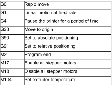
G-code is created to determine the printing process of a product using a 3D printer. The generated G-code includes the type of movement of the nozzle head, setting units toinches/millimeters, setting absolute/relative positioning etc.. Also, there are M commands to indicate program end, enable/disable all stepper motors, turn off bed, turn off extruder etc..The definitions of some important G and M commands are listed in Table 3.
Table 3. Common G and M codes for 3D printer G0 Rapid move
G1 Linear motion at feed rate
G4 Pause the printer for a period of time G28 Move to origin
G90 Set to absolute positioning G91 Set to relative positioning M2 Program end
M17 Enable all stepper motors M18 Disable all stepper motors M104 Set extruder temperature
Step III: Motor control
The operation of a 3D printer needs motors with low torque and high accuracy, so the best motor to do this function is stepper motor. It is an electromagnetic device that converts digital pulses into mechanical shaft rotation. Advantages of step motors are low cost, high reliability, and high torque at low print speeds. They are also a special type of the synchronous motors which are designed to rotate a specific number of degrees for every electric pulse received by its control unit. In a delta type 3D printer, four stepper motors are needed to do the specific function, three of them are used for moving in X, Y, Z direction of the printer head, the 4th one is needed to move the filament.
The 18th International Conference on Machine Design and Production
July 3 – July 6 2018, Eskişehir, Turkey
Step IV. Printing
The final step is to print the product using ABS or PLA. The dimensions of the 3D printer must be introduced to slicer software tools before printing product. Also, process parameters determining to quality of product, printing time and density of the product should be regulated. Thereafter, the product in desired size can be printed by the delta printer.
3. DEVELOPMENT OF THE DELTA TYPE FFF 3D PRINTER 3.1. Mechanical design of the developed FFF printer
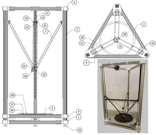
3D printers have several main design requirements such as mechanical design, kinematic analysis, and control system. In order to run the delta type 3D printer and produce the product, mechanical design must be done before creating the kinematic analysis and control system of the system. Therefore, the structural parts that create the basic shape of the printer and carry moving parts must be designed. These are principally aluminum profiles, angle brackets, linear rail system, carriage, carbon fiber rods and effector as shown in Figure 5. The definitions of the numbered components in Figure 5 are given in Table 4.
Figure 5. 3D CAD model of delta 3D printer
The 18th International Conference on Machine Design and Production
July 3 – July 6 2018, Eskişehir, Turkey
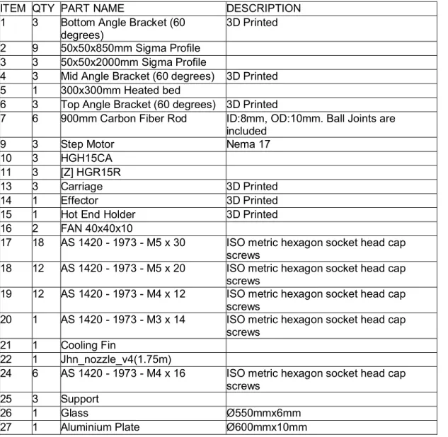
and carry the rail system. Therefore, in the development process of the delta type printer, first, the aluminum profiles were designed by considering the main dimensions of the printer. There are three different type of brackets used in this system, which enable the connections of the aluminum profiles, such as top, middle and bottom brackets, shown by numbers 6, 4, and 1 in Figure 5, respectively. These brackets provide enough support and rigidity. They are designed on a commercial CAD software Solidworks by accounting for the geometry of the aluminum profiles. These customized angle bracket designs are manufactured using PLA material in a cartesian type FFF printer. Also, linear rail system consists of stepper motor, timing belt, rods, effector and carriage, shown by numbers 7, 9, 13, and 14 in Figure 5, respectively. The carriage is used to carry rods from carbon fiber and PLA-made effectors. This rail system is moved by three different stepper motor and timing belt. It is connected to the aluminum profiles with hammer nuts. Detailed descriptions of the parts shown in Figure 5 are mentioned in Table 4.
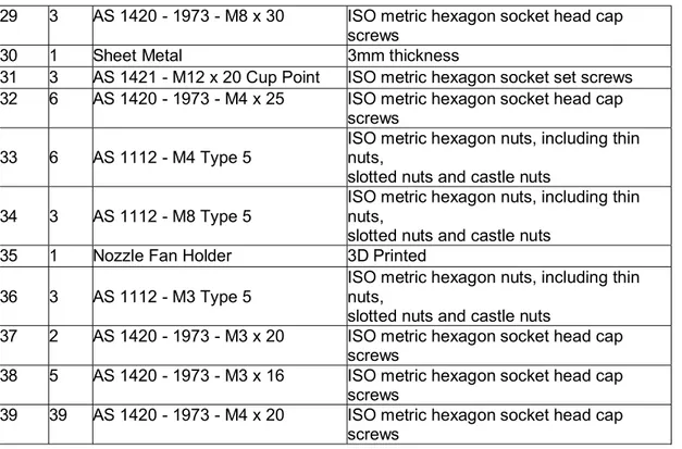
Table 4. Bill of materials of delta printer fabricated ITEM QTY PART NAME DESCRIPTION 1 3 Bottom Angle Bracket (60
degrees)
3D Printed 2 9 50x50x850mm Sigma Profile
3 3 50x50x2000mm Sigma Profile
4 3 Mid Angle Bracket (60 degrees) 3D Printed 5 1 300x300mm Heated bed
6 3 Top Angle Bracket (60 degrees) 3D Printed
7 6 900mm Carbon Fiber Rod ID:8mm, OD:10mm. Ball Joints are included
9 3 Step Motor Nema 17 10 3 HGH15CA
11 3 [Z] HGR15R
13 3 Carriage 3D Printed 14 1 Effector 3D Printed 15 1 Hot End Holder 3D Printed 16 2 FAN 40x40x10
17 18 AS 1420 - 1973 - M5 x 30 ISO metric hexagon socket head cap screws
18 12 AS 1420 - 1973 - M5 x 20 ISO metric hexagon socket head cap screws
19 12 AS 1420 - 1973 - M4 x 12 ISO metric hexagon socket head cap screws
20 1 AS 1420 - 1973 - M3 x 14 ISO metric hexagon socket head cap screws
21 1 Cooling Fin
22 1 Jhn_nozzle_v4(1.75m)
24 6 AS 1420 - 1973 - M4 x 16 ISO metric hexagon socket head cap screws
25 3 Support
26 1 Glass Ø550mmx6mm 27 1 Aluminium Plate Ø600mmx10mm
The 18th International Conference on Machine Design and Production
July 3 – July 6 2018, Eskişehir, Turkey
29 3 AS 1420 - 1973 - M8 x 30 ISO metric hexagon socket head cap screws
30 1 Sheet Metal 3mm thickness
31 3 AS 1421 - M12 x 20 Cup Point ISO metric hexagon socket set screws 32 6 AS 1420 - 1973 - M4 x 25 ISO metric hexagon socket head cap
screws 33 6 AS 1112 - M4 Type 5
ISO metric hexagon nuts, including thin nuts,
slotted nuts and castle nuts 34 3 AS 1112 - M8 Type 5
ISO metric hexagon nuts, including thin nuts,
slotted nuts and castle nuts 35 1 Nozzle Fan Holder 3D Printed
36 3 AS 1112 - M3 Type 5
ISO metric hexagon nuts, including thin nuts,
slotted nuts and castle nuts
37 2 AS 1420 - 1973 - M3 x 20 ISO metric hexagon socket head cap screws
38 5 AS 1420 - 1973 - M3 x 16 ISO metric hexagon socket head cap screws
39 39 AS 1420 - 1973 - M4 x 20 ISO metric hexagon socket head cap screws
3.2. Kinematic analysis of the developed FFF Printer
In a cartesian printer, the mechanism moves along the rails independently of each other in the x, y, and z directions. With a delta configuration, it's not that simple. Moving any of the three vertical carriages upward and downward causes the nozzle head to move simultaneously in x, y, and z. Therefore, it is necessary to calculate how each of three carriages will move in order to move the nozzle head to the right place [14].
Figure 6. a) Delta printer diagram, b) Positioning of the carriage and effector
The 18th International Conference on Machine Design and Production
July 3 – July 6 2018, Eskişehir, Turkey
and C. Each column has a carriage that can move up and down on the column. Each carriage has two parallel arms which connect to the effector platform. It is crucial that each of the parallel arms (rods) is the same length and the platform of the effector must be parallel to the print bed in order to print correctly. In accordance with this purpose, the distance between the junction of the each carriage with columns and effector platform must be the same. Thus, the nozzle head moves parallel to the print bed when designed in this way [15].
After the rods, carriages and platform of the effector are positioned correctly, the positions of the carriages must be calculated by kinematic analysis so that the nozzle head can move to the desired point on the print bed. It is shown in Equations (1), (2), and (3).
= + + − = + + − ( − ) − ( − ) = + + − − ( + ) − (0 − ) = + + − ( − ) − 2 + − (1) = + + − = + + − ( − ) − ( − ) = + + − ( 120° − ( + 120°)) − ( 120° − ( − 120°)) (2) = + + − = + + − ( − ) − − = + + − ( 240° − ( + 240°)) − ( 240° − ( − 240°)) (3)
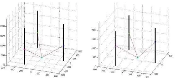
Equations (1), (2), and (3) are analyzed in MATLABTM to obtain final position of the nozzle head. For example, the nozzle head moves from (0, 0, 0) to (150, -150, 300) with 200 mm/s velocity and 2000 mm/s2 acceleration/deceleration. The Figure 7 shows the final position of the nozzle head.
The 18th International Conference on Machine Design and Production
July 3 – July 6 2018, Eskişehir, Turkey
Figure 7. Matlab graphs of the position of the nozzle head at a) (0, 0, 0) and b) (150, -150, 300)
3.3. Control system of the developed FFF Printer
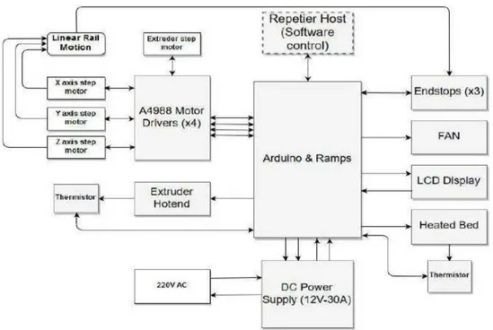
The diagram shown in Figure 8 points the detailed relationships between all electrical components such as Arduino Mega 2560, RAMPS 1.4 (RepRAP Arduino Mega Pololu Shield), A4988 Motor drivers (x4), 12v PSU, NEMA 17 step motors (x4), hot end and heatbed. The ATmega2560 (datasheet) is an Arduino based card. There are 54 digital I / O pins. 14 of them can be used as PWM output. PWM (pulse width modulation) is a way to control analog components using digital signals. Also, there are 16 analog inputs, 4 UART (serial port), 16 MHz crystal oscillator, USB connection, an adapter input, an ICSP output and a reset button. The system takes the power from main supply and a direct current power supply regulates this power to send it to the controller. After that Arduino sends digital, PWM and analog signals to Ramps board. Ramps board uses these signals and controls the current from the dc power supply. All electronic components use this current to work.
The 18th International Conference on Machine Design and Production
July 3 – July 6 2018, Eskişehir, Turkey
Figure 8. Electronic system diagram 3.4. Specifications of the developed delta type FFF printer
The developed 3D printer has a delta head and large build volume. Therefore, it has unique design compared to other 3D printers in the literature. The final specifications of the developed 3D printer are given in Table 5.
Table 5. Specifications of delta printer manufactured Technology Fused Filament Fabrication (FFF)
Control system Arduino based control system, open source control software Print head Single
Maximum speed (mm/s) 200
Printer dimensions (mm) 1050 X 950 X2050
Build volume (mm) 500 diameter X 750 height Nozzle temperature (°C) 280
Supported materials ABS, PLA, PLA+ Noise level (dB) 65
Weight (kg) 90 XY resolution (mm) 0.03 Z resolution (mm) 0.06
The 18th International Conference on Machine Design and Production
July 3 – July 6 2018, Eskişehir, Turkey
4. PRINTING RESULTS
Several parts have been printed in different sizes by the developed delta type FFF 3D printer. First, a dimensional deviation analysis has been performed on 20*20*20 mm cubes, which are placed in different positions on the print bed, as shown in Figure 9. It is observed that deviation values are between 1.1%-0.1% in X axis, 2.5%-0.75% in Y axis and 2%-0.4 in Z axis. Table 6 shows the results of the dimensional deviation occurred in X, Y, Z axes.
Figure 9. Cubes printed for dimensional deviation analysis Table 6.Dimensional deviation values in X, Y, Z axes
Zone Location Actual Dimensions
Dimensions of Printed Part Dimensional Deviation X- coordinat e (mm) Y- coordinate (mm) in X axis (mm) in Y axis (mm) in Z axis (mm) in X axis (mm) in Y axis (mm) in Z axis (mm) in X axis (%) in Y axis (%) in Z axis (%) 1 0 0 20 20 20 19,98 19,78 20,18 0,1 1,1 0,9 2 0 -220 20 20 20 19,98 20,15 20,08 0,1 0,75 0,4 3 0 220 20 20 20 19,86 19,62 20,14 0,7 1,9 0,7 4 -220 0 20 20 20 19,78 19,96 20,4 1,1 0,2 2 5 220 0 20 20 20 20,04 19,5 20,25 0,2 2,5 1,25 As can be seen from Table 6, the dimensional deviations of the printer parts compared to the actual dimensions are mostly less than 1.1%. In some cases (such as the Y axis deviation of
The 18th International Conference on Machine Design and Production
July 3 – July 6 2018, Eskişehir, Turkey
Zone 3, Y axis, and Y and Z axes of zone 5 those are less than 2.5%. These results show that the developed 3D printer can accurately print parts at any location of the 3D printer on XY plane.
Once the geometric deviation study has been completed, then various parts have been manufactured by the developed printer. First, small parts have been manufactured by the developed delta printer, then moved on to larger parts which can take up to 35 hours to print. The herringbone gear with an outer diameter of 70 mm and a thickness of 10 mm shown in Figure 10(a) has been printed in 3.5 hours using the nozzle with 0.4 mm radius. The spiral vase with a height of 300 mm in Figure 10(b) has been printed in 4.5 hours using the nozzle with 0.8 mm. It was printed in the vase mode at 200 mm/s print speed. The Eiffel tower with a height of 500 mm in Figure 10(c) has been printed in 26 hours using a nozzle with a radius of 0.8 mm. Although it has very small features, the developed printer was able to print those without any issues. The cylindrical hollow part shown in Figure 10(d) was printed in 36 hours using the nozzle with 0.4 mm radius. This part has a height of 650 mm which is used to test if the developed printer can print high parts in Z direction. This part is also designed using lattice structures with strut members having circular cross sections with a constant dimeter of 5 mm to have a lightweight design. It was shown by printing this part that the developed printer can manufacture large components with high complexity such as lattice structures with interconnected strut members.
The 18th International Conference on Machine Design and Production
July 3 – July 6 2018, Eskişehir, Turkey
5. CHALLENGES IN THE DEVELOPMENT OF THE PRINTER
Some challenges have been encountered while developing 3D delta printer. Vibration is the most important problems occurred during the printing. Vibration mostly occurs due to height of the printer. Some head movements can resonate the system and magnify the vibration. As a result of vibration, waviness can be seen at the printed layer. To overcome this problem, the printer has been made rigid as much as possible. Another problem encountered is that the power of the extrusion becomes insufficient. When the Teflon tube is too long, the buckling between extruder system and cold end of the extruded filament has been occurred and in this case, the movement of the filament in the Teflon tube becomes more difficult. To solve this problem, the extrusion motor has been relocated by making a design change. Length of the Teflon tube is shortened by moving the extrusion system closer to the effector. This reduces the additional buckling in the Teflon tube. Therefore, required force for pushing the filament inside of the tube is decreased. Also the position of the potentiometers are adjusted, torque of the stepper motors are increased by 20%. Thus, sufficient power could be provided for the extrusion.
Moreover, initially, a fixed printing surface has been designed but the printing surface was not horizontally placed. Since the printing surface was fixed, no changes could be made to adjust its leveling setting. For this reason, the printing surface caused an inconsistent first layer of the print, which lead to failures in printing in later stages of the process. To address this issue, the printing plate redesigned in a way that its leveling setting can be adjusted by rotating the set screws on it.
The last challenge encountered during this study was stringing issue when the nozzle moves from one part of the print to another. To overcome problem, the retraction speed between two printed areas and excessive hot end temperature must be increased.
6. CONCLUSION
In this study, a large-scale delta type FFF 3D printer is developed and components with various sizes and complexities are modeled and manufactured to show its efficacy. The results showed that the developed printer can manufacture large scale parts with high accuracy. Some issues have been encountered during the development process such as the insufficient power of the extrusion, uneven printing surface, and the stringing issue. These issues are solved by making additional modifications on the design of the printer. As a result, it was possible to print with a dimensional error below 2.5% after the mentioned problems have been solved.. The dimensional tolerance of the 3D printers in the literature is also below 4%, which show that the developed printer can achieve better tolerance values than the existing printers. Unlike the
The 18th International Conference on Machine Design and Production
July 3 – July 6 2018, Eskişehir, Turkey
existing FFF 3D printers in literature, the developed printer, namely, UB3D, have a larger print volume and can manufacture large scale parts with high accuracy.
ACKNOWLEDGEMENTS
The authors would like to express their deepest gratitude to the undergraduate students Batihan SENER, Dogukan TURAN, Mehmet Emin CAGIL and Uluc PINAR due to their efforts for realization of this work. Advanced Manufacturing Laboratory Technician, Kamil ARSLAN, is gratefully acknowledged. This study was supported by Form Makina A.Ş.
REFERENCES
1. Hao, L.J., (2014), “3D-Printing: the Future of Manufacturing”,
https://junhaolimtwc.wordpress.com/2014/03/19/individual-report-draft-2/, date accessed: 15.02.2018.
2. Roberson, D.A., Espalin, D., Wicker, R.B., (2013), “13D Printer Selection: A Decision- Making Evaluation and Ranking Model”, Virtual and Physical Prototyping, 8(3), 201-212. 3. Braankeri G.B., Duwel, J.E.P., Flohil, J.J., Tokaya, G.E., (2010), “Developing a Plastics Recycling Add-on for the RepRap 3D printer”.
4. Variant market research, (2016), “Automotive 3D Printing Market Overview”,
https://www.variantmarketresearch.com/press-release/global-automotive-3d-printing-market- is-estimated-to-reach-usd-3628-million-by-2024-says-variant-market-research,
date accessed: 22.02.2018.
5. Berman, B., (2012), “3D Printing: the New Industrial Revolution”, Business Horizons, 55(2), 155-162.
6. Santos, R., James, J., Chris, T:, Marshall, S., Maalouf, P., (2015), “Deltronic Solutions”, Senior Project, Cal Poly IME Department, America.
7. Rohringer, S., (2017), “PLA vs ABS: Filaments for 3D Printing Explained & Compared”, https://all3dp.com/pla-abs-3d-printer-filaments-compared/, date accessed: 01.03.2018. 8. Tymrak, B.M., Kreiger, M., Pearce, J.M., (2014), “Mechanical Properties of Components Fabricated with Open-Source 3-D Printers under Realistic Environmental Conditions”, Materials & Design, 58, 242-246.
9 .Ferreira, R.T:L., Amatte, I.C., Dutra, T.A:, Burger, D., (2017), “Experimental Characterization and Micrography of 3D Printed PLA and PLA Reinforced with Short Carbon
The 18th International Conference on Machine Design and Production
July 3 – July 6 2018, Eskişehir, Turkey
Fibers”, Composites Part B: Engineering, 124(1), 88-100.
10. Tractus 3D company report, (2018), “3D Printing Technology Delta versus Cartesian”, https://tractus3d.com/3d-printing-technology/#, date accessed: 05.03.2018.
11. Alex, M., (2017), “The 4 Types pf FFF/FDM 3D Printer Explained (Cartesian, Delta, Polar)”, https://www.3dnatives.com/en/four-types-fdm-3d-printers140620174/, accessed date: 11.03.2018.
12. Laplume, A., Anzalone, G.C., Pearce, J.M., (2016), “Open-Source, Self-Replicating 3-D Printer Factory for Small-Business Manufacturing”, The international Journal of Advanced Manufacturing Technology, 85(1-4), 633-642.
13. Plasticwrap3d, (2017), “3D Delta vs Cartesian High Speed Print Test”,
https://plasticwrap3d.wordpress.com/2017/04/12/3d-delta-vs-cartesian-high-speed-print-test/, accessed date: 13.03.2018.
14. Graves, S., (2018), “Johann C. Rocholl (Rostock) Style - Delta Robot Kinematics”, http://fab.cba.mit.edu/classes/863.15/section.CBA/people/Spielberg/Rostock_Delta_Kinemati cs_3.pdf, accessed date: 20.03.2018
15 Scary Maths- Tiny gadgets, (2017), “How to Convert from x,y,z Coordinates to Delta Robot Position”, http://robinsonia.com/wp/?p=161, accessed date: 21.03.2018
![Figure 1. Global Automotive 3D Printing Market Size and Forecast, 2015 - 2024 ($ Million) [4] 3D printers can be built using many different technologies](https://thumb-eu.123doks.com/thumbv2/9libnet/3748592.27932/5.918.176.745.678.882/figure-automotive-printing-forecast-million-printers-different-technologies.webp)
![Figure 2. The operation method of the material extrusion process [6]](https://thumb-eu.123doks.com/thumbv2/9libnet/3748592.27932/6.918.282.643.216.447/figure-operation-method-material-extrusion-process.webp)
![Figure 3. Cartesian and delta printer [11]](https://thumb-eu.123doks.com/thumbv2/9libnet/3748592.27932/7.918.245.683.660.877/figure-cartesian-and-delta-printer.webp)
![Table 2. Comparison of the delta printer and the cartesian printer [10-13]](https://thumb-eu.123doks.com/thumbv2/9libnet/3748592.27932/8.918.246.676.794.1033/table-comparison-delta-printer-cartesian-printer.webp)