1048
|
wileyonlinelibrary.com/journal/mrm Magn Reson Med. 2020;84:1048–1060.F U L L PA P E R
MR safety watchdog for active catheters: Wireless impedance
control with real-time feedback
Ali Caglar Özen
1,2,3|
Berk Silemek
4,5|
Thomas Lottner
1|
Ergin Atalar
4,6|
Michael Bock
11Department of Radiology, Medical Physics, Medical Center - University of Freiburg, Freiburg, Germany 2Faculty of Medicine, University of Freiburg, Freiburg, Germany
3German Consortium for Translational Cancer Research Partner Site Freiburg, German Cancer Research Center (DKFZ), Heidelberg, Germany 4National Magnetic Resonance Research Center (UMRAM), Bilkent University, Ankara, Turkey
5Physikalisch-Technische Bundesanstalt (PTB), Braunschweig and Berlin, Germany 6Department of Electrical and Electronics Engineering, Bilkent University, Ankara, Turkey
This is an open access article under the terms of the Creative Commons Attribution License, which permits use, distribution and reproduction in any medium, provided the original work is properly cited.
© 2020 The Authors. Magnetic Resonance in Medicine published by Wiley Periodicals, Inc. on behalf of International Society for Magnetic Resonance in Medicine
Correspondence
Ali Caglar Özen, Department of Radiology, Medical Physics, Medical Center– University of Freiburg, Killianstrasse 5a, 79106 Freiburg, Germany.
Email: [email protected]
Purpose: To dynamically minimize radiofrequency (RF)-induced heating of an
active catheter through an automatic change of the termination impedance.
Methods: A prototype wireless module was designed that modifies the input
imped-ance of an active catheter to keep the temperature rise during MRI below a threshold,
ΔTmax. The wireless module (MR safety watchdog; MRsWD) measures the local
temperature at the catheter tip using either a built-in thermistor or external data from a fiber-optical thermometer. It automatically changes the catheter input impedance
until the temperature rise during MRI is minimized. If ΔTmax is exceeded, RF
trans-mission is blocked by a feedback system.
Results: The thermistor and fiber-optical thermometer provided consistent
tempera-ture data in a phantom experiment. During MRI, the MRsWD was able to reduce the maximum temperature rise by 25% when operated in real-time feedback mode.
Conclusion: This study demonstrates the technical feasibility of an MRsWD as an
alternative or complementary approach to reduce RF-induced heating of active inter-ventional devices. The automatic MRsWD can reduce heating using direct tempera-ture measurements at the tip of the catheter. Given that temperatempera-ture measurements are intrinsically slow, for a clinical implementation, a faster feedback parameter would be required such as the RF currents along the catheter or scattered electric fields at the tip.
K E Y W O R D S
active catheter, active implantable medical devices, bluetooth low energy, interventional MRI, MR safety, radio frequency induced heating
1
|
INTRODUCTION
MRI is increasingly used to control minimally invasive
inter-ventions1-10—for example, breast or prostate biopsies are
al-ready carried out routinely under MRI guidance. Endovascular interventions, however, are still mainly performed using x-ray fluoroscopy or computed tomography, given that these modali-ties provide a high image frame rate, a good instrument visibility as well as an excellent access to the patient. The main disadvan-tage of these x-ray-based technologies is the usage of ionizing radiation that leads to poor soft tissue contrast and a potentially dangerous radiation dose for both the patient and physician. At present, however, x-rays are indispensable because medical instruments, such as guidewires, catheters, or stents, are often not suitable for use in MRI. In particular, the electric (E) field component of the radiofrequency (RF) fields in MRI can inter-act with the elongated electrically conducting structures of the instruments, such that heating can occur in sensitive parts of the
body.11-31 Unwanted RF heating is mainly observed at the tip
of an instrument19—here, the strong local electric fields
gener-ate currents in the adjacent tissue, which lead to tissue heating. This heating can be particularly strong when the length of the
implant is comparable to the RF wavelength in tissue.18
Active catheters have been designed for MRI-guided inter-ventional operations, such as tissue ablation or intravascular stent placement. Active devices with small tracking coils at the tip offer advantages over other tracking techniques, given that the active tracking coil can be identified and localized
unambig-uously.1-4 So far, studies on MR safety of active catheters have
been limited to experimental setups.32-34 Current MR safety
standards assess RF heating during hypothetical worst-case
positioning and RF field configurations,35 but these conditions
can be impractical, and they may overestimate the heating risk. Previous studies have also confirmed that RF-induced heating of elongated devices highly depends on the insertion length, dielectric properties of the medium, and the incident field.18,36-42
During an intervention, all these parameters can be subject to rapid changes, which may cause an unexpected temperature rise around the tip. In a previous work,43 finite difference time-
domain (FDTD) simulations revealed that the ratio of the peak spatial specific absorption rate (SAR) to the whole-body SAR can increase by a factor of up to 800 when the anatomical fea-tures change. Therefore, a more realistic safety assessment is needed that includes real-time monitoring of local tissue heat-ing. For example, recently, a temperature sensor implant that mimics an active implantable medical device was demonstrated
for in vivo testing of RF-induced heating during MRI.44
To solve the RF-induced heating problem for active devices with RF coils, the material composition or electromagnetic properties of the devices have been modified to make them inherently safe for MRI. Examples include segmenting long
conductors with insulators,45 modifying the braiding of
guid-ing catheters to decrease the effective wavelength,46 inserting
cable traps, transformers, or baluns in long conductors to
pres-ent high impedance to RF currpres-ents,47,48 inserting coiled or
“billabong” windings to add inductive reactance,49 using diode
circuitry to detune the device during transmit,50 increasing lead
tip contact area,51 or replacing conductive wires with fiber-
optic connections.52 However, the lack of MR-safe catheters
and instruments is still an obstacle for interventional MRI.53
Previous systems dedicated to interventional MRI have
used surface coil transmit.54 Simulation studies at 3T have
shown that the heating near deep brain stimulator electrodes
can be controlled using an 8-channel system.55 Graesslin
et al56 demonstrated detection of unsafe interactions using
pick-up coil signals from each element of an 8-coil transmit array and modified a parallel transmit array (pTx) system to reduce RF heating by excluding the elements with unsafe
de-vice coupling levels. In a previous work,57 a similar result was
demonstrated on a 2-channel system using a low-power pre-screen. Other previous reports have described a 2-channel sys-tem at 3T to modify the electric field distribution to minimize
implant heating58,59 and a 4-channel pTx at 1.5T to control
induced currents in guidewires.60,61 However, pTx hardware is
not always available in clinical MRI systems, so that an alter-native solution to the RF heating problem is needed that does not require a modification of the MRI system.
Recently, we have introduced an analytical formulation to
model RF heating of partially immersed active catheters.62 In
this model, the tip heating can be changed through a
modi-fication of the input impedance, Zin, at the proximal end of
the active catheter, which is easily accessible during an inter-vention, given that it is placed outside the patient’s body. For implant leads with a single conductor (e.g., a pacemaker lead), the effect of an impedance between the lead and pacemaker case on the tip electrode heating was demonstrated in an
ear-lier work.63 Here, the impedance between pacemaker case and
the lead was used to control the effective resonant length of the lead. The pacemaker case was modeled as a current source
and an impedance in another work.64 Similar to Acikel et al,63
with active catheters, RF-induced heating might be controlled by the impedance between the outer conductor of the coaxial cable and the shield of the interface circuit, which is attached for remote tuning and matching. On the other hand, the input
impedance, Zin, which is the impedance between the inner
and outer conductor of the coaxial cable of the active cathe-ter, is an additional degree of freedom to control tip heating that affects primarily the balanced currents and, indirectly, the unbalanced currents. Other parameters that affect RF-induced heating are dielectric properties of the surrounding medium and the incident field configurations. The medium- and field-dependent parameters are subject to change when the catheter is advanced to the target region of the intervention;
therefore, Zin must be dynamically adapted to these changes.
In this study, a wireless hardware module MR safety watchdog (MRsWD) is presented that automatically modifies
Zin of an active catheter to keep the temperature increase, ΔT,
below the predefined threshold, ΔTmax. The wireless module
searches for an optimal Zin that minimizes ΔT, and a feedback
is sent to the MRI system to cease the RF transmission when
ΔTmax is exceeded. The use of the MRsWD is demonstrated
in vitro at 3T with an active cardiovascular guiding catheter.
2
|
METHODS
2.1
|
MR safety watchdog
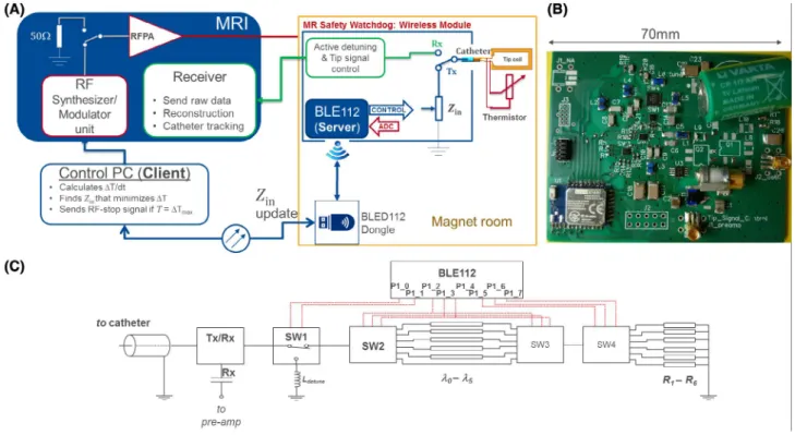
A schematic of the wireless MRsWD hardware module is shown in Figure 1. During the transmit (Tx) cycle (i.e., RF transmission), an integrated RF switch module connects the active catheter to the impedance control unit of the MRsWD using the system-provided DC bias signals. The MRsWD controls impedance by connecting a variable input
imped-ance, Zin, to the active catheter. The active catheter contained
a distal tip loop coil, which was connected to the proximal
end by a coaxial cable.65 In the MRsWD, the values of the
complex impedance are changed by n= 0, 1, … , 5 different
n⋅𝜆∕24 (at 123.2 MHz) line high-pass “tee” circuits, and
6 resistive loads, R1-6 = {0, 10, 27, 75, 220, 2200} Ω, which
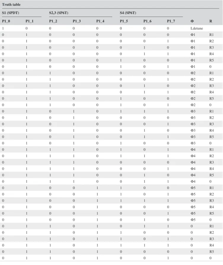
are selected by 3 single-pole-six-throw (SP6T) switches (JSW6-33DR+; Mini-Circuits, Brooklyn, NY). The truth
table for switch states and the resulting 36 input imped-ance values are given in Table 1 and shown in Figure 2. One single-pole-double-throw (SPDT) switch (HSWA2-30DR+; Mini-Circuits) was used to choose between the SP6T chain and an inductive termination used for active detuning. Tx/Rx (transmit/receive) mode switching was achieved by ADG918 (Analog Devices, Inc., Norwood, MA) that is controlled by the active detuning signal provided by the MRI system. The circuit board layouts, schematics, and production files along with the bill of materials can be found at https ://github. com/aliba z/MRsaf etyWa tchdog. MRsWD was powered by a nonmagnetic 3.6-V battery (Xeno XL-060F; Xeno Energy, Hwaseong-si, Korea). The circuit was placed inside a plastic box shielded with 3 M of copper tape, which had a 10 ×
10 mm2 aperture to enable wireless communication between
the MRsWD and an external control computer.
2.2
|
Temperature monitoring
Temperature increase at the tip of the catheter was moni-tored by the GaAs-Crystal– based fiber-optical tempera-ture probes (FOTPs) of a 4-channel calibrated thermometer (FOTEMP; Optocon AG, Dresden, Germany) and a 10-kΩ NTC thermistor (B57861S0103; EPCOS AG, Munich, Germany), which were placed in close vicinity to the loop
FIGURE 1 MR safety watchdog. (A) Functional diagram. The feedback loop between the MRI system and wireless module is controlled by an external PC. Communication with the wireless module is done by a USB dongle that is extended inside the Faraday’s cage by a fiber-optical cable. Four thermistors can be attached to the module, yet to avoid extra cables, a single thermistor is placed at the tip, where the catheter’s coaxial cable is used both for MR signal transmission and thermistor connection with the module. (B) A photo of the MR safety watchdog circuit board from top. (C) Simplified schematic of the module and the control pins on the BLE chip. ADC = analog to digital converter
coil at the tip. To avoid extra conducting cables in the setup, the thermistor was attached to the catheter and the microcoaxial cable was used to connect the thermistor to the Wheatstone bridge in the MRsWD, which was pow-ered directly from the main supply of the circuit. RF and
DC signals were decoupled using DC block capacitors (1 nF; Johanson Technology, Camarillo, CA) on the RF sig-nal path and bypass capacitors (100 nF and 10 nF; Johanson Technology) between the signal and ground paths of the Wheatstone bridge and those of the RF signal path. FOTPs
Truth table S1 (SPDT) S2,3 (SP6T) S4 (SP6T) Φ R P1_0 P1_1 P1_2 P1_3 P1_4 P1_5 P1_6 P1_7 1 0 0 0 0 0 0 0 Ldetune 0 1 0 0 0 0 0 0 Φ1 R1 0 1 0 0 0 0 0 1 Φ1 R2 0 1 0 0 0 0 1 0 Φ1 R3 0 1 0 0 0 0 1 1 Φ1 R4 0 1 0 0 0 1 0 0 Φ1 R5 0 1 0 0 0 1 0 1 Φ1 0 0 1 1 0 0 0 0 0 Φ2 R1 0 1 1 0 0 0 0 1 Φ2 R2 0 1 1 0 0 0 1 0 Φ2 R3 0 1 1 0 0 0 1 1 Φ2 R4 0 1 1 0 0 1 0 0 Φ2 R5 0 1 1 0 0 1 0 1 Φ2 0 0 1 0 1 0 1 1 1 Φ3 R1 0 1 0 1 0 0 0 0 Φ3 R2 0 1 0 1 0 0 0 1 Φ3 R3 0 1 0 1 0 0 1 0 Φ3 R4 0 1 0 1 0 0 1 1 Φ3 R5 0 1 0 1 0 1 0 0 Φ3 0 0 1 1 1 0 1 0 1 Φ4 R1 0 1 1 1 0 1 1 1 Φ4 R2 0 1 1 1 0 0 0 0 Φ4 R3 0 1 1 1 0 0 0 1 Φ4 R4 0 1 1 1 0 0 1 0 Φ4 R5 0 1 1 1 0 0 1 1 Φ4 0 0 1 0 0 1 1 0 0 Φ5 R1 0 1 0 0 1 1 0 1 Φ5 R2 0 1 0 0 1 1 1 1 Φ5 R3 0 1 0 0 1 0 0 0 Φ5 R4 0 1 0 0 1 0 0 1 Φ5 R5 0 1 0 0 1 0 1 0 Φ5 0 0 1 1 0 1 0 1 1 0 R1 0 1 1 0 1 1 0 0 0 R2 0 1 1 0 1 1 0 1 0 R3 0 1 1 0 1 1 1 1 0 R4 0 1 1 0 1 0 0 0 0 R5 0 1 1 0 1 0 0 1 0 0
and the thermistor had a temperature sampling rate of 10 Sa/s and at 5 Sa/s, respectively. The precision of FOTPs and the thermistor was ±0.1 and ±0.02 K, respectively.
2.3
|
Bluetooth module and control software
A Bluetooth Low Energy (BLE) radio version 4.0 (BLE112-A; Bluegiga Technologies Ltd., Espoo, Finland) was used to connect the MRsWD in the MR system’s Faraday cage to an external PC (Figure 1). A server-client network scheme was implemented. For the client applica-tion on the external PC, a graphical user interface was devel-oped to processes serial commands for the BLE application programming interface. These BLE commands are received by a BLE dongle (BLED112; Bluegiga Technologies) by a fiber-optic USB adapter (USB 3.Optical; Corning GmbH HQ, Wiesbaden, Germany). The fiber-optical USB cable penetrates the magnet room’s Faraday cage through an integrated waveguide. BLE112’s scripting language was used to develop a stand-alone server application on the MRsWD. The server processes the requests from the cli-ent. Peripheral requests, such as tip temperature acquisition and input impedance change requests and control over the power consumption of the module, were implemented in the server application. The overall latency was <500 ms. Data exchange between server and client application is established as an acknowledged operation.
Temperature measurements on the MRsWD were exe-cuted at a frequency of 5 Hz at 12-bit resolution. Impedance changes could be initiated from the client application by
sending a bit mask for the digital output pins of the SP6T
switches (i.e., the complex Zin). An alert signal code (“stop
RF” signal) could be sent by the client to reduce the RF power by 50 dB. For this task, the pin P1_0 was used, which originally controls SW1 when the feedback mode (cf. below) is disabled. The stop RF signal pin was always kept “high” to ensure operational safety in case of a broken connection between the client and server. The server application was designed with a low data overhead and processing.
To find the optimal Zin, a feedback algorithm was
pro-grammed to switch between the 36 different Zin values while
monitoring the temperature. A threshold temperature
dif-ference, ΔTsetZ, was defined and an impedance change was
initiated when ΔT(t) ≥ ΔTsetZ, where ΔT(t) is the
temper-ate difference to the last impedance change. At first, only the nλ/24 lines are tested, and the best value (i.e., the lowest temperate change ΔT/dt) is selected. Then, the 6 different resistive terminations are tested, and, finally, another iteration
is applied to find the optimal nλ/24 line. If ΔTmax is reached
during the iterations, the MRsWD sends an “RF stop” signal.
2.4
|
Experimental setup
Heating experiments were performed in 2 different 3T clinical MRI systems which have different transmit body coil configu-rations and thus E-field distributions: MRI-A (Magnetom Trio; Siemens AG, Erlangen, Germany) and MRI-B (Magnetom Prisma-Fit; Siemens AG). A 110-cm-long 8F cardiovascular catheter with nonmetallic Kevlar braiding was constructed
with a saddle coil at the tip (20 x 4 mm2), which was made of
35 µm of copper etched on flexible printed circuit board sub-strate (thickness, 50 µm). The tip coil was connected to an in-terface circuit at the proximal catheter end by a microcoaxial cable (outer diameter, 450 µm; Picocoax PCX40C05; Axon’ Kabel GmbH, Leonberg, Germany). The interface circuit was extended by a λ/4-long RG174-type coaxial cable that is con-nected to the microcoaxial cable and maps the impedance of the wireless control module to form Zin.
Following the American Society for Testing and Materials
(ASTM) guidelines,35 30 L of phantom gel (31 g/L of HEC,
CAS-No: 9004-62-0; Sigma-Aldrich, St. Louis, MO; and 1.55 g/L of NaCl, CAS-No: 7647-14-5; Carl Roth GmbH + Co. KG, Karlsruhe, Germany) was prepared. Conductivity was adjusted to 0.49 S/m using a conductivity meter (DiST; Hanna Instruments Deutschland GmbH, Vöhringen, Germany). To verify the dielectric properties at 123 MHz, a coaxial dielectric measurement kit was used as described in the appendix of an earlier work,66 and a relative permittivity, 𝜀
r= 81, and a
con-ductivity, 𝜎= 0.32 S/m, were measured using a network
ana-lyzer (ZVB4; Rhode & Schwarz GmbH & Co. KG, Munich, Germany). A LEGO (LEGO, Billund, Denmark) plate glued to the bottom of the ASTM phantom was used for reproducible
FIGURE 2 Reflection coefficients for the corresponding impedance values are displayed on the Smith chart
catheter and temperature probe holder positioning. The ASTM gel was kept in the magnet room for 24 hours for thermal equilibration. Thermistor and FOTPs were calibrated using a thermometer (testo 900; Testo SE & Co. KGaA, Lenzkirch,
Germany) to avoid temperature offsets.67
A rotating holder was used for fine adjustment of the tem-perature probe positioning at the tip of the partially immersed catheter (Figure 3A). Resonant modes of insertion lengths were found using the analytical model (Supporting Information Video S1) and verified experimentally by changing the im-mersed portion of the catheter with 10-mm steps. An insertion length of 14 cm was found to be a worse case. Local SAR dis-tribution around the tip coil was simulated using an FDTD-based solver (Sim4Life 4.4; ZMT Zurich MedTech AG, Zurich, Switzerland) to verify the probe placement (Figure 3B).
2.5
|
RF-induced heating measurements
A high-SAR pulse sequence that applies a single rectangular RF pulse of 2-ms duration per TR = 30 ms was used in RF-induced heating tests. The applied RF pulse had a peak volt-age amplitude of 318.5 V. The system-reported whole-body and exposed-body SAR values were 2.9 and 4.6 W/kg for MRI-A and 1.9 and 3.1 W/kg for MRI-B, respectively. Total RF exposure time was set with the number of averages and number of repetitions.
To test the effect of each impedance setting, Zin, on ΔT,
MRsWD was run in manual mode (i.e., the feedback modus was switched off) and a 1-minute RF pulse sequence was
ap-plied for each manually set Zin (cf., Figure 2), followed by
a 6-minute cool-down period. Afterwards, a 15-minute-long
RF pulse sequence was applied for each of the Z
optimal and
Z
least_optimal cases among all available Zin. Finally, the feedback modus was switched on, and the performance of MRsWD was observed during a 15-minute-long RF exposure using both FOTPs and the thermistor.
2.6
|
Input impedance Z
inIn this study, Zin is designated as the differential mode
im-pedance of a coaxial line, and, by definition, it is expected to affect only the balanced currents. In the setup, balanced currents could be generated in 2 possible ways: (1) unbal-anced currents from tangential incident fields coupled to the outer conductor could leak into the inner conductor by
capacitive coupling or through the apertures68; (2)
mag-netic field coupled to the loop coil at the tip generates bal-anced currents along the coaxial line. The latter mechanism is counterintuitive given that the E fields generated by the balanced currents are not expected to generate significant heating, because the size of the loop is rather small, and during the Tx cycle it is not tuned. To investigate this, the
FIGURE 3 Catheter and FOTP positioning. (A) Rotating holder for positioning and fixation of the FOTPs. Lego pieces and a board mounted on the bottom of the ASTM phantom were used to fix the rotating holder and for positioning of the catheter. (B) FDTD simulations show that the highest local SAR is expected just above the conductor of the loop coil at the tip. (C) SAR values plotted on the green line along the z-axis indicates higher SAR close to the terminals of the loop coil. Experiments validated a higher temperature rise at the tip than the regions close to the soldering points
temperature at the tip of the catheter was measured under a high-SAR protocol, and, without moving the catheter, probes, or the setup, the connection between the loop coil and the inner conductor of the coaxial line was cut, and then the measurements were repeated. To further investi-gate the magnetic coupling mechanism, FDTD simulations were performed with the loop coil oriented both horizon-tally and vertically (Supporting Information Figure S1). Here, the incident E field was constant, and the H field changes. In the simulation, E-field vector field maps and SAR maps were calculated. Details of the measurement and simulation protocols can be found in the supplemen-tary material (Supporting Information).
3
|
RESULTS
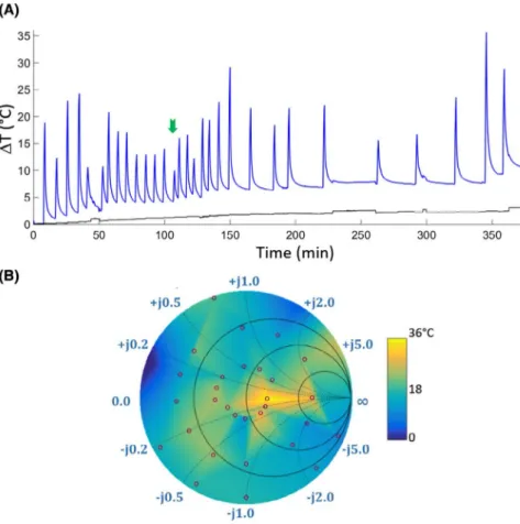
Results of the temperature measurements for each Zin
dur-ing 1-minute-long RF pulse at the MRI-B system are shown
in Figure 4. Zin was set following the order in the truth table
given in Figure 2. Z
optimal was found for λ/2 line with R = 27 Ω
at the terminal, resulting in a temperature rise of 6.7 K (indi-cated by the green arrow in Figure 4A). Maximum temper-ature-rise values are also mapped onto a color-coded Smith chart in Figure 4B. Temperature values from 1-minute
meas-urements for different Zin values were plotted on the Smith
chart in color and interpolated to cover the whole Smith chart
using available MATLAB functions (The MathWorks, Inc., Natick, MA) based on Delaunay triangulation of the 30
sam-ple points.69 The measured impedance values are indicated by
the red circles. The maximum temperature increase of 22.7°C
was measured at the tip of the catheter. For Z
optimal, slope of the
linear fit to the temperature curve within the first 5 seconds, ΔT/dt = 0.16 K/s, which is 84% slower than ΔT/dt = 0.98 K/s for Z
least_optimal.
FOTPs and the thermistor yielded similar curves for 1-minute heating experiments (Supporting Information Figure S2). Ripples with amplitude of ±0.06 K were observed every 38 seconds, which can be attributed to the increasing energy consumption during the transmit cycles of the BLE.
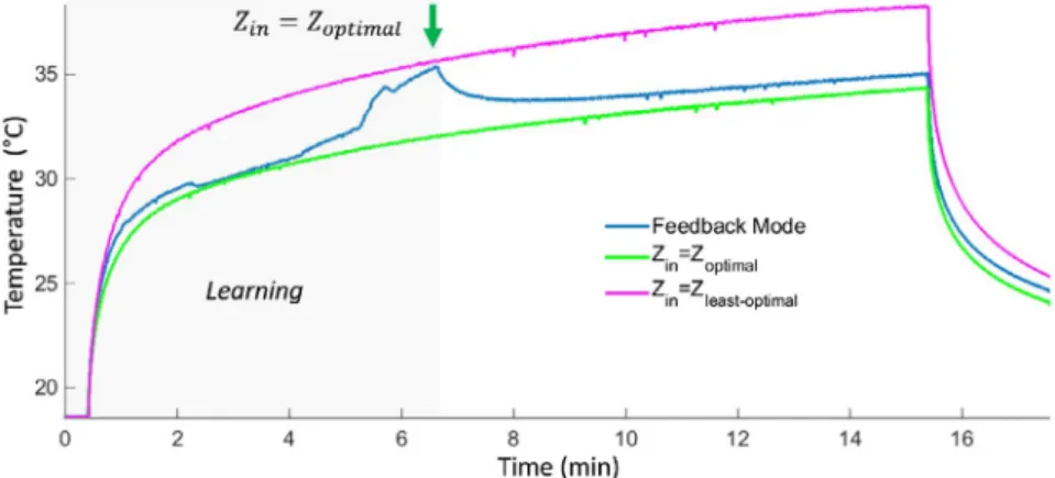
The feedback mode was run using the temperature data acquired with the thermistor. In Figure 5, 3 consecutive temperature measurements during 15-minute-long RF pulse are shown for the system MRI-A. For the feedback mode, ΔTSetZ = 1 K and ΔTmax = 30 K were set to demonstrate the
effect of the real-time impedance change. The blue line in-dicates the temperature increase while MRsWD is in feed-back mode. The black line shows the temperature curve for
Z
least_optimal and the green line for Zoptimal. A decrease in
tem-perature is observed when the optimal input impedance was found at t = 6.3 minutes. Maximum temperature rises are measured as 19.7, 16.5, and 15.8 K at the end of the
feed-back mode, Z
least_optimal, and Zoptimal, respectively. Ripples
on the thermistor data measured a peak-peak amplitude of
FIGURE 4 (A) Temperature measurements under 1 minute of a high SAR protocol (system-reported whole-body-SAR of 1.6 W/kg). Blue line plots the measurements from the FOTP placed at the tip of the loop coil; black line plots the background temperature. Impedance values were set manually through the MRsWD user interface. The optimal impedance, Zoptimal, is marked with a green arrow.
(B) The maximum change of temperature (i.e., ΔTmax) is mapped on a color-coded Smith chart
0.4 K during the 15-minute-long RF exposure. Negative spikes with an amplitude up to 6 K were also observed, which were smoothed out by a median filter.
In Figure 6, temperature measurements performed in the system MRI-B are shown. For the feedback mode, ΔTSetZ = 0.1 K and ΔTmax = 5 K were set. Resulting ΔTmax
at the end of the 5-minute RF exposure was 4.4 and 3.7 K for fixed Zin= Z
least_optimal and the feedback mode, respectively.
Z
optimal was found for λ/4 line with R = 10 Ω at the
termi-nal, that is, an equivalent impedance of Z = 32.3 + j247 Ω. The feedback mode operation MRsWD delayed reaching the 3 K temperature rise by 54 seconds compared to the
Z
least_optimal setting, where a 3 K temperature rise was reached
in 48 seconds.
The results of the magnetic field coupling measurements show that the heating was less when the loop coil was cut,
and that Zin has an effect on tip heating only when the loop
is connected (Supporting Information Figure S3; please cf. Supporting Information Part 1 for details). FDTD simula-tions showed that the tip SAR and E-field distribusimula-tions are dependent on the orientation of the loop coil (Supporting Information Figures S4 and S5; please cf. Supporting Information Part 2 for details).
4
|
DISCUSSION
We presented a novel interface circuit for active catheters, which functions as a safety watchdog that minimizes RF power at the output of the MRI system’s small signal unit. Electrical control over both Rx and Tx cycles of a sequence is realized. In the feedback mode, the system may not null the currents induced on the catheters and the reduction in heating might not correspond to an unsafe to safe transition for the devices; however, hazardous RF-related heating problems during interventional procedures with active catheters can be prevented using the proposed system to switch off RF power when temperature rise exceeds the specified threshold.
4.1
|
Temperature monitoring
FOTP measurements were used as a reference to compare thermistor readings. Embedded FOTPs can also be used in
catheters, which was demonstrated in a previous work.70 An
embedded thermistor was used for the experimental dem-onstration of the study. Using thermistors for temperature monitoring at the tip of a pacemaker lead during MRI was
FIGURE 5 Fifteen-minute-long high-SAR RF pulse temperature measurements in the system MRI-A for feedback mode, and fixed impedances: Zoptimal and Zleast_optimal. A decrease in temperature is observed when the optimal input impedance was found at t = 6.3 minutes. Maximum temperature rises are measured as 19.72, 16.52, and 15.78 K at the end of the feedback mode, Zleast_optimal, and Zoptimal, respectively
FIGURE 6 Five-minute-long high-SAR RF pulse temperature measurements in the system MRI-B for feedback modes and fixed impedance Zleast_optimal. A decrease in temperature is observed when the optimal input impedance was found at
t = 36 seconds. Maximum temperature values reached were 22.4 and 21.75 °C at the end of the Zleast_optimal and feedback mode, respectively
presented earlier.44 In Taber and Hayman,71 the performance
of various thermistors was reported to be consistent with Fluoroptic temperature probe measurements during MRI. Although the thermistor has a high impedance, the induced currents along the microcoaxial cable might affect the tem-perature measurements. We have verified that the currents along the microcoaxial cable have negligible effect on the thermistor readings by measuring the temperature rise when the thermistor and the loop coil, which are attached to the microcoaxial cable, were separated. The distance between those was increased to approximately 7 cm, and a maximum temperature rise of 0.5 K was measured, whereas the back-ground temperature rise was 0.3 K during a 5-minute-long RF pulse exposure with a system-reported whole-body SAR of 3.8 W/kg. Thermistor and FOTP measurements were also consistent when they were immersed in a water bath, and the temperature of the bath was increased gradually by adding hot water.
In this study, thermistor legs were directly connected by the catheter’s coaxial cable to avoid extra conducting cables. Artifacts (spikes) were observed during the heating exper-iments and, despite the use of RF decoupling capacitors and bypass capacitors, high-power RF signals from the MR scanner could not be cancelled completely. The very low continuous ripple (±0.06 K) is attributable to voltage reg-ulation problems, which are caused by the BLE radio con-nection events (the communication protocol is discrete, and every connection event leads the BLE module to draw a hun-dred times more current, which cannot be compensated by the integrated regulator of BLE112). These issues, however, did not bias the outcome of this study—in the future, extra shielding of thermistors will be used to reduce the spikes, or using a different method for temperature measurement,
such as embedded FOTPs, thermos-acoustic ultrasound,72 or
MRI-based methods73 can be applied.
In Supporting Information Figure S2, thermistor mea-surements indicate higher ΔT than FOPTs. One of the reasons might be the effect of the location, because the tem-perature measurements of the fiber optic temtem-perature probe (FOTP1) have a slight latency compared to the thermistor measurements. A distance to the hotspot results in measur-ing the diffused temperature from the hotspot. This effect is clearly observed in the measurements from FOTP2. It should also be noted that the FOTPs have location sensitivi-ties in the order of µm. In addition to the location effect, the thermistor’s time constant is higher than fiber-optical probes. The differences during the cooling cycle can be attributed to the difference in time constants. The hotspot locations were determined from the FDTD simulations. However, it is a limitation of thermistor-based measurements that if the hotspot location is not the exact measurement location, ΔT is lower than the maximum value, which may cause a late response by the MRsWD.
4.2
|
Feedback mechanism
Another limitation of the current setup is the total time
required for the feedback algorithm to find the Zoptimal value:
Currently, it is slow given that it is based on temperature measurements. However, as a proof of principle, temperature is a more reliable measure for the potential risks to living tissue than current- or field-based measures. In the future, improved versions of the setup toward a rapid search mecha-nism can be designed using feedback from current or field sensors, where lower Tx powers would be sufficient to es-timate the tip SAR. However, a rigorous investigation is re-quired to relate current or field measurements to SAR or ΔT. A current measurement at the circuit side (i.e., at the input of the interface circuit from catheter side similar to
Etezadi-Amoli et al,74 or E-field measurement using electro-optical
sensors75 at the tip of the catheter) needs to be correlated to
temperature rise for various conditions, which is beyond the scope of this study.
One of the most useful aspects of the MRsWD is the ability to stop high-power RF exposure by attenuating the Tx signal at the output of the small signal unit using an SPDT switch. Alternatively, RF power can be reduced, in-stead of switching it off. Insertion length of the active guid-ing catheter changes dynamically durguid-ing an interventional operation, and handling the catheter would change the criti-cal insertion length. When such an instant change stops RF power transmission, feedback mode can be reactivated by using lower RF power, after the equilibrium temperature is reached. As previously mentioned, use of current or field sensors might accelerate response to the instant changes by eliminating the time needed for energy to be transferred to a detectable temperature rise. Additionally, sampling rate of the temperature measurements can be increased. In this study, the module with Bluetooth radio version 4.0 is the limiting factor for faster measurements. Recently, new mod-ules with increased data rate powered by Bluetooth 5.1 have
been released.76 A hybrid solution with a combination of
temperature and field measurements can also be imple-mented. Responses of the various impedance values can be obtained with low-power E-field measurements. Then, the candidate impedance value can be verified by temperature measurements.
Feedback algorithm can be reversed to find Z
least_optimal
(i.e., the worst case) for a more realistic safety evaluation of active catheters. Our previous work shows that tip SAR, as a function of input impedance, changes drastically when
in-sertion length or incident field changes.77 Although the input
impedance of a regular active catheter is fixed by the pre-determined detuning state, a range of impedances could be taken into consideration to better define the safety margins. It is also possible for Z
optimal and Zleast_optimal to be very close
Finding the Z
optimal strictly depends on the range of
avail-able impedance values given that Z
optimal and Zleast_optimal
might change drastically because of catheter placement or in-cident field configuration (Supporting Information Video S1). In the future, an analog range of impedances using varactors and pin diodes might increase the chance of finding optimal impedance within the available set of input impedance values. Searching among a large sample set requires a faster feedback mechanism using previously mentioned current- or field-based methods, which will be addressed in future studies.
To assess the resulting tissue heating, a tier 4 approach is recommended, where numerous test measurements and
demanding electromagnetic computations are required.78
Within the same consensus, a tier 3 approach was proposed as an efficient method to calculate RF-induced heating at the electrode of an implant lead based on the transfer function
(TF) method.24 Here, the implant/device and incident field
are decoupled and treated separately, reducing the compu-tational requirements. The product of the numerically cal-culated or measured TF and the tangential component of an arbitrary incident E field is integrated along the lead to esti-mate the SAR at the tip. The TF approach can also be used to evaluate MR safety of medical implants or devices. Although the TF approach allows a more comprehensive assessment of the worst-case field distribution, it is still dependent on the
medium properties and insertion length79 and thus does not
eliminate the need for real-time monitoring of temperature. Note that during temperature measurements, temperature was monitored both at the tip of the coil and at the junction of the coaxial line and loop coil (Figure 3A). In the measured cases, the temperature at the tip was higher than the other probe locations. However, changing the phase of the unbal-anced or balunbal-anced currents might result in shifting the hotspot spatially. Spatial distribution of heat energy should be inves-tigated under different conditions using numeric simulations.
4.3
|
Input impedance Z
inIn general, Zin is transformed to the input of the tip coil as
an equivalent impedance. Measurements with the cut tip coil
showed that Zin controls the amount and phase of the
cur-rent induced by magnetic coupling, which interferes with the unbalanced currents destructively or constructively. Furthermore, simulations proved that phase and magnitude of the coupled current are affected also when the coil is ro-tated. Temperature measurements further confirm that the SAR at the tip, which is a result of the energy deposition of the fields generated by both unbalanced and balanced
cur-rents, can be controlled by changing Zin.
In a previous work,64 an implantable pulse generator
case was modeled as an equivalent voltage source given that it affects the current pattern along the lead. A complex
impedance term was also introduced to model the interac-tion between the case and lead. This fact was demonstrated
in Acikel et al,63 where the capacitance between the lead and
case was changed resulting in a change of the electrode tip heating. In this study, the impedance between the shielded box and the outer conductor of the coaxial line was kept constant by electrically separating them. Thus, the effect of
Zin was investigated separately. In future refinements, Zin
and the impedance between the shielded box and the outer conductor of the coaxial line will need to be investigated simultaneously with a faster feedback mechanism using E-field or current sensors.
5
|
CONCLUSION
This study demonstrates feasibility of an automated wireless impedance control and circuit, MRsWD, as an alternative or complementary approach to reduce or prevent risks of RF-induced heating of interventional devices.
ORCID
Berk Silemek https://orcid.org/0000-0001-8227-3632
Thomas Lottner https://orcid.org/0000-0003-3215-7582
REFERENCES
1. Ackerman JL, Offutt MC, Buxton RB, Brady TJ. Rapid 3D track-ing of small rf coils. In Proceedtrack-ings of the 5th Annual Meettrack-ing of the SMRM, Montréal, Québec, Canada, 1986. p. 1131.
2. Dumoulin CL, Souza SP, Darrow RD. Real-time position moni-toring of invasive devices using magnetic resonance. Magn Reson Med. 1993;29:411–415.
3. Susil RC, Yeung CJ, Halperin HR, Lardo AC, Atalar E. Multifunctional interventional devices for MRI: A combined elec-trophysiology/MRI catheter. Magn Reson Med. 2002;47:594–600. 4. Spuentrup E, Ruebben A, Schaeffter T, Manning WJ, Günther
RW, Buecker A. Magnetic resonance–guided coronary artery stent placement in a swine model. Circulation. 2002;105:874–879. 5. Bock M, Wacker FK. MR-guided intravascular interventions:
tech-niques and applications. J Magn Reson Imaging. 2008;27:326–338. 6. Fritz J, Thomas C, Clasen S, Claussen CD, Lewin JS, Pereira PL.
Freehand real-time MRI-guided lumbar spinal injection proce-dures at 1.5 T: feasibility, accuracy, and safety. Am J Roentgenol. 2009;192:161–167.
7. van den Bosch MAAJ, Daniel BL, Pal S, et al. MRI-guided needle localization of suspicious breast lesions: results of a freehand tech-nique. Eur Radiol. 2006;16:1811–1817.
8. Todd N, Diakite M, Payne A, Parker DL. In vivo evaluation of multi-echo hybrid PRF/T1 approach for temperature monitoring during breast MR-guided focused ultrasound surgery treatments. Magn Reson Med. 2014;72:793–799.
9. Campbell-Washburn AE, Tavallaei MA, Pop M, et al. Real-time MRI guidance of cardiac interventions. J Magn Reson Imaging. 2017;46:935–950.
10. Kurpad KN, Unal O. Multimode intravascular RF coil for MRI-guided interventions. J Magn Reson Imaging. 2011;33:995–1002.
11. Bottomley PA, Andrew ER. RF magnetic field penetration, phase shift and power dissipation in biological tissue: implications for NMR imaging. Phys Med Biol. 1978;23:630–643.
12. Buchli R, Boesiger P, Meier D. Heating effects of metallic implants by MRI examinations. Magn Reson Med. 1988;7:255–261. 13. Gimbel JR, Johnson D, Levine PA, Wilkoff BL. Safe performance
of magnetic resonance imaging on five patients with permanent cardiac pacemakers. Pacing Clin Electrophysiol. 1996;19:913–919. 14. Smith CD, Kildishev AV, Nyenhuis JA, Foster KS, Bourland
JD. Interactions of magnetic resonance imaging radio frequency magnetic fields with elongated medical implants. J Appl Phys. 2000;87:6188–6190.
15. Konings MK, Bartels LW, Smits HF, Bakker CJ. Heating around intravascular guidewires by resonating RF waves. J Magn Reson Imaging. 2000;12:79–85.
16. Nitz WR, Oppelt A, Renz W, Manke C, Lenhart M, Link J. On the heating of linear conductive structures as guide wires and catheters in interventional MRI. J Magn Reson Imaging. 2001;13:105–114. 17. Yeung CJ, Atalar E. A Green’s function approach to local rf heating
in interventional MRI. Med Phys. 2001;28:826–832.
18. Yeung CJ, Susil RC, Atalar E. RF safety of wires in interventional MRI: using a safety index. Magn Reson Med. 2002;47:187–193. 19. Yeung CJ, Susil RC, Atalar E. RF heating due to conductive wires
during MRI depends on the phase distribution of the transmit field. Magn Reson Med. 2002;48:1096–1098.
20. Rezai AR, Finelli D, Nyenhuis JA, et al. Neurostimulation systems for deep brain stimulation: in vitro evaluation of magnetic reso-nance imaging-related heating at 1.5 tesla. J Magn Reson Imaging. 2002;15:241–250.
21. Park SM, Kamondetdacha R, Amjad A, Nyenhuis JA. MRI safety: RF-induced heating near straight wires. In INTERMAG Asia 2005. Digests of the IEEE International Magnetics Conference, Nagoya, Japan, 2005. pp. 1243–1244.
22. Nyenhuis JA, Park SM, Kamondetdacha R, Amjad A, Shellock FG, Rezai AR. MRI and implanted medical devices: Basic interactions with an emphasis on heating. IEEE Trans Device Mater Reliab. 2005;5:467–479.
23. Nitz WR, Brinker G, Diehl D, Frese G. Specific absorption rate as a poor indicator of magnetic resonance-related implant heating. Invest Radiol. 2005;40:773–776.
24. Park SM, Kamondetdacha R, Nyenhuis JA. Calculation of MRI-induced heating of an implanted medical lead wire with an electric field transfer function. J Magn Reson Imaging. 2007;26:1278–1285.
25. Mattei E, Triventi M, Calcagnini G, et al. Temperature and SAR measurement errors in the evaluation of metallic linear structures heating during MRI using fluoroptic® probes. Phys Med Biol. 2007;52:1633–1646.
26. Mattei E, Triventi M, Calcagnini G, et al. Complexity of MRI in-duced heating on metallic leads: Experimental measurements of 374 configurations. Biomed Eng Online. 2008;7:11.
27. Nordbeck P, Weiss I, Ehses P, et al. Measuring RF-induced currents inside implants: impact of device configuration on MRI safety of cardiac pacemaker leads. Magn Reson Med. 2009;61:570–578. 28. Bottomley PA, Kumar A, Edelstein WA, Allen JM, Karmarkar PV.
Designing passive MRI-safe implantable conducting leads with electrodes. Med Phys. 2010;37:3828–3843.
29. Cabot E, Lloyd T, Christ A, et al. Evaluation of the RF heating of a generic deep brain stimulator exposed in 1.5 T magnetic resonance scanners. Bioelectromagnetics. 2013;34:104–113.
30. Kozlov M, Schaefers G. Radio frequency induced heating of an insulated wire during magnetic resonance imaging. In 38th Annual International Conference of the IEEE Engineering in Medicine and Biology Society (EMBC), Orlando, FL, 2016. pp. 6238–6241. 31. Bhusal B, Bhattacharyya P, Baig T, Jones S, Martens M.
Measurements and simulation of RF heating of implanted stereo-electroencephalography electrodes during MR scans. Magn Reson Med. 2018;80:1676–1685.
32. Maier SE, Wildermuth S, Darrow RD, Watkins RD, Debatin JF, Dumoulin CL. Safety of MR tracking catheters. In Proceedings of the 3rd Scientific Meeting and Exhibition of the Society of Magnetic Resononance, Nice, France, 1995. p. 497.
33. Ladd ME, Quick HH, Debatin JF, von Schulthess GK, Mckinnon GC. Resonant heating of intravascular RF coils. In Proceedings of the 6th Scientific Meeting and Exhibition of the ISMRM, Sydney, Australia, 1998. p. 473.
34. Krafft A, Müller S, Umathum R, Semmler W, Bock M. B1 field- insensitive transformers for RF-safe transmission lines. MAGMA. 2006;19:257–266.
35. American Society for Testing and Materials International. Designation: ASTM F2182–11a, standard test method for mea-surement of radio frequency induced heating near passive implants during magnetic resonance imaging. West Conshohocken, PA: American Society for Testing and Materials International; 2011. 36. Langman DA, Goldberg IB, Judy J, Paul Finn J, Ennis DB. The
dependence of radiofrequency induced pacemaker lead tip heating on the electrical conductivity of the medium at the lead tip. Magn Reson Med. 2012;68:606–613.
37. Liu J, Kurpad KN, Stadnik P, et al. MRI RF safety of active implant-able medical devices (AIMDs): experimental study of the effect of conductivity of tissue simulating media. In Proceedings of the 26th Annual Meeting of the ISMRM, Paris, France, 2018. p. 1473. 38. Bhusal B, Baig T, Bhattacharyya P, Jones S, Martens M. Resonant
heating study of a partially immersed implant in ASTM phantom and human model. In Proceedings of the 26th Annual Meeting of the ISMRM, Paris, France, 2018. p. 1471.
39. Yeung CJ, Karmarkar P, McVeigh ER. Minimizing RF heating of conducting wires in MRI. Magn Reson Med. 2007;58:1028–1034. 40. Min X, Sison S. Impact of mixed media on transfer functions with a
pacemaker system for estimation of RF heating during MRI scans. Comput Cardiol. 2017;44. Available at: http://www.cinc.org/archi ves/2017/pdf/272-135.pdf. Accessed December 30, 2019. 41. Zeng QI, Liu J, Angelone LM, et al. Investigation of RF-induced
heating near interventional catheters at 1.5 T MRI: a combined modeling and experimental study. IEEE Trans Electromagn Compat. 2019;61:1423–1431.
42. Nordbeck P, Weiss I, Ehses P, et al. Measuring RF-induced currents inside implants: Impact of device configuration on MRI safety of cardiac pacemaker leads. Magn Reson Med. 2009;61:570–578. 43. Neufeld E, Gosselin M-C, Murbach M, Christ A, Cabot E, Kuster
N. Analysis of the local worst-case SAR exposure caused by an MRI multi-transmit body coil in anatomical models of the human body. Phys Med Biol. 2011;56:4649–4659.
44. Silemek B, Acikel V, Oto C, et al. A temperature sensor implant for active implantable medical devices for in vivo subacute heating tests under MRI. Magn Reson Med. 2018;79:2824–2832.
45. Basar B, Rogers T, Ratnayaka K, et al. Segmented nitinol guidewires with stiffness-matched connectors for cardiovascular magnetic reso-nance catheterization: preserved mechanical performance and free-dom from heating. J Cardiovasc Magn Reson. 2015;17:105.
46. Yildirim KD, Basar B, Campbell-Washburn AE, Herzka DA, Kocaturk O, Lederman RJ. A cardiovascular magnetic resonance (CMR) safe metal braided catheter design for interventional CMR at 1.5 T: freedom from radiofrequency induced heating and pre-served mechanical performance. J Cardiovasc Magn Reson. 2019;21:16.
47. Ladd ME, Quick HH. Reduction of resonant RF heating in in-travascular catheters using coaxial chokes. Magn Reson Med. 2000;43:615–619.
48. Weiss S, Vernickel P, Schaeffter T, Schulz V, Gleich B. Transmission line for improved RF safety of interventional devices. Magn Reson Med. 2005;54:182–189.
49. Bottomley PA, Kumar A, Edelstein WA, Allen JM, Karmarkar PV. Designing passive MRI-safe implantable conducting leads with electrodes. Med Phys. 2010;37:3828.
50. Ocali O, Atalar E. Intravascular magnetic resonance imaging using a loopless catheter antenna. Magn Reson Med. 1997;37: 112–118.
51. Nordbeck P, Fidler F, Friedrich MT, et al. Reducing RF-related heating of cardiac pacemaker leads in MRI: implementation and experimental verification of practical design changes. Magn Reson Med. 2012;68:1963–1972.
52. Fandrey S, Weiss S, Müller J. A novel active MR probe using a miniaturized optical link for a 1.5-T MRI scanner. Magn Reson Med. 2012;67:148–155.
53. Ratnayaka K, Faranesh AZ, Guttman MA, Kocaturk O, Saikus CE, Lederman RJ. Interventional cardiovascular magnetic resonance: still tantalizing. J Cardiovasc Magn Reson. 2008;10:62.
54. Schenck JF, Jolesz FA, Roemer PB, et al. Superconducting open-configuration MR imaging system for image-guided therapy. Radiology. 1995;195:805–814.
55. Eryaman Y, Guerin B, Akgun C, et al. Parallel transmit pulse de-sign for patients with deep brain stimulation implants. Magn Reson Med. 2015;73:1896–1903.
56. Graesslin I, Krueger S, Vernickel P, Achtzehn J, Nehrke K, Weiss S. Detection of RF unsafe devices using a parallel transmission MR system. Magn Reson Med. 2013;70:1440–1449.
57. Ellenor CW, Stang PP, Etezadi-Amoli M, Pauly JM, Scott GC. Offline impedance measurements for detection and mitigation of dangerous implant interactions: an RF safety prescreen. Magn Reson Med. 2015;73:1328–1339.
58. Eryaman Y, Turk EA, Oto C, Algin O, Atalar E. Reduction of the radiofrequency heating of metallic devices using a dual-drive bird-cage coil. Magn Reson Med. 2013;69:845–852.
59. Eryaman Y, Akin B, Atalar E. Reduction of implant RF heating through modification of transmit coil electric field. Magn Reson Med. 2011;65:1305–1313.
60. Etezadi-Amoli M, Stang P, Kerr A, Pauly J, Scott G. Controlling radiofrequency-induced currents in guidewires using parallel trans-mit. Magn Reson Med. 2015;74:1790–1802.
61. Gudino N, Sonmez M, Yao Z, et al. Parallel transmit excitation at 1.5 T based on the minimization of a driving function for device heating. Med Phys. 2015;42:359–371.
62. Özen AC, Lottner T, Bock M. Safety of active catheters in MRI: termination impedance versus RF-induced heating. Magn Reson Med. 2019;81:1412–1423.
63. Acikel V, Silemek B, Atalar E. Wireless control of induced radio- frequency currents in active implantable medical devices during MRI. Magn Reson Med. 2020;83:2370–2381.
64. Acikel V, Uslubas A, Atalar E. Modeling of electrodes and im-plantable pulse generator cases for the analysis of implant tip heat-ing under MR imagheat-ing. Med Phys. 2015;42:3922–3931.
65. Heidt T, Reiss S, Krafft AJ, et al. Real-time magnetic resonance imaging – guided coronary intervention in a porcine model. Sci Rep. 2019;9:8663.
66. Özen AC. A method of decoupling of radio frequency coils in magnetic resonance imaging: application to MRI with ultra short echo time concurrent excitation and acquisition. Ankara, Turkey: Bilkent University; 2013.
67. Buchenberg WB, Dadakova T, Groebner J, Bock M, Jung B. Comparison of two fiber-optical temperature measurement systems in magnetic fields up to 9.4 Tesla. Magn Reson Med. 2015;73:2047–2051.
68. Tesche FM, Ianoz M, Karlsson T. EMC Analysis Methods and Computational Models. New York, NY: Wiley Interscience; 1997.
69. Amidror I. Scattered data interpolation methods for electronic im-aging systems: a survey. J Electron Imim-aging. 2002;11:157–176. 70. Sonmez M, Saikus CE, Bell JA, et al. MRI active guidewire
with an embedded temperature probe and providing a distinct tip signal to enhance clinical safety. J Cardiovasc Magn Reson. 2012;14:38.
71. Taber KH, Hayman LA. Temperature monitoring during MR im-aging: comparison of fluoroptic and standard thermistors. J Magn Reson Imaging. 1992;2:99–101.
72. Dixit N, Stang PP, Pauly JM, Scott GC. Thermo-acoustic ultra-sound for detection of RF-induced device lead heating in MRI. IEEE Trans Med Imaging. 2018;37:536–546.
73. Rieke V, Butts PK. MR thermometry. J Magn Reson Imaging. 2008;27:376–390.
74. Etezadi-Amoli M, Stang P, Kerr A, Pauly J, Scott G. Interventional device visualization with toroidal transceiver and optically coupled current sensor for radiofrequency safety monitoring. Magn Reson Med. 2015;73:1315-1327.
75. Reiss S, Bitzer A, Bock M. An optical setup for electric field mea-surements in MRI with high spatial resolution. Phys Med Biol. 2015;60:4355–4370.
76. Collotta M, Pau G, Talty T, Tonguz OK. Bluetooth 5: a con-crete step forward toward the IoT. IEEE Commun Mag. 2018;56: 125–131.
77. Özen AC, Lottner T, Bock M. Safety of active catheters in MRI: termination impedance versus RF-induced heating. In Proceedings of the 27th Annual Meeting of the ISMRM, Montréal, QC, Canada, 2019. p. 154.
78. Technical Committee ISO/TC 150. ISO/TS 10974: assessment of the safety of magnetic resonance imaging for patients with an active implantable medical device. ed. 1, clause 10. Geneva, Switzerland: International Organization for Standardization; 2012.
79. Özen AC, Lottner T, Reiss S, Bitzer A, Bock M. Safety assess-ments in cascaded media using an electro-optic sensor-based transfer function measurement setup. In Proceedings of the 27th Annual Meeting of the ISMRM, Montréal, QC, Canada, 2019. p. 4184.
SUPPORTING INFORMATION
Additional Supporting Information may be found online in the Supporting Information section.
FIGURE S1 Simulation setup (A) with zoomed view of the
orthogonal coils (B)
FIGURE S2 Comparison of temperature curves acquired
using the FOTPs and the thermistor. The systematic differences between the FOTPs and the thermistor re-sult in slightly different heating and cooling curves. The difference between the maximum temperature values is less than 2K. The thermistor’s time constant is higher than that of FOTPs. The ripples on the thermistor data (high-lighted with a red circle) have a peak-peak amplitude of 0.12K
FIGURE S3 Comparison of heating curves for various input
impedance values A) when the regular loop coil connection was used B) when the loop coil and the inner conductor of the coaxial line was not connected
FIGURE S4 SAR maps (A,B) and SAR line plots (C) along
the green line for horizontal (A) and vertical (B) alignment of the loop coil
FIGURE S5 E field vectors for horizontal (A) and the
verti-cal orientation of the loop coil (B)
VIDEO S1 Insertion length vs. optimal impedance,
cal-culated using the analytical model in cascade of different media, as described in (62)
How to cite this article: Özen AC, Silemek B,
Lottner T, Atalar E, Bock M. MR safety watchdog for active catheters: Wireless impedance control with real-time feedback. Magn Reson Med. 2020;84:1048–