MLFMA Solutions of Transmission Problems
Involving Realistic Metamaterial Walls
¨
Ozg¨ur Erg¨ul
1,2, Alper ¨
Unal
2, and Levent G¨urel
1,2 1Department of Electrical and Electronics Engineering 2Computational Electromagnetics Research Center (BiLCEM)Bilkent University, TR-06800, Bilkent, Ankara, Turkey [email protected], [email protected], [email protected]
Abstract— We present the solution of multilayer metamaterial (MM) structures containing large numbers of unit cells, such as split-ring resonators. Integral-equation formulations of scat-tering problems are solved iteratively by employing a parallel implementation of the multilevel fast multipole algorithm. Due to ill-conditioned nature of the problems, advanced precondi-tioning techniques are used to obtain rapid convergence in the iterative solutions. By constructing a sophisticated simulation environment, we accurately and efficiently investigate large and complicated MM structures.
I. INTRODUCTION
After they were first fabricated in 2000 [1], metamaterials (MMs) have attracted a great amount of interest in the sci-entific community due to their useful electromagnetic proper-ties. These structures are usually constructed by periodically arranging unit cells in a host medium. In this paper, we specifically investigate MMs that contain split-ring resonators (SRRs) as basic building blocks. We do not assume any periodicity or homogeneity for these structures. We take into account that MMs are actually of finite extent, they exhibit interface properties, and their unit cells (SRRs) are interacting with each other. Our accurate simulations transform into large computational problems, which require special acceleration methods, such as the multilevel fast multipole algorithm (MLFMA) [2].
Fig. 1 presents the SRR geometry and its discretization used in our simulations. When the host medium has a relative
y
x
y
x
(a) (b)
Fig. 1. (a) An SRR geometry used in our simulations. (b) Discretization of the SRR with 84 triangles corresponding to 82 unknowns.
y
x
z
y
x
y
x
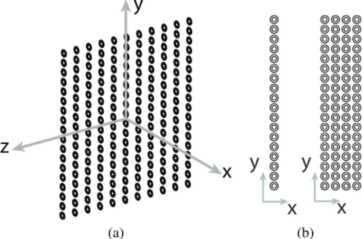
(a) (b)Fig. 2. An SRR array (1-layer MM wall). (b) Side views of 1-layer and 4-layer MM walls.
permittivity of 4.8 similar to the experimental case [3], this SRR resonates around 100 GHz [3]-[6]. In our simulation environment, SRRs are modeled by using perfectly-conducting surfaces with zero thickness. Then, the electric-field integral equation (EFIE) is employed to formulate the scattering prob-lems. However, matrix equations produced by EFIE are usually ill-conditioned and their iterative solutions are difficult [7]. In our case, quick convergence of the iterations is further inhibited by the resonant nature of MMs. Therefore, we employ advanced preconditioning techniques for the efficient solutions of MM problems.
Fig. 2 presents some examples of MM structures constructed by using SRRs. As depicted in Fig. 2(a), we arrange SRRs as a two-dimensional array in the z-y plane. In addition, we construct multilayer MM walls as shown in Fig. 2(b) by stacking the layers in the x direction. Periodicity of the unit cells are 263 µm, 263 µm, and 450 µm in the x, y, and z directions, respectively.
II. EFIE FORMULATION OFMETAMATERIALPROBLEMS
For perfectly-conducting objects, EFIE can be written di-rectly from the boundary condition for the tangential electric
90 GHz Y Axis (mm ) X Axis (mm) −15 −10 −5 0 −10 −5 0 5 10 −30 −20 −10 0 10 100 GHz Y Axis (mm ) X Axis (mm) −15 −10 −5 0 −10 −5 0 5 10 −30 −20 −10 0 10 110 GHz Y Axis (mm ) X Axis (mm) −15 −10 −5 0 −10 −5 0 5 10 −30 −20 −10 0 10 (a) 90 GHz Y Axis (mm ) X Axis (mm) −15 −10 −5 0 −10 −5 0 5 10 −30 −20 −10 0 10 100 GHz Y Axis (mm ) X Axis (mm) −15 −10 −5 0 −10 −5 0 5 10 −30 −20 −10 0 10 110 GHz Y Axis (mm ) X Axis (mm) −15 −10 −5 0 −10 −5 0 5 10 −30 −20 −10 0 10 (b)
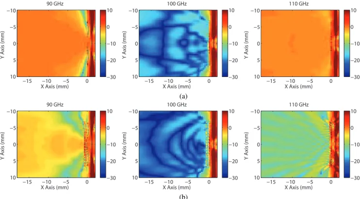
Fig. 3. Power transmission for (a) 1-layer and (b) 4-layer SRR walls. Each layer contains 51×29 SRRs. A shadowing effect is observed at 100 GHz due to an effective negative permeability induced in the medium.
field (in phasor notation with the e−iωt convention) as
ˆ t · ikη Z S dr0 · J(r0) + 1 k2∇ 0· J(r0)∇ ¸ g(r, r0) = −ˆt · Ei(r) (1) by expressing the scattered electric field in terms of the induced (unknown) surface current J(r). In (1), ˆt is any
tangential unit vector on the surface at the observation point
r, Ei(r) is the incident electric field, k = ω√µ² is the
wavenumber, η =pµ/² is the impedance of the host medium,
and
g(r, r0) =eikR
4πR ³
R = |r − r0|´ (2)
denotes the homogenous-space Green’s function.
For numerical solutions of MM problems, discretization of EFIE leads to N × N dense matrix equations as
N
X
n=1
ZE
mnan= vmE, m = 1, ..., N, (3)
where the matrix elements and the elements of the excitation vector are derived as
ZE mn= ikη Z Sm drtm(r) · Z Sn dr0g(r, r0) · b n(r0) +iη k Z Sm drtm(r) · Z Sn dr0∇0· b n(r0)∇g(r, r0) (4) and vmE = − Z Sm drtm(r) · Ei(r), (5)
respectively. In (4) and (5), Sm and Sn symbolize the spatial
supports of the mth testing function tm(r) and nth basis
function bn(r0), respectively. We apply a Galerkin scheme
and choose the basis and testing functions as Rao-Wilton-Glisson (RWG) functions defined on planar triangles [8]. The matrix equation in (3) is solved iteratively, and the matrix-vector products are accelerated by MLFMA.
Following the solution of the coefficients an, we obtain the
scattered electric and magnetic fields as
Es(r) = ikη N X n=1 Z Sn dr0g(r, r0)bn(r0)an +iη k N X n=1 Z Sn dr0∇0· b n(r0)∇g(r, r0)an (6) and Hs(r) = N X n=1 Z Sn dr0b n(r0) × ∇0g(r, r0)an, (7)
respectively. Then, the average power density at an observation point r is calculated as Pt av(r) = Pt(r)®= 1 2Re n Et(r) × [Ht(r)]∗o, (8)
where Et(r) = Ei(r)+Es(r) and Ht(r) = Hi(r)+Hs(r) are the total electric and magnetic fields, respectively. For a
85
90
95
100
105
110
−40
−30
−20
−10
0
10
Frequency (GHz)
Powe
r Tr
ans
mission (dB)
1 Layer
4 Layer
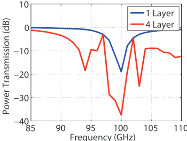
Fig. 4. Power transmission for 1-layer and 4-layer SRR walls as a function of frequency.
MM wall, we define the power transmission as
τ (r) = |P t av(r)| |Piav(r)| , (9) where Piav(r) = Pi(r)®=1 2Re n Ei(r) × [Hi(r)]∗ o (10) is the average incident power density due to external sources.
III. NUMERICALRESULTS
Fig. 3 demonstrates the power transmission results for 1-layer and 4-1-layer SRR walls at 90, 100, and 110 GHz. Each layer of the walls includes 51×29 SRRs. Power transmission is calculated on the z = 0 plane and SRR walls are located at x = 0. The source is a Hertzian dipole oriented in the y direction and located at x = 1.2 mm. Transmission region is on the left of the MM walls. Fig. 3(a) shows that the power transmission through the 1-layer wall is close to unity corresponding to 0 decibels (dB) at 90 and 110 GHz. In other words, the MM wall is transparent at these frequencies and the fields radiated from the dipole are transmitted through the structure. However, at 100 GHz, the wall becomes opaque and the transmitted power drops significantly. This is due to effective negative permeability induced in the medium, which is triggered by a physical resonance of the SRR structure.
When the number of layers increases, transmission prop-erties of the MM structures change significantly. Especially coupling among the layers leads to more oscillatory power transmission with respect to frequency. In addition, bandwidth of the resonance tends to increase with the inclusion of more layers. As an example, Fig. 3(b) presents the transmission re-sults for the 4×51×29 SRR wall. In addition to the shadowing at 100 GHz, we also observe relatively lower transmission at 90 and 110 GHz compared to the 1-layer results in Fig. 3(a). For a more quantitative comparison, Fig. 4 presents the power transmission calculated at a single point (x = −1.2 mm) as a function of frequency for the 1-layer and 4-layer structures.
85 90 95 100 105 110 100 101 102 103 104
Frequency (GHz)
Iterations
No PC BD SAI AMLFMAFig. 5. Number of GMRES iterations for the solution of a scattering problem involving a 1×51×29 SRR wall. Using a BD preconditioner, convergence cannot be achieved within 4000 iterations at 95 GHz.
Increasing the number of layers, power transmission becomes oscillatory and the stop-band region is not confined to a narrow band of frequencies around 100 GHz.
Fig. 5 presents the iteration counts for the solution of the scattering problem involving the 1×51×29 SRR wall. For a range of frequencies from 85 GHz to 110 GHz, iterative solutions are performed by a generalized-minimal-residual (GMRES) algorithm with no restart. We observe that the solution of the problem is extremely difficult at 95 GHz due to a numerical resonance of the MM structure. At this frequency, residual error can be reduced below 10−3 with
more than 1000 iterations without a preconditioner. Using a block-diagonal (BD) preconditioner accelerates the iterative solutions slightly for low frequencies, where the diagonal blocks involve large numbers of matrix elements. However, BD preconditioner becomes useless for higher frequencies. At the resonance frequency (95 GHz), using BD preconditioner is even worse than the no-preconditioner case; convergence cannot be achieved within 4000 iterations. By employing a sparse-approximate-inverse (SAI) preconditioner, iterative solutions are accelerated significantly, except for the resonance frequency. We note that this acceleration is provided at the cost of the increased setup time for the construction of the precon-ditioner [9]. Finally, to further accelerate the iterations, we employ a nested preconditioning scheme based on a flexible GMRES algorithm and an approximate MLFMA (AMLFMA) preconditioner [10]. Using this highly effective preconditioner, the number of iterations is only 244 at the resonance frequency, while it is less than 5 for ordinary frequencies.
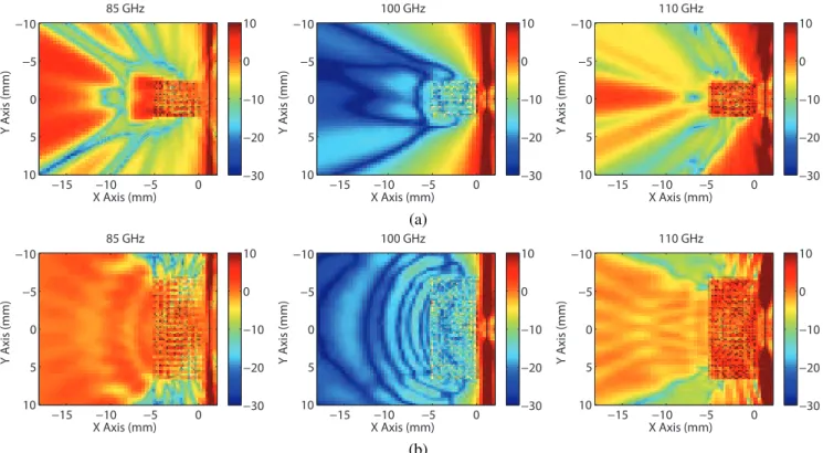
Finally, Fig. 6 presents the transmission results for very large MM walls involving 20 layers. The scattering problems are solved by MLFMA parallelized into 64 processes running on a cluster of quad-core Intel Xeon processors connected via an Infiniband network. Fig. 6(a) shows the power transmission for a 20×18×11 wall, which is discretized with 324,720 unknowns. In Fig. 6(b), power transmission is depicted for
85 GHz Y Axis (mm ) X Axis (mm) −15 −10 −5 0 −10 −5 0 5 10 −30 −20 −10 0 10 100 GHz Y Axis (mm ) X Axis (mm) −15 −10 −5 0 −10 −5 0 5 10 −30 −20 −10 0 10 110 GHz Y Axis (mm ) X Axis (mm) −15 −10 −5 0 −10 −5 0 5 10 −30 −20 −10 0 10 (a) 85 GHz Y Axis (mm ) X Axis (mm) −15 −10 −5 0 −10 −5 0 5 10 −30 −20 −10 0 10 100 GHz Y Axis (mm ) X Axis (mm) −15 −10 −5 0 −10 −5 0 5 10 −30 −20 −10 0 10 110 GHz Y Axis (mm ) X Axis (mm) −15 −10 −5 0 −10 −5 0 5 10 −30 −20 −10 0 10 (b)
Fig. 6. Transmission results for 20-layer SRR walls. Each layer involves (a) 18×11 and (b) 51×29 SRRs. A shadowing effect is observed at 100 GHz due to effective negative permeability induced in the medium.
a 20×51×29 wall, which is discretized with 2,425,560 un-knowns.
IV. CONCLUSIONS
We report our efforts for the fast and accurate solution of large MM structures constructed by SRRs. Scattering problems are formulated with EFIE and the resulting dense matrix equations are solved iteratively by MLFMA. We employ robust preconditioning techniques to obtain rapid convergence for the iterative solutions. By constructing a sophisticated simulation environment, we are able to investigate the transmission prop-erties of realistic MM structures involving large numbers of unit cells.
ACKNOWLEDGMENT
This work was supported by the Scientific and Technical Research Council of Turkey (TUBITAK) under Research Grants 105E172 and 107E136, by the Turkish Academy of Sciences in the framework of the Young Scientist Award Pro-gram (LG/TUBA-GEBIP/2002-1-12), and by contracts from ASELSAN and SSM.
REFERENCES
[1] D. R. Smith, W. J. Padilla, D. C. Vier, S. C. Nemat-Nasser, and S. Schultz, “Composite Medium with Simultaneously Negative Perme-ability and Permittivity,” Phys. Rev. Lett., vol. 84, 4184, 2000. [2] J. Song, C.-C. Lu, and W. C. Chew, “Multilevel fast multipole algorithm
for electromagnetic scattering by large complex objects,” IEEE Trans.
Antennas Propagat., vol. 45, no. 10, pp. 1488–1493, Oct. 1997.
[3] M. Gokkavas, K. G¨uven, I. Bulu, K. Aydın, R. S. Penciu, M. Kafesaki, C. M. Soukoulis, and E. ¨Ozbay, “Experimental demonstration of a left-handed metamaterial operating at 100 GHz,” Phys. Rev. B., vol. 73, no. 193103, 2006.
[4] ¨O. Erg¨ul, A. ¨Unal, and L. G¨urel, “Accurate modeling of metamaterials with MLFMA,” in Proc. European Conference on Antennas and
Prop-agation (EuCAP), 350094, 2006.
[5] ¨O. Erg¨ul, C¸. Yavuz, A. ¨Unal, and L. G¨urel, “Investigation of various metamaterial structures using multilevel fast multipole algorithm,” in
Proc. IEEE Antennas and Propagation Soc. Int. Symp., 2007, pp. 1845–
1848.
[6] L. G¨urel, ¨O. Erg¨ul, and A. ¨Unal, “Accurate analysis of metamaterials involving finite arrays of split-ring resonators and thin wires,” in Proc.
Progress in Electromagnetics Research Symposium (PIERS), 2007, pp.
470–473.
[7] L. G¨urel and ¨O. Erg¨ul, “Comparisons of FMM implementations employ-ing different formulations and iterative solvers,” in Proc. IEEE Antennas
and Propagation Soc. Int. Symp., vol. 1, 2003, pp. 19–22.
[8] S. M. Rao, D. R. Wilton, and A. W. Glisson, “Electromagnetic scatter-ing by surfaces of arbitrary shape,” IEEE Trans. Antennas Propagat., vol. AP-30, no. 3, 409–418, May. 1982.
[9] Y. Saad, Iterative Methods for Sparse Linear Systems. Philadelphia: SIAM, 2003.
[10] T. Malas, ¨O. Erg¨ul, and L. G¨urel, “Approximate MLFMA as an efficient preconditioner,” in Proc. IEEE Antennas and Propagation Soc. Int.
Symp., 2007, pp. 1289–1292.