MICROFLUIDIC DEVICE FOR SYNTHESIS OF CHITOSAN
NANOPARTICLES
Barbaros Cetin∗
Microfluidics & Lab-on-a-chip Research Group Mechanical Engineering Department
Ihsan Dogramaci Bilkent University Ankara 06800 TURKEY Email: barbaros.cetin@bilkent.edu.tr
Serdar Taze
Microfluidics & Lab-on-a-chip Research Group Mechanical Engineering Department
Ihsan Dogramaci Bilkent University Ankara 06800 TURKEY Email: serdar.taze@bilkent.edu.tr
Mehmet D. Asik
Nanotechnology and Nanomedicine Division Hacettepe University
Ankara 06800 TURKEY Email: mehmetdoganasik@gmail.com
S. Ali Tuncel
Nanotechnology and Nanomedicine Division Hacettepe University
Ankara 06800 TURKEY Email: atuncel@hacettepe.edu.tr
ABSTRACT
Chitosan nanoparticles have a biodegradable, biocompati-ble, non-toxic structure, and commonly used for drug delivery systems. In this paper, simulation of a microfluidic device for the synthesis of chitosan nanoparticle is presented. The flow filed to-gether with the concentration field within the microchannel net-work is simulated using COMSOL Multiphysics simulation en-R vironment. Different microchannel geometries are analyzed, and the mixing performance of these configurations are compared. As a result, a 3D design for a microfluidics platform which in-cludes four channel each of which performs the synthesis in par-allel is proposed. Future research directions regarding the fabri-cation of the microfluidic device and experimentation phase are addressed and discussed.
NOMENCLATURE
Ao coefficient used in Eq. (3) A1 coefficient used in Eq. (3) A2 coefficient used in Eq. (3)
∗Address all correspondence to this author.
A3 coefficient used in Eq. (3) Bo coefficient used in Eq. (4) B1 coefficient used in Eq. (4) B2 coefficient used in Eq. (4) B3 coefficient used in Eq. (4)
c sample dimensionless concentration co completely unmixed sample concentration c∞ completely mixed sample concentration D diffusion coefficient
P pressure T temperature u velocity vector ηm mixing efficiency
µ viscosity of the mixture [ mPa · s] ρ mixture density
INTRODUCTION
Use of biopolymers dramatically increased in medicine, pharmacology and industry in last decade. The knowledge in recent literature suggest that the use of chitosans as safe bio-Proceedings of the ASME 2013 Fluids Engineering Division Summer Meeting
FEDSM2013 July 7-11, 2013, Incline Village, Nevada, USA
materials for various applications in biomedical sciences and in pharmaceutical sciences [1]. Chitosan is a hydrophilic macro-molecule can form biodegradable nanoparticles for site specific delivery of vaccines, genes, drugs and other biomolecules in the body [2]. Moreover; it is used as a topical dressing in wound management due to its hemostatic, stimulation of healing, an-timicrobial, nontoxic, biocompatible and biodegradable proper-ties [3]. Also, chitosan has been considered as a promising can-didate for bone tissue engineering with the properties of minimal foreign body reactions, the ability to be molded into various ge-ometries and forms such as porous structures, suitable for cell ingrowth and osteoconduction [4].
The conventional methods for nanoparticle formation of chitosan include emulsion droplet coalescence, emulsion sol-vent diffusion, reverse micellar method, ionic gelation, poly-electrolyte complexation and desolvation [5]. These techniques are batchwise systems, mostly has the principle of dropwise ad-dition of the cross-linker molecules to the chitosan solution or chitosan solution to the cross-linker solution. However, conven-tional techniques sometimes suffer from aggregation of nanopar-ticles and requires a qualified personnel throughout the process due to the lack of automation. Moreover, reproducibility of the process may be also problematic. One alternative to overcome these issues is to synthesize the chitosan nanoparticles within the microchannels in a continuous flow. In this case, the flow hence the process can be performed in a more controlled manner, the aggregation can be reduced due to the continuous flow nature of the process, and the process can be run autonomously once the required solutions are loaded into the microfluidic channels.
The main challenge of synthesis is the mixing of the nanoparticles with TPP solution. Due to low Reynolds number nature (i.e. laminar flow) of the microchannel flows, mixing of species becomes a challenge due to the absence of turbulence. The proper mixing in a microchannel can be achieved with var-ious channel design (passive mixers) or introducing additional mixers such as ultrasonic mixer, electrokinetic forcing and alter-nate injection mixer (active mixers) [6]. Although, the use of mixer has positive effect on mixing efficiency, mixers also bring some difficulties such as additional cost and effort to tune the mixer on the microfluidic device. The easy and simple way of an efficient mixing is to utilize special design of the microfluidic network. Different designs have been proposed in the literature such as hydrodynamic focusing channels [6], zigzag microchan-nel [7], squarewave, three-dimensional serpentine and staggered herringbone mixer [8].
In this study, the numerical simulation of a continuous flow microchannel flow for synthesis of chitosan nanoparticles which requires mixing of two solutions in a prescribed ratio is pre-sented. Although the mixing of mixtures within microchan-nels have been studied extensively, mixing study regarding the synthesis of chitosan nanoparticles has not been studied. The microfluidic structures used in the simulations have three inlet
!"#"$%&'()*"+$ ,-*(.&/-'(0 122&'+34*"+$ 5)(*")6-)"0&/-'(0 )7"*+'-$&'+34*"+$ 5)(*")6-)"0&/-'(0 )7"*+'-$&'+34*"+$ 84*3(* 9($%*7&+:&*7(&;"#"$%&)7-$$(3&<9= !-"$&)7-$$(3 >"0(&)7-$$(3 >"0(&)7-$$(3
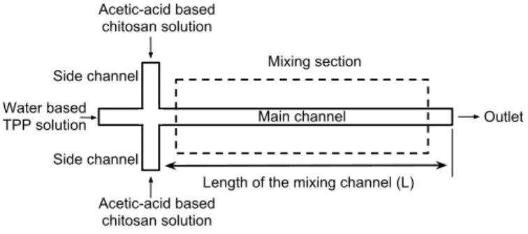
Figure 1. THE SCHEMATIC DRAWING OF THE MICROCHANNEL NETWORK
reservoirs, single exit reservoir. Micro obstacle structures as proposed in [9] are introduced within the microchannels to in-crease the mixing efficiency. In the simulations, only 2D models are considered and the mixing efficiency of several configura-tions are compared. As a result, a 3D design for a microfluidics platform which includes four channel each of which performs the synthesis in parallel is proposed and a fabrication procedure based on micromachining is introduced. The experimentation procedure is also discussed to address future research direction.
ANALYSIS
A microfluidics channel network with 3 inlet reservoirs and 1 exit reservoir is proposed for the synthesis of chitosan nanopar-ticles as shown in Fig. 1. Following the well-known ionic gela-tion method, the synthesis requires dropwise mixing of acetic acid based chitosan polymer solution with the water based TPP solution with a certain ratio. In a typical ionic gelation chi-tosan nanoparticle synthesis, mixing ratio of TPP:chichi-tosan ra-tio varies in between 1:2 to 1:5. In this study, rara-tio of 1:3 is chosen. In a typical protocol, 1% 100 mL acetic acid solution is prepared and 0.5 gr chitosan (low molecular weight, degree of deacetylation 80% ) is dissolved in this solution. Separately, 0.5% (weight/volume) TPP solution is prepared. Then, 2 mL of TPP solution is added to 6 mL chitosan solution in 10 mins time in a dropwise manner. To ensure the same order of magnitude throughput, the volumetric flow rate of the acetic acid and water solutions are taken as 0.15 mL/min and 0.05 mL/min. the width and height of the main channel and the side channels are taken as 1000 µm, and 500 µm respectively. To evaluate the mixing efficiency of the microchannel network, flow and concentration fields needs to be determined. In this model, following assump-tions are used:
(1) the working fluids are incompressible, Newtonian liquids, (2) the gravitational effects and buoyancy effects are negligible, (3) both species have identical diffusion coefficients,
the channel wall and no chemical reactions take place. (5) the mixing of two liquids ensures the mixing of chitosan
nanoparticles with TPP.
The flow field is governed by Navier-Stokes equation,
ρmu · ∇u = −∇P + µ∇2u (1)
subjected to the no-slip boundary conditions at the channel walls, specified flow rates at the reservoirs and zero pressure bound-ary condition at the exit. The concentration field is governed by convection-diffusion equation,
u · ∇c = D∇2c (2)
subjected to insulated boundary at the channel walls and the specified concentration at the reservoirs. In here, c represents the dimensionless mole fraction of the acetic acid. Therefore, c is assigned as unity at the inlets of acetic acid, and assigned as zero for the inlets of water. At the exit, convective flux boundary condition is assigned.
In these equations, mixture density and mixture viscosity need to be described in terms of the concentration. The mixture density can be determined by using the following relation [10]:
ρ = Ao+ A1T+ A2T2+ A3T3 Ao= 534.613 + 1950.54c − 1054.32c2+ 174.019c3 A1= 4.1946 − 10.5253c + 3.15922c2 A2= −0.0113495 + 0.0212374c − 0.0036607c2 A3= 8.43584 × 10⁻⁶− 1.47636 × 10⁻⁵c (3)
To determine the mixture viscosity, following relation which re-lates the water-acetic acid mixture as a function of mole fraction of acetic acid is used [11]:
ln µ = Bo+ B1/T + B2ln T + B3P Bo = −9.84679 + 5.93224c − 0.0724913c2+ 1.59018c3 B1 = 2361.48 + 202.364c − 1594.8c2 B2 = 0.00609668 − 0.00856923c B3 = 0.014739 (4)
The lowest temperature was given in [11] was 313 K, so the same temperature is used in this study. The pressure value is taken as 100 kPa, since the typical pressure drops in liquid microfluidic applications are in the order of 100 Pa [9], the variation of vis-cosity with pressure is neglected.
In order to quantify the mixing performance, the mixing ef-ficiency at the exit of the mixing section is determined. Mixing efficiency can be determined as [12],
ηm= 1 − Z A |c − c∞|dA Z A |co− c∞|dA , (5)
where c is the sample concentration, and coand c∞(= 0.75) are the sample concentrations in the completely unmixed and com-pletely mixed conditions, respectively. Therefore, ηm= 0 indi-cates a completely unmixed state, and ηm= 1.0 indicates com-plete mixing.
NUMERICAL MODELING
Commercial analysis software, COMSOL Multiphysics ,R which is based on the finite element method, was used to deter-mine the flow and concentration fields. Since the density and the viscosity of the fluid depend on the concentration of the acetic acid, and the velocities in x− and y−directions are required to determine the convective terms in the convection-diffusion equa-tion, the flow field and concentration field are coupled. Because the problem is nonlinear, stationary and nonlinear choices were used as solver parameter. Since the equations are coupled and nonlinear, it was observed that the convergence of the solution sensitive to initial guess. Therefore, to obtain the converged so-lution, the equations are solved in sequence by updating the ini-tial guess from the previous run. First, the Convection-Diffusion module is solved based on the initial zero velocities (i.e. purely diffusion equation). After that the Incompressible Navier-Stokes module together with the results that are obtained from the diffu-sion equation is computed. Then, the convection-diffudiffu-sion equa-tion resolved with the obtained velocity field. One more itera-tion was performed for both flow field and concentraitera-tion field to obtain the converged solution. The simulations were per-formed on a HP Z400 Workstation (Intel Xeon W3550, Quad
!"##$%& !###$%& !###$%& !"##$%& ' ( ( ( ( ( ( )##$%& )##$%& )##$%& *"+ ,##$%& )##$%&
Figure 2. DRAWING OF THE MICROCHANNEL NETWORK WITH OB-STACLES
Table 1. INPUT PARAMETERS FOR THE SIMULATIONS
Density of water ρw= 1000 kg/m3
Density of acetic acid ρa= 1050 kg/m3
Binary diffusion coefficient D= 10−9m2/s
L 1, 2, 3, 4, 5 cm
core, 3.06GHz, 16GB RAM). Mesh independence was checked, and during the mesh generation step maximum mesh size of 60 µm with a n element growth rate of 1.1 were specified. The mixing efficiency of each configuration was determined based on the concentration profile at the channel exit. To determine the case for completely unmixed state (co), the simulation is per-formed with very small diffusion coefficient.
RESULTS AND DISCUSSION
Two microchannel structures, one of which is a straight channel (see Fig. 1) and one of which is a channel with obsta-cles (see Fig. 2) are simulated. The parameters used in the sim-ulation are tabulated in Tab. 1. Binary diffusion coefficient is
(a)
(b)
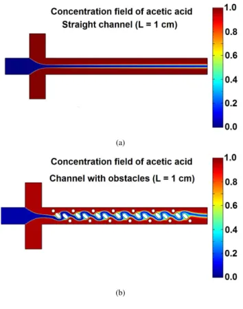
Figure 3. CONCENTRATION FIELD
taken as 1 × 10⁻⁹m2/s which a typical value for aqueous solu-tions [9]. Fig. 3 shows the concentration field for straight chan-nel and chanchan-nel with obstacles with a length of 1 cm. As seen from the figure, the channel with obstacles has a better mixing than that of a straight channel for a given length. Another impor-tant observation is that, for straight channel concentration profile symmetric around the center; however, for the channels with ob-stacles the symmetry is broken for some cases which due to the presence of the asymmetric obstacles within the microchannel.
For a better mixing efficiency, length of the mixing channel (L) is an important parameter. Therefore, microchannel geome-tries with different mixing channel length (L = 1, 2, 3, 4, 5 cm) are simulated. The concentration profile of acetic acid at the exit of the microchannel are given in Fig. 4. As the obstacles are intro-duced, and the concentration profile improves from completely
0 0.2 0.4 0.6 0.8 1.0 0 0.25 0.50 0.75 1.0 y [mm]
Concentration of acetic acid (c)
L: 10 mm L: 20 mm L: 30 mm L: 40 mm L: 50 mm completely unmixed completely mixed (a) 0 0.2 0.4 0.6 0.8 1.0 0 0.25 0.50 0.75 1.0 y [mm]
Concentration of acetic acid (c)
L: 10 mm L: 20 mm L: 30 mm L: 40 mm L: 50 mm completely mixed completely unmixed (b)
Figure 4. CONCENTRATION OF ACETIC ACID AT THE EXIT OF THE CHANNEL
1 2 3 4 5 0.2 0.3 0.4 0.5 0.6 L [cm] η m Straight channel Channel with obstical
Figure 5. MIXING EFFICIENCY FOR DIFFERENT CHANNEL CONFIGURATION
unmixed condition to completely mixed condition. To quantify the performance of mixing, the corresponding mixing efficien-cies are also illustrated in Fig. 5 as a function of length of the mixing channel. As seen from the figures, the mixing efficiency improves as the obstacles are introduced and as the length of the mixing channel increases.
Following these results, an S-shaped microchannel with ob-stacles is considered. S-shape channel geometry enhances mix-ing due the presence of the inertia in radial direction, and is more compact compared to the previous configurations. The technical drawing of the S-shaped microchannel is shown in Fig. 6. The same configuration is also proposed with a longer mixing chan-nel geometry. The concentration fields for two different S-shaped microchannels are illustrated in Fig. 7. As seen from the figure, long S-shape channel has a superior mixing performance
com-Figure 6. DRAWING OF THE S-SHAPED MICROCHANNEL
Table 2. ηm FOR DIFFERENT CHANNEL CONFIGURATIONS
Channel L [cm]
Configuration 1.0 2.0 3.0 4.0 5.0 7.0
Straight 0.210 0.299 0.335 0.380 0.421 –
W/ obstacles 0.242 0.331 0.401 0.463 0.517 –
S-shape – – – 0.492 – 0.685
pared to other configurations. Mixing efficiency values of all the configurations considered in this study are tabulated in Tab. 2. As seen form the table, long S-shape channel with a relatively compact design has a mixing efficiency of approximately 70% which is an acceptable limit for most of the mixing applications. Since S-shape channel has an enhanced performance, a mi-crofluidics platform which consists of four S-shape microchannel configuration in parallel with 4 inlet ports for acetic acid based chitosan solution, single inlet port for water based TPP solution and two outlet ports for the solution with sythentized nanoparti-cles is proposed. The CAD drawing of the proposed system can be seen in Fig. 8.
(a)
(b)
!"#$%&'()%&*()&+,%$)& -,.$/&011&.(#2%3(" 42%#$%&)$.$)5(3). !"#$%&'()%&*()&,6$%36&,63/& -,.$/&673%(.,"&.(#2%3(" 836)(67,""$#& "$%+()9 :2,)%;&+,*$) 1<8= 1#,.%36& %2-3">
Figure 8. CAD DRAWING OF THE MICROFLUIDC DEVICE
SUMMARY AND FUTURE WORKS
In this study, the mixing of acetic acid based chitosan solu-tion and water based TPP solusolu-tion is simulated by using COM-SOL Multiphysics simulation environment. The mixing ef-R ficiency of different channel configurations and geometries are analyzed. For this study, only passive mixers are considered and proposed. The proposed microfluidic system will have the poten-tial to be used for the synthesis of chitosan nanoparticles which are the key ingredients for many drug delivery systems, and will have advantages over the conventional batchwise system consid-ering the continuous flow nature which will reduce the aggre-gation of the synthesized nanoparticles. In the experimentation phase, the flow of the solutions will be driven by syringe pumps with high accuracy, and controlled by computer which will en-hance the reproducibility and the automation of the process. The products collected at the outlet of the channels will be character-ized with zeta-sizer and scanning electron microscope to verify the nanoparticle synthesis and to determine the size distribution and zeta potential of the nanoparticles. The quality of the syn-thesis process performed within microfluidic device is compared with that of the conventional, bench-top equipments. Although only passive mixers are considered in this study, in the experi-mentation phase, active mixers like pulsating flow at the channel inlet [12] or ultrasonic mixer [6] may also be considered for even better performance.
Since the dimensions of the microchannel are in millimeter range and the size of the proposed obstacle structures are around 200 µm, for the fabrications of the microchannel network, the micromachining facility of the Bilkent University Micro System
Design and Manufacturing Center will be used. Either an alu-minum mold will be micro-machined and the microchannel net-work will be fabricated out of PDMS or the channel structure will directly be micro-machined on a plexiglass substrate. De-pending on the limitations on the fabrication, full 3D geometry will be determined and 3D simulations will be performed for the proposed geometry before the experimentation phase.
ACKNOWLEDGMENT
The authors gratefully acknowledge financial support for Mr. Serdar Taze by Bilkent University Mechanical Engineering Department.
REFERENCES
[1] Muzzarelli, R. A. A., 2011. “Biomedical exploitation of chitin and chitosan via mechano-chemical disassembly, electrospinning, dissolution in imidazolium ionic liquids, and supercritical drying”. Marine Drugs, 9, pp. 1510– 1533.
[2] Mahapatro, A., and Singh, D. K., 2011. “Biodegradable nanoparticles are excellent vehicle for site directed in-vivo delivery of drugs and vaccines”. J. Nanobiotechnology, 9(55), pp. 1–11.
[3] Dai, T., Tanaka, M., Huang, Y.-Y., and Hamblin, M. R., 2011. “Chitosan preparations for wounds and burns: an-timicrobial and wound-healing effects”. Expert Rev Anti Infect Ther., 9(7), pp. 857–879.
[4] Venkatesan, J., and Kim, S.-K., 2010. “Chitosan compos-ites for bone tissue engineering–An overview”. Marine Drugs, 8, pp. 2252–2266.
[5] Grenha, A., 2012. “Chitosan nanoparticles: a survey of preparation methods”. Journal of Drug Targeting, 20(4), pp. 291–300.
[6] Suh, Y. K., and Kang, S., 2010. “A review on mixing in microfluidics”. Micromachines, 1(3), pp. 82–111.
[7] Mengeaud, V., Josserand, J., and Girault, H. H., 2002. “Mixing processes in a zigzag microchannel: Finite ele-ment simulations and optical study”. Analytical Chem-istry(16), pp. 4279–4286.
[8] Liu, Y., Kim, B., and Sung, H., 2004. “Two-fluid mixing in a microchannel”. International Journal of Heat and Fluid Flow, 25, pp. 986–995.
[9] lA. A. S. Bhagat, and Papautsky, I., 2008. “Enhancing par-ticle dispersion in a passive planar micromixer using rect-angular obstacles”. J. Micromech. Microeng., 18, pp. 1–9. [10] Sun, T., Ly, D., and Teja, A. S., 1995. “Densities of acetic acid + water mixtures at high temperatures and concentra-tions”. Ind. Eng. Chem. Res., 34, pp. 1327–1331.
[11] Qiao, Y., Di, Z. G., Ma, Y. G., Ma, P. S., and Xia, S. Q., 2010. “Viscosities of pure water, acetic acid + water, and
p-xylene + acetic acid + water at different temperature and pressure”. Chinese Journal of Chemical Engineering, 18(3), pp. 446–454.
[12] Chen, C.-K., and Cho, C.-C., 2008. “A combined ac-tive/passive scheme for enhancing the mixing efficiency of microfluidic devices”. Chemical Engineering Science, 63, pp. 3081–3087.