DEVELOPMENT OF HIGH POWER CW
YB-DOPED FIBER LASER SYSTEM
A THESIS SUBMITTED TO
THE GRADUATE SCHOOL OF ENGINEERING AND SCIENCE OF BILKENT UNIVERSITY
IN PARTIAL FULFILLMENT OF THE REQUIREMENTS FOR THE DEGREE OF
MASTER OF SCIENCE IN
MATERIALS SCIENCE AND NANOTECHNOLOGY
By Elif Gül Özkan
ii
DEVELOPMENT OF HIGH POWER CW YB-DOPED FIBER LASER SYSTEM
By Elif Gül Özkan January, 2015
We certify that we have read this thesis and that in our opinion it is fully adequate, in scope and in quality, as a thesis for the degree of Master of Science.
Assist. Prof. Dr. Bülend Ortaç (Supervisor)
Prof. Dr. Mehmet Bayındır
Assoc. Prof. Dr. Hakan Altan
Approved for the Graduate School of Engineering and Science:
Prof. Dr. Levent Onural Director of Graduate School
iii
ABSTRACT
DEVELOPMENT OF HIGH POWER CW YB-DOPED FIBER LASER SYSTEM
Elif Gül Özkan
M.S. in Materials Science and Nanotechnology
Supervisor: Assist. Prof. Dr. Bülend Ortaç
January, 2015
High-average-power fiber lasers are interesting for many applications, including scientific instrumentation, industrial material processing, imaging, medical and military technologies. Fiber concept has well established them as a very attractive beam delivery system and gain medium for laser applications. Rare-earth-doped fibers are one of the most promising solid-state laser concepts for efficient diode-pumped high power continuous wave laser systems. In fiber laser systems, the new generation fiber optical cables are used. Fiber laser systems are preferred due to the ease of usage in the field, high beam quality, low cost and low thermo-optic problems. Fiber laser system has an active medium where the light is amplified all along the fiber. The long active medium leads to reduced heat problems, high absorption rate of the light, high quality beam and less need for optimization of the cavity. We designed and developed a high power fiber laser system for metal processing. Material drilling and cutting, which are significant processes in industry, are performed with the powerful fiber laser systems. The main purpose of this thesis is to develop a laser system which enables fast and accurate cutting process with impressive properties such as compactness, low maintenance problems and so on. The fiber laser resonator was first numerically studied by using software and then various laser parameters and laser architectures were designed. In order to perform the numerical results, we designed a compact high power all-fiber laser cavity. In real world applications, the use of free space components to constitute the cavity
iv
leads to environmental instabilities and power loss, which results in a decrease of the fiber laser efficiency. One of the most important advantages of all fiber laser system is to handle environmental factors such as humidity, vibrations. To achieve high power level from the fiber laser systems, it is significant to use powerful pumping systems (high power diode lasers), passive laser cavity components (combiner, FBG) and also double-clad active fiber that operate at high power level. In this study, we used new generation laser cavity components. The pump sources have been analyzed in terms of power and wavelength stabilities. Also, experiments have been performed to keep pump sources at optimum temperature to obtain accurate wavelength to excite ytterbium atoms located in the active media. In order to constitute high power laser system, we integrated all fiber optic components for efficient operation. The laser has stable continuous wave regime in temporal domain due to the cavity design. The output power of the system is about 548 W. The M2 value of the system is less than < 1.7. The operation wavelength of the fiber laser was stabilized with FBG at 1.08 µm. We also demonstrate the capability of our fiber laser system for material processing. We successfully drilled and cut 1.7 mm thickness steel target with lower output power of fiber laser (100 W).
Keywords
Fibers, Lasers, High-Power Laser Systems, Powerful Fiber Laser Components, Material Processing with Laser
v
ÖZET
YÜKSEK GÜÇLÜ DOĞRUSAL ĠTERBĠYUM KATKILI FĠBER LAZER SĠSTEMĠ
Elif Gül Özkan
Malzeme Bilimi ve Nanoteknoloji Yüksek Lisans
Tez Yöneticisi: Yard. Doç. Prof. Dr. Bülend Ortaç
Ocak, 2015
Yüksek güçlü fiber lazerler bilimsel araçlar, endüstriyel malzeme iĢleme, görüntüleme, medical ve askeri alanlar gibi pek çok uygulama açısından önem taĢırlar. Fiber lazerler lazer uygulamaları için sinyal kazanım ortamı ve ıĢık iletim sistemi açısından iyi kurulmuĢ konseptir. Nadir element katkılı fiberler, katı hal lazer konspti içerisinde verimli diyot pompalama, yüksek güçlü ve devamlı dalga açısından geleceği en parlak olan konsepttir. Fiber lazer sistemlerinde, yeni jenerasyon fiberler kullanılmaktadır. Fiber lazer sistemleri, alanda kolay kullanımı, yüksek ıĢık kalitesi, düĢük maliyet ve düĢük termo-optik problemler açısından tercih edilmektedirler. Fiber lazer sisteminde bulunan aktif ortam ile ıĢık ortam boyunca yükseltilir. Uzun aktif ortam sayesinde ısınma problemi azaltılır, ıĢığın yüksek oranda absorbsiyonu, yüksek ıĢık kalitesi sağlanır ve kavitenin optimizasyon ihtiyacı azaltılır. Metal iĢleme için yüksek güçlü fiber lazer sisteminin dizaynını ve geliĢtirilmesini yaptık. Endüstride önemli bir iĢlem olan malzeme delimi ve kesimi güçlü fiber lazerler ile gerçekleĢtirilmektedir. Bu tezin ana amacı, hızlı ve doğru kesim iĢlemeyi örneğin; kompakt, düĢük bakım ihtiyacı ve benzeri açılardan üstün özellikler ile
vi
gerçekleĢtiren fiber lazer sistemi geliĢtirmektir. Fiber lazer rezonatörü öncelikle numeric olarak yazılım yardımı ile çalıĢılmıĢ ve sonra değiĢik lazer parametreleri ve lazer mimariliği ile dizayn edilmiĢtir. Numerik çıktıları gerçekleĢtirebilmek için, yüksek güçlü tamamı ile fiberden oluĢan lazer kavite oluĢturulmuĢtur. Gerçek uygulamalarda, kaviteyi oluĢturmak için kullanılan, açık uzay komponentleri, çevresel dengesizliklere, güç kaybına ve bu etkenlerde fiber lazerin verimliliğinde düĢüĢe yol açmaktadırlar. Tamamı fiberden oluĢan lazer sistemlerinin en önemli avatajlarından biride nem titreĢim gibi çevresel faktörlerin üstesinden gelebilmesidir. Güçlü pomplama sistemleri (yüksek güçlü diyot lazerler), pasif lazer kavite komponentleri (kombiner, FBG) ve ayrıca yüksek güç seviyelerinde çalıĢan çift kabuklu aktif fiberler kullanmak, fiber lazer sistemlerinden yüksek güç seviyesine çıkabilmek için,büyük önem taĢırlar. Bu çalıĢmada, yeni jenerasyon lazer kavite komponentleri kullnılmıĢtır. Pompalama kaynakları gü. Ve dalga boyu stabiliteleri açısından analiz edilmiĢtir. Ayrıca, aktif ortamda bulunan ittebiyum atomlarını doğru dalga boyunda uyarabilmek için, pompalama kaynağının optimum sıcaklığı ile ilgili çaılĢmalar gerçekleĢtirilmiĢtir. Yüksek güçlü fiber lazer sisteminde, tamamı fiberden oluĢan komponentler verimli çalıĢma için entegre edilmiĢtir. Elde edilen lazer sistemi kavite dizaynından dolayı, zamansal alanda stabil devamlı dalga boyu sahiptir. Sistemin çıkıĢ gücü 547 W’ tır. Sistemin M2 değeri 1.7’ den düĢüktür. Sistemin çıkıĢ dalga boyu 1.08 µm de FBG ile stabildir. Ayrıca geliĢtirdiğimiz fiber lazer sisteminin malzeme kesimi için uygun olduğunu göstermiĢ bulunmaktayız. 1.7 mm kalınlığına sahip çelik hedefleri baĢarılı bir Ģekilde fiber lazerin çıkıĢ gücü ile kesilip delmiĢ bulunmaktayız (100W).
Anahtar Kelimeler
Fiberler, Lazerler, Yüksek Güçlü Lazer Sistemleri, Güçlü Fiber Lazer Komponentleri, Lazerle Malzeme ĠĢleme
vii
Acknowledgments
This thesis work has been carried out in the Fiber Laser research group of theDepartment of Materials Science and Nanotechnology at Bilkent University. I would like to thank my advisor Bülend Ortaç, for giving me the opportunity to work on this project. I also thank him for his valuable guidance and support. This thesis would not be possible without his patience and encouragement. My special thanks to my group friendsCanan KurĢungöz, Yakup Midilli, Bartu ġimĢek, Elif Uzcengiz, BüĢra Öz, Fehmiye KeleĢ,for their good friendship,generous help, useful discussion and mostly for their laughter.
I also would like to thank the Ministry of Science, Industry and Technology for their support in this project.
I also thank to ERMAKSAN Metal Fabricating Machinery for material, moral and financial support.
I also would like to thank UNAM staff for their help and understanding.
The immeasurable thanks go to my parents for their deepest love, support and sacrifice. I really appreciate every single piece of it. You always back me up whenever I need help.
viii
Table of Content
Acknowledgments ... vii
List of Figures ... x
List of Tables ... xii
Chapter 1 ... 1
1.1 Introduction ... 1
1.1.1 Fiber Laser Technology ... 5
1.1.2 Principles of Fiber Laser ... 6
1.1.3 Application Areas of Fiber Lasers ... 8
1.2 Fiber Technology ... 9
1.2.1 Double-clad fibers ... 11
1.2.2 Large mode-area fibers ... 14
1.2.3 Attenuation in fibers ... 16
1.2.4 Nonlinear effects ... 17
1.2.5 Ytterbium-doped gain media ... 19
1.2.6 Electronic level structure of Yb3+ ions ... 19
1.2.7 Spectroscopic analysis of Yb doped fibers ... 22
1.3 Modelling of fiber laser resonator ... 23
Chapter 2 ... 28
Experiments ... 28
2.1 Fiber laser design ... 28
2.2 Characterization of equipments ... 37
ix
2.4 Material processing of fiber laser ... 49
Conclusion ... 51
Discussion ... 52
x
List of Figures
Figure 1. 1: Evoluion of the average output power of fiber lasers ... 5
Figure 1. 2: Scheme of absorbtion, spontaneous emission, stimulated emission . 7 Figure 1. 3: Schematic of all fiber laser system ... 8
Figure 1. 4: Refraction of light, Critical angle, Total internal reflection ... 10
Figure 1. 5: Refractive index profile of double clad fibers ... 12
Figure 1. 6: Light guidance in the cladding pumped double-clad fiber ... 13
Figure 1. 7: Different fiber inner cladding and core geometries. ... 13
Figure 1. 8: Light absorption of different type of double clad fibers ... 14
Figure 1. 9 :Bending loss for SM, SI and LMA fibers ... 15
Figure 1. 10: Energy level diagrams of different laser systems ... 20
Figure 1. 11: Absorption and emission cross-sections of Yb-doped fibers ... 22
Figure 1. 12: Scheme of two level laser ... 23
Figure 1. 13: Schematic of pumped fiber laser cavity ... 26
Figure 2. 1: Cavity design of fiber laser with RP simulation ... 30
Figure 2. 2: RP simulation of power vs position. ... 31
Figure 2. 3: Schematic of fiber laser resonator ... 31
Figure 2. 4: Splice processes ... 32
Figure 2. 5: The output power of all diodes. ... 33
Figure 2. 6: Splicing process between diode fibers and combiner fibers ... 33
Figure 2. 7: The output power of diodes after splicing with combiner ... 34
Figure 2. 8: Design of the cooling plate for combiner ... 34
Figure 2. 9: The cooling plate for combiner ... 35
Figure 2. 10: Splicing process between combiner and FBG fiber. ... 35
Figure 2. 11: The cross section images of fibers ... 36
Figure 2. 12: The splicing process between FBG fiber and the active fiber ... 36
Figure 2. 13: Splice operation between FBG and active fiber ... 37
Figure 2. 14: Connections between drivers and diodes ... 38
xi
Figure 2. 16: Integration of diodes and cooling units ... 39
Figure 2. 17: Stripped fiber before cleaving ... 40
Figure 2. 18: a) Poor cleaving process ... 41
Figure 2. 19: a) Diode 1 b) Power of diode 1 ... 42
Figure 2. 20: a) Power of diode 1 b) Optical spectrum of diode 1 ... 42
Figure 2. 21 : The scheme of cooled diodes in group ... 43
Figure 2. 22: Optical spectrum of all diodes ... 44
Figure 2. 23: M2 data of fiber laser resonator M2x is 1,6 and M2y ... 45
Figure 2. 24: Temporal image of fiber laser resonator ... 45
Figure 2. 25: The optical spectrum of fiber laser resonator at 100 W ... 46
Figure 2. 26: The optical spectrum of fiber laser resonator at 200 W ... 46
Figure 2. 27: The optical spectrum of fiber laser resonator at 300 W ... 47
Figure 2. 28: The optical spectrum of fiber laser resonator at 547 W ... 47
Figure 2. 29: Optic spectrums of fiber laser ... 48
Figure 2. 30: The output power of the fiber laser resonator ... 49
Figure 2. 31: Experimental setup for material cutting and drilling ... 50
Figure 2. 32: Optical microscope image of drilled steel ... 50
xii
List of Tables
Table 2. 1: The parameters for different type of fiber laser resonator ... 29 Table 2. 2: Parameters used for diodes ... 41 Table 2. 3: Power of diodes ... 42
1
Chapter 1
1.1 Introduction
Stimulated emission is an quantum mechanical phenomena which was discovered by Albert Eisntein in 1917 [1] and the idea of laser concept is realized. Since then, various type of lasers have been developed. As a gain media, there are many type of metarials such as solid state materials, gases, liquids. Also, laser transitions of many type of elements have been demonstrated.To achieve high power laser operation with high brigthness can be obtained efficiently by using diode pumped rare earth solid state lasers technology [2]. The first semiconductor laser was developed by Robert N. Hall
et al., in 1962 [3]. The kW regimes have been achieved by the new diode
systems such as stack and bars.
In classic solid state lasers gain media is a rod hence when this media is pumped, there is a temperature increase in the center of the rod. This stiuation leads to limitation in power scaling and obtaining good beam quality. Therefore different shape of gain medias have been invented such as slab [4] or fiber designs [5].Snitzer et al., proposed the use of fibers as an active medium in 1961. They used small fibers as a mode selector for masers. Fibers have a maser material core, surrounded by cladding which has lower refractive index when compared to core. They investigated similarities of the cavity with Fabry‐Perot interferometer. Because of the stronger mode coupling and mode selection, they used these principle advantages. In this study, core was small enough to carry only HE11 modes. During this study, they encountered with difficulties such as
pumping the light into small volume of fiber [6]. One of the most up and coming type of solid state laser system is rare-earth doped fiber laser system.
2
In 1964, the first operating Neodymium fiber laser was demonstrated at Bell Labs by J. E. Geusic, H. M. Marcus and L. G. Van Uitert [7]. Due to the preferred properties of yttrium aluminum garnet doped with trivalent Neodymium such as optical isotropy, hardness, and stability, it was used as the gain medium and system was pumped at room temperature with tungsten lamp. The emitting light was near infrared which was 1064 nm. They used multilayer dielectric reflectors at 99% at 1.06 µm.
The inadequacy to couple high power pumps into the single clad fibers leads to failure in the system. The first developed double clad fibers was demonstrated in 1974. In this concept, core of the fiber was covered with a lower refractive index material. Hence light can be guided in the inner cladding. This concept is used for active fibers to couple the high power low beam quality diode fibers so that this limitation was overcame [8].
In 1988, Hanna et al. showed ytterbium doped (YDFL) fiber laser which had wide turning range between 1.015µm and 1.40µm when they pumped by a dye laser at 840 nm [9]. Developments in the area of lasers are in progress since then.
In 1999, Dominic et al. demonstrated 110 W fiber laser. In this study they used Yb doped fiber which had a rectangular inner cladding. They pumped the system at 915 nm wavelength with diode bars. The total input power was 180 W. They used dichroic mirror, which was used high reflective mirror, to couple the light into the fiber and fiber and was polished so that they obtained laser output coupler. They obtained 110 W output power at 1120 nm wavelength [10].
In 2004, Barannikov et al. presented 250W single-mode linearly-polarized Yb doped fiber laser. Their system consisted of two stages. First one was master oscillator. To achieve linear polarization they used polarizer in the laser cavity. Also to couple the light they used mirror which had 99% of reflectivity. First
3
stage emitted 90 W pump power. The second one was booster amplifier and they used 14 m panda type fiber. The system was pumped 450 W and the output signal was at 1076 nm wavelength. The M2 of the system was < 1.04 [11].
In 2004, Khitrov et al. showed 306W all-fiber linearly polarized Yb fiber laser. They used polarization maintained (PM) large mode area (LMA) Yb doped fiber which was 33 m long. They used FBG with > 99% reflectivity. On the other end of the fiber was cleaved which provided 3.5% Fresnel reflectivity. They coiled the fiber to eliminate transverse modes. The system was pumped at 915, 940, 976 nm wavelengths and total pump power was 496 W. The output signal of the laser was 1086 nm wavelength [12].
In 2004 Jeong et al. demonstrated Yb doped 610 W fiber laser. They used Yb doped fiber as an active medium. The fiber had D shape to increase the cladding mode to overlap with the Yb doped core which was 9 m long. The pump wavelength was at 972 nm. The pump power of the system was 760 W. The cavity was obtained by using high reflectivity dichroic mirror at 1.1µm and the other end of the fiber has 4% reflecting face. The obtained the laser centered at 1090. The laser spectrum was between at 1070 and 1100 nm [13].
In 2004, Jeong et al. developed a Ytterbium-doped fiber laser with 1.36 kW output power and cw regime. The output wavelength was 1100 nm and the slope efficiency of the laser was 83%. They pumped the system at 975 nm wavelength with diode stacks and the total pump power was 1.8 kW. Their active medium was D-shaped inner cladding. Their beam quality M2 was 1.4. They used dichroic mirrors to couple the pump light into the fiber and the fiber end cleaved perpendicularly which leaded to 4% reflectivity. In order to achieve these parameters we can increase the pump power, change the fiber type [14]. Also this design can be improved by using FBGs to avoid the free space losses.
4
The new generation of active fiber results the increase of the fiber laser output. The long interaction path of the light in the active medium permits very large gains. Furthermore, due to single mode light, high beam quality is obtained which is not connected with the output power of the fiber laser. Also, using fiber based reflectors which are known as fiber bragg garting (FBG), combiner leads to avoid alignments and free space components. Moreover, heat can be dissipated due to the large surface-to-active-volume ratio of active fibers. These are the main reasons of power handling property of fibers. To use rare-earth materials advances these properties. The most attractive one is the yterbium which has a very close signal wavelength compared to pumping wavelengths.On the other hand, power scaling results in some phenomena such as nonlinear effects and thermal problems in fibers. The new generation of large mode area fiber is overcome this issue at certain level. Theoretical studies have also become crucially important in order to fully understand those parameters and to design efficient fiber devices and systems [15].
The motivation of this thesis is to develop 500 W fiber laser resonator for metal processing.The fiber laser resonator was firstly numerically simulated by using software and various parameters which are studied in simulations. In order to do the simulation, we designed the fiber laser cavity architecture. In order to achieve high powers, it is vital to increase the pump power of the system. Also fibers which is used in the system should handle high power and temperature. So in this study we used new generation fibers to overcome thermal problems. Moreover, as it is explained in the literature using the free space components to constitute the cavity causes power loss which leads to decreasing of the fiber laser efficiency. Therefore we used fiber based components. Instead of using dichroic mirrors we used FBGs in our system. Also high power combiner was used to couple the light in to the fiber rather than using lenses and mirrors so that we avoid power losses and thermal problems. One of the most important advantage of the all fiber laser system is that it does not suffer from environmental factors such as humidity, vibrations.In this study, pump sources
5
have been analyzed in terms of power and wavelength. Also,experiments have been performed to keep pump sources at optimum temperature to obtain accuratewavelength to excite ytterbium atoms. The fiber laser is operating in the continuous wave regimedue to cavity design. The fiber laser was cavity established with FBGs and the active fibers. The output power of the system is 547 W. The M2 of the system is < 1.7. The laser has continuous wave regime in temporal domain. The output wavelength of the fiber laser was 1.08 µm. We tested our fiber laser system for cutting and drilling process. We demonstrated the cut and drill results on steel material.
1.1.1 Fiber Laser Technology
Fiber lasers are different than standard solid state lasers in terms of gain medium being rod, slab or disk. From the central core of the fiber, laser light is emitted. Due to the fact that fiber has a large surface to volume ratio, heat can be dissipated relatively easier than other type of lasers [16]. Fiber lasers are optically pumped usually with diodes. Fiber laser systems are usually composed of fiber components most of which are fiber-coupled to one to another.
6
Fiber laser systems are known with high beam qualities and high average output powers. These properties of fiber laser systems have wide range area ranging from to industrial military to scientific applications. In the last two decades, the power of the continuous wave, diffraction limited fiber lasers is increasing. Between in 1990 and 2000 the output power was more than 100 W. After 2000 fiber laser systems have reached kW ranges. In 2009 the output power was 10 kW. The evolution of the average output power of fiber lasers is shown in fig. 1.1 [15].
All fiber laser systems has many advantages such as, low thermo-optical problems, high quality and efficient laser light, environmental stability, compactness, low cost. Fiber laser systems, with the ease of use provided by the field, are preferred especially for high-power laser systems because of reduced heating problem, higher productivity level for increased rate of absorption of the pumped light, and high-quality optical cavity laser light produced during the use and optimization of the system [17].
1.1.2 Principles of Fiber Laser
The word laser corresponds to Light Amplification by the Stimulated Emission of Radiation. Stimulated emission is a quantum mechanical phenomenon which is discovered by Einstein in 1917 [1].It is possible to create an emission by stimulating an electron with electromagnetic field which is already found in the upper energy state. When electrons absorb second photons, the emitting light is in same direction with the incoming photon. All of the irradiated photons are in the same phase, frequency, polarization and direction. Coherent light is obtained by stimulated emission [18].
Due to light-matter interaction three physical phenomena occurs; absorption, spontaneous emission, and stimulated emission. A simplified scheme of these
7
processes, when only two energy levels E1 and E2 are involved, is shown in Fig.
1.1.
Figure 1. 2: Scheme of a) absorbtion b) spontaneous emission c) stimulated emission
Electrons which are found in ground state have the energy of E1. If a photon hits
electrons with enough energy to excite them into upper energy state, this process is called as absorption. This event can lead to population inversion which is explained as when more electrons found in the excited energy state compared to lower energy state and the population inversion is the building block of the laser systems.
Excited electrons can go back to their ground state by emitting a photon randomly. This is so called spontaneous emission or luminescence which in this process the emitting photons have different phase, frequency, polarization, and direction. It can be defined as incoherent radiation [18].
A working laser is composed of resonator with gain media and pump sources which is called pump diodes or laser diodes to provide energy to electrons in the gain medium.
Pump source can bea single diode, or many separate pump diodeseach of whichhas a fibergoing into a combiner. The fiber which is doped with rare earth material is the gain medium. The cavity mirrors, which are so called fiber bragg
8
gratings, can be fabricated in the fiber.The cavity mirrors are found on each end of gain medium fiber. In fiber lasers, there are no bulk optics at the end, as long as the output beam does not go into anywhere other than a fiber. The gain medium can be long so it can be coiled according to bending ratio[2]. The result is all fiber laser system. In fig 1.2 shows the scheme of all fiber laser system.
Figure 1. 3: Schematic of all fiber laser system
A long interaction length is given by using fiber as a gain mediumwhich this situation serves very efficiently for pump diodes.High photon conversion efficiency results from this design along with durability and compactness [20]. Owing to the fact that fiber components are spliced with each other, there is no need for optics to make alignment.
1.1.3Application Areas of Fiber Lasers
In fiber laser systems, light is coupled into a flexible fiber so that it allows light to be delivered easily. Because of the fact that fiber lasers have low thermo-optical problems, high vibrational stability, extended lifetime, free maintenance, low costand high peak power, they can be used in the areas of material processing such as marking, engraving, cutting, telecommunications, spectroscopy, medicine, military and so on [21].
9
The fiber-based laser systems are highly adaptable [22]. These kind of systems can be adapted to various application areas from welding, drilling marking of metal sheets to producing femtosecond or nanosecond pulses even fiber amplifiers.
There are several new breakthroughs that build upon the unique properties of the laser. Due to fact that laser light is coherent, it forms highly order light waves. This leads to applications such as holography, astrophysics. Also laser light emits monochromatic light which means emitting ultra-pure colors. Hence the applications of this property is atomic clocks, astronomy, and metrology. Moreover, laser light has high frequency that encodes enormous amounts of information so that it is used for supercomputing, telecommunication. Furthermore laser light can be focused small spots less than 1/100 width of hair which opens the doors of application of optical data storage. One of the other important property of the laser is that laser light can have high power which means delivering the high intensities to small areas. Therefore it is used for manufacturing, cutting, welding, and surgery. Laser light can generate short pulses which are shorter than a femtosecond so that applications of this property are advancing our understanding of biology, physics, chemistry, stroboscopic pictures of atoms and molecules in action. Finally, laser light has large pulse energies. It creates pulses shorter than 10 billionths of a second with energies greater than a stick of dynamite. It can be taken advantage of the applications such as drilling, laser fusion [21].
1.2 Fiber Technology
Fiber technology depend on the basic principle of total internal reflection. Total internal reflection can be explained as a phenomenon which occurs when a propagating wave hits a medium boundary such as water or glass at an angle which is larger than normal of the surface. In order to occur total internal reflection there are two conditions;
10
1. The wave must propagate from a medium which has a high refractive index to another medium which has less refractive index.
2. The angle of the propagating wave must be larger than critical angle.
Figure 1. 4: n1 < n2 a) Refraction of light b) Critical angle c) Total internal reflection
Critical angle is the angle that the waves cannot pass through to the other medium which has lower refractive index. When a propagating wave hits a boundary between mediums, the wave can be partially reflected and partially refracted. On the other hand, when the incident wave hits a boundary with an angle larger than the critical angle, the wave is reflected and the wave cannot cross the boundary leading to a total back reflection to the internal part [23].
The optical fibers are composed of core and cladding which are highly pure solid glass. An acrylate polymer is covered the cladding to protect the fiber. This is so called coating which protects the glass dust, scratches and gives the glass durability. The coating can be easily removed from the glass by stripping in the case of fiber processing such as cleaving, splicing [24].
11
1.2.1 Double-clad fibers
Double-clad fibers are extremely important for high power fiber laser technology and amplifiers.H. Po et al. invented cladding pumping and this is one of the most important step offiber amplifiers and lasers[25]. It is possible to reach continuous power and several kilowatts by using this method. In the meantime output signal is near diffraction limited beam quality [13].
Good beam quality depends on single mode of the output of the active fiber. Pumping units have single mode core which is desirable for beam quality. However, they are limited interms of power for high power fiber laser systems. Multimode fibers can carry high power but output is poor interms of beam quality. Therefore, to obtain high beam quality, the core of the active fiber should be in single mode.
This contradiction was solved with double-clad fiber by Snitzer et al. in 1988 [26]. They studied with fibers by coupling high power multi-mode pump laser into a large inner cladding (ic) index lower than core but higher than outer cladding (oc).
12
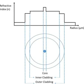
Figure 1. 5: Refractive index profile of double clad fibers
This can be expressed by ncore> nic> noc so that the guiding of the light is
maintained by total internal reflection in inner cladding and same for the core, but for a different range of wavelengths. Hence, high power diode lasers can be used as the optical pump source. The inner cladding has larger area than the core therefore has a higher numerical aperture. This leads to carrying of many propagation modes in inner cladding. Pump light is absorbed by active dopants in the core when it is coupled to active fiber. In active fiber, the pump light is amplified so that even by using low beam quality of the multimode diode laser, single mode beam quality can be obtained. In fig. 1.5 cladding pumped double clad active fiber was shown.
13
Figure 1. 6: Light guidance in the cladding pumped double-clad fiber
It is an easy process to couple the pump light into the inner cladding because of its large numerical aperture. When pump light propagates into the inner cladding, output signal propagates into the core. Because of the fact that core is doped with rare-earth material, while light propagates into the core, it stimulates atoms and amplification of light occurs [27]. It is called cladding pumping.
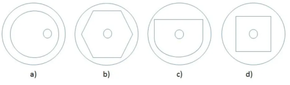
To increase the coincidence of the pump modes with core of the fiber, different inner cladding geometries were developed. In fig 1.6double clad fiber designs with non-circular inner cladding geometry were shown.
Figure 1. 7: Different fiber inner cladding and core geometries used for increasing pump absorption: (a) offset core fiber, (b) octagonal inner cladding, (c) "D" shaped inner cladding, (d) square inner cladding.
14
Figure 1. 8: Light absorption of different type of double clad fibers [2]
The disadvantage of the double-clad fibers have reduced pump light absorption. The reason of that is the intensity distributions mainly found in the inner cladding. It is not coincide with the doped core. Therefore, efficiency reduces. This situation can be overcome by altering the symmetry of the inner cladding. Geometries which are shown in fig 1.7 can avoid the undesired modes of the pump light by mode mixing. Also, another option to overcome this undesired modes is to bend the fibers periodically [2].
1.2.2 Large mode-area fibers
It is possible to maintain both diffraction limited beam quality and high output powers with double clad fibers, especially large-mode-area (LMA) DC fibers. LMA fibers support few modes so that excellent beam quality is obtained. By using single mode (SM), it is possible to obtain diffraction limited outputs.However, SM fibers cannot be used for high power applications due to their small mode area. On the other hand, multi-mode fibers (MM) can handle
15
high powers but they have poor beam quality because of the presence of many modes in them [28].
LMA fibers have reduced optical intensities so that possibility of occurring nonlinear effects decreased and damage threshold of fibers are increased. Typically, SM fibers have low effective area. On the other hand, LMA fibers have very large area than SM fibers. To eliminate nonlinear effects and damage in the fibers, the core size has to be increased [29]. Those fibers are called LMA fibers. LMA fibers supports few modes. By bending the LMA fibers, extra modes can be eliminated as it given .n fig.1.9 [30].
Figure 1. 9 :Bending loss as a function of bending radius for SM, SI and LMA fibers [30].
The dilemma is that when the core size increases, the beam quality reduces. To overcome this effect and to maintain single mode, there are several options. The most significant one of them is that numerical aperture can be decreased while increasing the core diameter, so that high powers can be achieved without nonlinear effects and damaging the fiber [21].
Recently, because of the advantages of LMA fibers, in fiber laser technology has significant increment about diffraction limited beam outputs from diode
16
laserswhich have high brightness, continuous-wave (cw). The output power of Yb-doped fiber lasers have reached tens of kilowatts in 2014 [15].
1.2.3 Attenuation in fibers
Attenuation can be explained as the reduction of intensity of light in fiber optic cables. Attenuation in fibers can be caused by optimization, fiber geometry, design of system and environmentalfactors.More specifically, it can be caused by the structure of glass such as atomic structure, point defects, fiberization process, interfacial structure of core-clad surface, and uniformity of core-clad structure.The loss of light power is expressed by decibel (dB) in optical fibers. Loss in fiber optical cable is the attenuation per 1-km length and expressed as dB/km, which is the attenuation coefficient. It is calculated by below equation 1 (eqn.1); [31]
𝛼𝑡𝑜𝑡𝑎𝑙 𝑑𝐵 𝑘𝑚 = 10 𝑙𝑜𝑔 𝑃𝑖𝑛𝑝𝑢𝑡
𝑃𝑜𝑢𝑡𝑝𝑢𝑡 (eqn. 1)
Here,Pinput is the input power of light in to the fiber; Pout is the output power of
the light; αtotal is the loss of light. To obtain total loss in fiber, the result is
multiplied with total length of fiber.There are several parameters that effects the attenuation;
1. Extrinsic parameters 2. Intrinsic parameters 3. Bending losses
4. Splice and connector losses 5. Fiber structure
6. Fiber fabrication 7. Rayleigh scattering 8. Absorption
17
1.2.4 Nonlinear effects
Nonlinearity is an optical phenomenon which is the nonlinear response to a light filed [32]. Basically, under an applied electric fieldelectrons acts in anharmonic motion. Because of the fact that the anharmonic motion electric dipoles is not linear, polarization P can be calculated with the following equation 2(eqn. 2):
𝑃 = Ɛ0𝑋(1)𝐸 + Ɛ0𝑋(2)𝐸2+ Ɛ0𝑋(3)𝐸3+ ⋯(eqn. 2)
where Ɛ0 is the permittivity of vacuum and 𝑋(𝑘)(k = 1, 2,...) is kthorder
susceptibility [33].
𝑋(1)which is the linear susceptibility makes the major contribution to 𝑃. 𝑋(2)is
the second order susceptibility which is responsible for secondharmonic generation, frequency doubling, sum and difference frequency generation, and parametric amplification. For instance, silica terminates 𝑋(2) due to asymmetric
molecule of silica [31]. Hence, second order nonlinear effects are not seen in optical fibers. On the other hand, second harmonic generation can reveal itself under certain conditions. For instance, defects in the fiber core can contribute to second harmonic generation. Finally,𝑋(3) has the minor contribution to
nonlinear effects in fibers [32].
Below,the explanations of nonlinearities in order to sum up all nonlinear effects are given;
𝑋(2)is responsible for effects such as frequency doubling, sum and difference
frequency generation, and parametric amplification[32].
𝑋(3) is responsible for the Kerr effect which increases the refractive index which
18
self-focusing, self-phase modulation, cross-phase modulation, and four-wave mixing [33].
There are two types of Raman scattering, which are linear and non-linear. Nonlinear optics based on stimulated Raman scattering. It is related to 𝑋(3)
nonlinear polarization. Raman scattering can be spontaneous and stimulated. If monochromatic light (laser) propagates in an optical fiber, spontaneous Raman scattering (SRS) happens. Some of these photons are introduced to different frequencies. Hence scattered photons can lose or gain energy. In stimulated Raman scattering, if there is linearly polarized pump light, the polarization of the scattered light can be parallel or perpendicular. In case when the photons are already within other frequencies, these photons in these frequencies can be increased. This is called stimulated Raman scattering [31].
At large intensity in an optical fiber, Brillouin scattering occurs. Because of the fact that the electric field generates stress in the core of the fiber, electrostriction is formed. It causes difference in the refractive index of the medium. The scattered pump light is called as Brillouin scattering [32].
One of the differences between Raman scattering and Brillouin scattering is that whileoptical phonons are participated in Raman scattering, acoustic phonons are participated in Brillouin scattering.Another difference is that Raman scattering can form in back and forward directions but Brillouin scattering occurs in only one direction [32].
If two photons are simultaneously absorbed, this process is called two-photon absorption. This is related to 𝑋(3) nonlinear polarization. It is usually bigger for
19
1.2.5 Ytterbium-doped gain media
The first Ytterbium-doped fiber laser was developed in 1988 by Hanna et al. [9]. Due to the fact that ytterbium-doped systems have higher excited state absorption and emission bandwidth, Yb-doped systems became popular among the other rare-earth doped fibers. Yb- doped fibers have broad wavelength range between 975 and 1200 nm which this can be considered as a very broad range [34]. Because of the fact that ytterbium ion has simpler energy level scheme compared to the other rare earth materials, it is suitable for diode pumping applications [35].Yb-doped systems also have no concentration quenching and have small thermal loading.
In 1971, Reinberg et al. used a GaAs: Si light‐emitting‐diode (LED) as a pumping unit which had 1.03 μm wavelength. They used YAG:Yb laser rod which had been constructed with the rod and they cooled it at very low temperatures. Finally, they obtained pulsed operation with a peak laser power of 0.7 W [36].
In 1991, Lacovara et al. used InGaAs diode laser as a pump unit which was 968 nm wavelength. Thermoelectric cooler was used to control the temperature. They showed that high efficiency diode-pumped operations could be possible with using more diode lasers [37].
1.2.6 Electronic level structure of Yb3+ ions
Ytterbium (Yb) is an element which is known as rare earth metal. The ytterbium ion which is Yb3+ is used as a doping material in lasers that is called active/gain medium in solid state lasers and fiber lasers [38]. In general, Yb doped lasers operate at 1.06–1.12 µm wavelength when they pumped at 900 nm – 1µm wavelength optically [35, 39].
20
The Yb3+ is a suitable ion for diode pump due to the fact that it has simpler level scheme and desirable for laser systems [35]. Yb3+has 4f13 shell which lacks one
electron compared to filled shell [35]. In Yb3+ ions, the two energy levels is comprised for light amplification which are 2F7/2and 2F5/2 with near infrared or
visible ranges. The first one is the ground level and the second one is the higher excited level [33, 35].
Due to the stark effect, these energy levels in pump and laser transitions are split into sub-energy levels. Stark effect is the splitting of atomic energy levels of radiating atoms, ions or molecules when they subjected to an exterior electric field [40]. It is shown in fig. 1.8.
Figure 1. 10: Energy level diagrams of different laser systems. Energy levels are shown as horizontal lines. The higherthe line, the higher the energy they correspond to. a) Represents three-level system as it is seen the transitions of laser ends at ground energy level. b) Represents four-level system. The transitions of the laser ends where the laser transition ends at energy level E2. c)
Represents quasi-three-level system. In thermal equilibrium, population occurs at the lower laser energy state.
There are several advantages of Yb-doped active medium. One of the most important advantage is that only one excited state level is comprised for laser transitions. Comparing to other rare earth materials Yb has smaller energy band gap between ground and excited states leading to low quantum defects. Generally, wavelength of lasing photons is higher than the pump photons which
21
meanthat energy of lasing photons is lower than that of the pump photons. It is called Stokes shift. 100% of power efficiency cannot be obtained even every pump photons transformed into laser photons. The quantum defect can be explained as the difference of photon energies which is given in equation 1.2.6(eqn. 1.2.6); [41].
𝑞 = ℎ𝜐𝑝𝑢𝑚𝑝 − ℎ𝜐𝑙𝑎𝑠𝑒𝑟 = ℎ𝜐𝑝𝑢𝑚𝑝 . 1 − ℎ 𝜐𝑙𝑎𝑠𝑒𝑟
ℎ𝜐𝑝𝑢𝑚𝑝 (eqn. 1.2.)
Yb-doped active medium has small quantum defect,in other words it has a few percent of the pump photon energy, so that Yb-doped laser devices has higher power efficiency and low heat generation. On the other hand, small quantum defect causes quasi-three-level behavior of active medium. The transitions of laser end on ground state for three level systems. The strong absorption occurs in unpumped active medium during the laser transition. The threshold pump power gets higher due to the fact that population inversion and laser gain emanates when atoms or ions are pumped into upper energy level. In quasi three level mediums, there is an intermediate level which is very close to the ground state [42]. A significant part of population in that level is presented in heat balance at the operating temperature. Hence, the unpumped active medium provokes reabsorption loss at the laser wavelength. Therefore higher pump intensities is needed for laser operations.
It can be seen that quasi-three-level or four level in Yb doped fibers can vary according to pump and seed wavelengths. Around 1030 nm, it is seen strong three-level behavior. After 1080 nm the transitions of laser arises at energy levels which is higher than ground level so system presents four-level behavior which produces very small reabsorption. In this case, there is a large band gap between ground level and lower lasing level, so population inversion can be achieved and laser threshold gets lower [43].
22
1.2.7 Spectroscopic analysis of Yb doped fibers
Yb silica fiber has wide range of application areas such as fiber lasers and amplifiers[44]. Between 800 nm and 1064 nm pumping wavelength, the gain can be obtained between 976 nm and 1200 nm which shows that it is a very wide range [27]. Yb has simple electronic structure which leads to high absorption and emission cross-sections. It is also dependent on the medium which Yb atoms are doped. The absorption and emission cross-sections is presented in fig 1.11.
Figure 1. 11: Absorption and emission cross-sections of Yb-doped fibers [34]
As it can be seen from the fig 1.11 there are two choices for pump wavelengths. One of them is at 910 nm wavelength and the other one is at 975 nm wavelength. The absorption cross-section is broad at 910 nm wavelength but at that wavelength, higher pumping energy is required to obtain high gain.At higher pumping energies, amplification of stimulated emission (ASE) leads to a limit for the maximum gain. The higher absorption cross-section is at 975 nm wavelength which eliminates ASE. Also,the system results in high efficient pumping at 975 nm wavelength.
23
The broad absorptionbandwidth at high cross-section is very suitable for continuous-wave (cw) fiber lasers. Hence, gain can be reached at 1000 nm to 1100 nm range. Because of the fact that 975 nm pumping wavelength has quasi-three level behavior and re-absorption loss, the length of the fiber must be optimized cautiously.
Even if there are some disadvantages of Yb-doped fibers, it has also many advantages such as high power efficiency, low thermal effects and high gain bandwidth [34]. These advantages make Yb doped fibers very attractive for high power fiber laser gain medium.
1.3 Modelling of fiber laser resonator
Reduced two level systems can be used instead of three level systems if thenon-radiative relaxations to the meta-stable state are extremely rapid[45]. When Yb3+doped gain medium is pumped at 975 nm wavelength, it can be modeled as simple two level laser scheme shown in fig 1.12.
Figure 1. 12: Scheme of two level laser
The relative equations of Yb3+ions in excited energy level and ground energy level are given in equations 3.1 and 3.2 (eqn. 3.1, 3.2) :
24
𝑑𝑛2
𝑑𝑡 = 𝑅12 + 𝑊12 𝑛1− 𝑅21− 𝑊21 + 𝐴21 𝑛2 (eqn. 3.1) 𝑑𝑛1
𝑑𝑡 = − 𝑅12 + 𝑊12 𝑛1+ 𝑅21− 𝑊21 + 𝐴21 𝑛2 (eqn. 3.2)
Here 𝑛1 and 𝑛2 are normalized populations of excited energy level and lower
energy level. 𝑅12 and 𝑅21are pump excitation and relaxation rates. 𝑊12 and 𝑊21 core absorbtion and emission rates. 𝐴21 is the spontaneous emission rate. According to the conservation of energy law which is in equation 3.3 (eqn. 3.3);
𝑛1+ 𝑛2 = 1 (eqn. 3.3)
If the system is steady state (which means that 𝑑𝑛𝑖
𝑑𝑡 = 0) ; the normalized
population equations are given in equation 3.4,3.5 (eqn. 3.4,3.5);
𝑛1 = 𝑅21+𝑊21+𝐴21
𝑅12+𝑅21+𝑊12+𝑊21+𝐴21 (eqn. 3.4)
𝑛2 = 𝑅12+𝑊12+𝐴21
𝑅12+𝑅21+𝑊12+𝑊21+𝐴21(eqn. 3.6)
In an optical fiber, the pump and core transition rates are related to the absorption and emission cross-sections of the ions which are found in the gain medium. Those transitions are given in equations 3.7, 3.8, 3.9, 3.10 (eqn. 3.7, 3.8, 3.9, 3.10); 𝑅12 =𝜎𝑎𝑝𝐼𝑝 ℎ𝜈𝑝 (eqn. 3.7) 𝑅21 =𝜎𝑒𝑝𝐼𝑝 ℎ𝜈𝑝 (eqn. 3.8) 𝑊12 =𝜎𝑎𝑐𝐼𝑐 ℎ𝜈𝑠 (eqn. 3.9)
25
𝑊21 = 𝜎𝑒𝑐𝐼𝑐
ℎ𝜈𝑐 (eqn. 3.10)
Here 𝜎𝑎𝑝 (𝜎𝑒𝑝) and 𝜎𝑎𝑐(𝜎𝑒𝑐) are the pump and the core absorption and emission
cross-sections, respectively. 𝐼𝑝 and 𝐼𝑐 are the intensities. 𝜈𝑝 and 𝜈𝑐 are transition frequencies. The spontaneous emission rate is given in equation 3.11(eqn. 3.11);
𝐴21 = 1
𝜏 (eqn. 3.11)
Here, life time of the Yb3+ ions is shown by 𝜏 which is found in the excited state. Those formulas, which are given above, is used for quasi-two-level fiber systems. To find the pump power along the fiber length, the propagation equations are used. These are given in equations 3.12, 3.13 (eqn. 3.12, 3.13);
𝑑𝑃𝑝
𝑑𝑧 = 𝛤𝑝𝑁𝑡(𝜎𝑒𝑝𝑛2− 𝜎𝑎𝑝𝑛1)𝑃𝑝(𝑧)(eqn.3.12)
Here, 𝛤𝑝 is the overlap factor of pump which can be explained as the pump core
area over doped area ratio which is 𝑆𝑝𝑐
𝑆𝑑. Total ion density is shown by 𝑁𝑡. The
propagation of core along the fiber length is given;
𝑑𝑃𝑐
𝑑𝑧 = 𝛤𝑐𝑁𝑡(𝜎𝑒𝑐𝑛2− 𝜎𝑎𝑠𝑛1)𝑃𝑐(𝑧) (eqn. 3.13)
The equation of small signal gain co-efficient is given in 3.14 (eqn. 3.14);
𝑔(𝑧) = 𝛤𝑐𝑁𝑡(𝜎𝑒𝑐𝑛2− 𝜎𝑎𝑠𝑛1) (eqn. 3.14)
26
For two level systems the relative inversion (RI) is calculated from equation17 (eqn. 17);
𝑅𝐼 = 𝑛2− 𝑛1(eqn. 3.15)
From equation 17 different levels of relative inversion is obtained. If RI equals to 1, it means there is complete population inversion and if it equals to -1, it means that there is zero population inversion. When RI equals to 0, there is 50% population inversion. Hence, the length of fiber must be determined cautiously.
Figure 1. 13:Schematic of pumped fiber laser cavity
In fig 11𝑃𝑐+(𝑧)and 𝑃𝑐−(𝑧)are the boundary conditions of propagating laser
forward and backward,respectively. Those conditions are given in equations 3.16, 3.17, 3.18 (eqn. 3.16, 3.17, 3.18); 𝑃𝑠+ 0 = 𝑅 1𝑃𝑠−(0) (eqn. 3.16) 𝑃𝑠− 𝐿 = 𝑅 2𝑃𝑠+(𝐿) (eqn. 3.17) 𝑃𝑠− 𝑧 𝑃𝑠+ 𝑧 = 𝑐𝑜𝑛𝑠𝑡𝑎𝑛𝑡 (eqn.,3.18)
Here, reflectivity of the resonator cavity are 𝑅1and 𝑅2. To obtain gain, equation 3.14 is used by integration over the length of fiber which is given in equation 3.19 (eqn. 3.19);
27 𝐺 = 𝑔 𝑧 𝑑𝑧 𝐿 0 = 𝛤𝑐𝑁𝑡 𝜎𝑒𝑐𝑛2− 𝜎𝑎𝑠𝑛1 𝑑𝑧 𝐿 0 (eqn. 3.19);
To obtain the stationary condition of the cavity the equation is given in 3.20 (eqn. 3.20);
𝑅1𝑅2𝑒(2𝐺) = 1 (eqn. 3.20)
By applying the equations 3.12, 3.13and the stationary condition (eqn. 3.20), the gain can be found as in equation 3.21 (eqn. 3.21);
𝐺𝑝 = 𝑙𝑛 𝑃𝑝(𝐿) 𝑃𝑝(0) = 𝛤𝑝𝜎𝑝 2 𝛤𝑐𝜎𝑐𝑙𝑛 1 𝑅1𝑅2 − 𝜎𝑒𝑐𝜎𝑎𝑝−𝜎𝑒𝑝𝜎𝑎𝑐 𝜎𝑐 𝛤𝑝𝑁𝑡𝐿 (eqn 3.21)
The output power of the laser can be calculated from equation 3.22 (eqn. 3.22); 𝑃𝑜𝑢𝑡𝑝𝑢𝑡 = 1 − 𝑅1 𝑃𝑐− 0 (eqn. 3.23) = 𝜆𝑝 𝜆𝑐 ∗ 1 − 𝑅1 𝑃𝑝𝑠𝑎𝑡 1 − 𝑅1− 𝑅1𝑅2+ 𝑅1 𝑅2 ∗ 𝑃𝑝(0) 𝑃𝑝𝑠𝑎𝑡 1 − 𝑒𝐺𝑝 − 𝐺𝑝 − 𝛤𝑝𝑁𝑡𝜎𝑎𝑝𝐿
If 𝑃𝑜𝑢𝑡𝑝𝑢𝑡 equals to zero, it can be obtained the threshold power of the fiber
laser.The equation is given in 3.24 (eqn. 3.24)
𝑃𝑡ℎ = 𝑃𝑝𝑠𝑎𝑡 ⨯𝐺𝑝+𝛤𝑝𝑁𝑡𝜎𝑎𝑝𝐿
28
Chapter 2
Experiments
In this study, we used Yb doped fibers (Nufern, USA) which are called active fibers as laser gain medium. Active fiber has 20 µm core and 400 µm cladding diameter. To constitute cavity, we used fiber bragg grating (FBG) (ITF Labs, Canada) havingtwo mirrors one of which has higher than 99.9% reflectivity and the other one, the optical coupler, which has 10.4% reflectivity which are working at 1080 nm wavelength. Optical pump units were used to stimulate the gain medium which were laser diodes. Pump units (Dilas, Germany)had 135 W output power and worked at 976 nm wavelength on average. We used drivers to drive laser diodes and controller (Ermaksan, Turkey) was designed to pass the enough current to the diodes. We designed cooling plate to cool combiner and FBG. Also we used cooling units (OmiTurk, Turkey) to cool diodes.
2.1 Fiber laser design
The continuous wave regime model for fiber laser resonator was explained in modelling section. It is obvious that such models are complex and time consuming. Also, advanced and new generation fiber designs are making those equations even more complex so, modeling such systems becomes more difficult. This is one of the main reasons why the commercial software tools are being popular. RP-Fiber Power V5 is one of these kind of software which can be used for the simulations. The software is also practical for modelling fiber specifications and spectroscopic data of both active and passive fibers. Furthermore, it is a useful tool for analyzing the mode distribution in fiber. In other words, light propagation in optical fibers, cavity design and transverse
29
profiles of light can be obtained by using this software. It is also possible to obtain various laser parameters by applying different pump power, wavelength and reflective ratio. Fiber devices are defined with graphically or script editor.
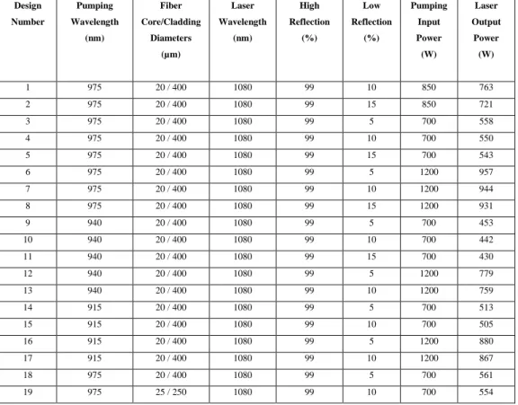
There are several parameters for all-fiber laser systems. By using these parameters, it is possible to obtain cavity. In order to achieve high power, those parameters are vital. Moreover, reflectivity of FBG, input power of diodes, pumping wavelength, fiber core/cladding diameters are the key features of high power laser systems. Each parameter plays a critical role in fiber laser. While determining those parameters, it is crucial to take into account the heating problems. Before designing the fiber laser we determined some parameter that can be used in fiber laser system. We put parameters in the RP Fiber Power software and run the programe. We obtained output powers for different cavity design. Those parameters are given in table 1.
Table 2. 1: The parameters for different type of fiber laser resonator
Design Number Pumping Wavelength (nm) Fiber Core/Cladding Diameters (µm) Laser Wavelength (nm) High Reflection (%) Low Reflection (%) Pumping Input Power (W) Laser Output Power (W) 1 975 20 / 400 1080 99 10 850 763 2 975 20 / 400 1080 99 15 850 721 3 975 20 / 400 1080 99 5 700 558 4 975 20 / 400 1080 99 10 700 550 5 975 20 / 400 1080 99 15 700 543 6 975 20 / 400 1080 99 5 1200 957 7 975 20 / 400 1080 99 10 1200 944 8 975 20 / 400 1080 99 15 1200 931 9 940 20 / 400 1080 99 5 700 453 10 940 20 / 400 1080 99 10 700 442 11 940 20 / 400 1080 99 15 700 430 12 940 20 / 400 1080 99 5 1200 779 13 940 20 / 400 1080 99 10 1200 759 14 915 20 / 400 1080 99 5 700 513 15 915 20 / 400 1080 99 10 700 505 16 915 20 / 400 1080 99 5 1200 880 17 915 20 / 400 1080 99 10 1200 867 18 975 20 / 400 1080 99 5 700 561 19 975 25 / 250 1080 99 10 700 554
30 20 975 25 / 250 1080 99 5 1200 1064 21 975 25 / 250 1080 99 10 1200 1064 22 940 25 / 250 1080 99 5 700 578 23 940 25 / 250 1080 99 10 700 574 24 940 25 / 250 1080 99 5 1200 991 25 940 25 / 250 1080 99 10 1200 984 26 915 25 / 250 1080 99 5 700 576 27 915 25 / 250 1080 99 10 700 563 28 915 25 / 250 1080 99 5 1200 973 29 915 25 / 250 1080 99 10 1200 966
We choose the design number 1. The design number 1 parameters were entered into the RP Fiber Power software simulations. According to the table… there are several options that we can choose. The parameters of design number 12 has higher pumping power. To achieve high power, pump power should be increased. The reflectivity of output coupler also can be decreased.The parameters of design number 15 are different than our system. According to literature if we choose design number 15, we should use longer active medium than the design number 1 to obtain 500 W output power. Below the results of RP simulations are given.
Figure 2. 1: Cavity design of fiber laser with RP simulation
Hence, the cavity design was performed according to this result. Active medium was composed of Yb3+ doped fiber and the active fiber length was 15.5 meters.
31
FBGs were selected with 99% high reflectivity and %10.4 low reflectivity. Also pump units were chosen at 975 nm wavelength and 135 W power.
Figure 2. 2: RP simulation of power vs position.
Figure 2. 3: Schematic of fiber laser resonator
After RP simulations, we started to integrate the components. We integrated diodes with combiner ports with no specific specialty.
Fiber ends should not have hackles, mists and cracks. Those failures cause bubble during the splicing process which is shown in fig. 2.4 Fibers also should
32
not cleave with an angle. In this case splicing process will be poor and power of light will be decreased.
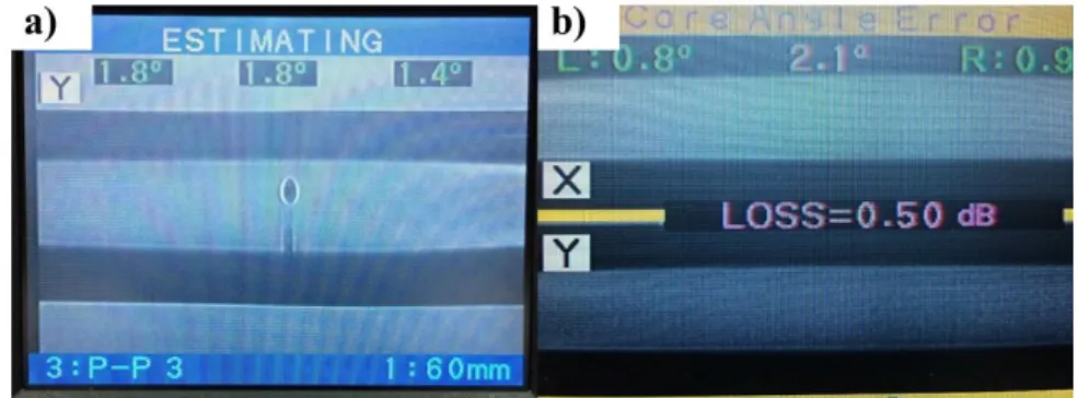
Figure 2. 4: Splice processes a) Bubble formation in splicing b) Mismatch of core angle in splicing
In fig. 2.4 a) 1.8˚ presents the cleave angle of left fiber and 1.4˚ presents the cleave angle of the right fiber. In the middle 1.8˚ presents the angle of fibers according to each other. In the case of cleaving fiber with hackles, mists, and cracks bubble forms which leads to power losses and eventually system will be compromises. In fig 2.4 b) 0.8˚ presents the cleave angle of the left fiber and 0.9˚ is the cleave angle of the right angle. In the middle 2.1˚ is the angle of the fibers according to each other. This value is too high for fiber laser systems. In the case of high core angle, system losses light which leads to decreasing of power.
Before the splicing of diode fibers with combiner fibers, we measured the output power of the all diodes which is given in fig 2.5
33
Figure 2. 5: The output power of all diodes.
Diode integrations were made successfully by considering all of those effects. Below fig 2.6, show the integration process of diode and combiner.
Figure 2. 6: Splicing process between diode fibers and combiner fibers
We made the splicing process between diode fiber and the combiner diodes. In fig 2.6 shows that the cleave angles are very low and the angles of diode and combiner fibers according to each other are very low. After splicing process we used optic power meter to measure the power of combined diodes.
34
Figure 2. 7: The output power of diodes after splicing with combiner
Due to the high power, we needed to cool the combiner. In order to cool the combiner, we designed a cooling unit. The cooling unit consists of many water channels and it has high temperature conductivity. It worked at low temperatures which is 17 ± 1˚C degree to overcome the heating of combiner. The designed unit is shown in fig 2.8 and 2.9. The cooling unit was designed in UNAM and fabricated by ERMAKSAN (Turkey).
Figure 2. 8: Design of the cooling plate for combiner
3
c
9
4
3
5
c
m
35
Figure 2. 9: The cooling plate for combiner(produced by Ermaksan)
The integration of combiner and the FBG (high reflective) was the next step of the project. We integrated these fibers accurately. In fig 2.10 combiner and the FBG splicing process is shown.
Figure 2. 10: Splicing process between combiner output fiber and the FBG fiber.
The most important step of splicing process is the splicing between active fiber and the FBG fiber since the active fiber geometry is different than the FBG fiber. The active fiber has octagonal cladding structure and the FBG has spherical structure. The loss must be very low to operate the system with quietly
36
reduced losses. In fig 2.11 is shown the end faces of the active fiber and the FBG fiber.
Figure 2. 11: The cross-section images of fibers
As it seen from the fig 2.11 fiber ends cleaved perpendicularly. There is no hackles, mists and cracks end face of the fibers. Hence we obtained appropriate fiber ends for integration process.
Figure 2. 12: The splicing process between FBG fiber and the active fiber
We then spliced the active fiber and the FBG (low reflective). The integration is shown in fig 2.13.
37
Figure 2. 13: Splice operation between FBG (low reflective) and the active fiber
In our system we used fusion splicing which is the most widely used splicing process. In this process, basically, arc hits the fibers while fibers are getting closer so that fibers become as a whole. It is a vital process for our fiber laser system. Splicing of the fibers must be done very without loss. Splice loss can be caused several factors such as coaxially, end face, mismatch of cores, concentricity, axial run out. It is directional with these variables. Furthermore, it can be minimized by aligning the fiber cores perfectly. After splicing process there must no bubbles, core mismatch. As it is mentioned, it compromises the laser system. There are several type of splicing processes.
2.2Characterization of equipments
In this study, we firstly characterized the diodes. In order to characterize the diodes, we needed to drive diodes with appropriate current and voltage values. Those values were indicated in data sheet of diodes. The diodes were driven one by one. Connections between drivers and diodes wereprovided as shown in fig 2.14.
38
Figure 2. 14: Connections between drivers and diodes
After making connections between diodes and drivers, we developed control panel. With the aid of control panel, six diodes, which are used in the project, were controlled by giving same voltage and ampere values. The control panel is given in fig 2.15. By this means, we concluded the part for the needed voltage and current for pumping units. Control panel was designed and fabricated in ERMAKSAN (Turkey).
39
The second important step is to control cooling of pumping units. Diodes produce high pumping power under high current, so it reveals heat generation. We controlled this situation by cooling them actively witha water-based system. For each pumping unit, the heating value was determined according to experimental results and cooled withcooling units. Cooling units worked between 20˚C-27˚C and has 2 bar pressure. Active cooling procedure was completed by integration of diodes and cooling units as shown in fig 2.16. In further steps we characterized diodes interms of optical spectrum and power and we determined the needed cooling values for diodes.
Figure 2. 16:Integration of diodes and cooling units
The next step was to prepare output fibers of diodes. This procedureconsisted of many stages. We need to prepare diode fibers with high quality. Fiber optic cables of diodes consist of a core and cladding, which covers core, and the cladding has higher refractive index than that of core. On top of the cladding, there is a fluoroacrylate polymer coating.First of all, we need to strip the coating polymer to prepare the diodes for integration process. After stripping the polymer coating from the surface of the fiber, it should be cleaned with isopropanol to remove any residual coating material.In cleaving process, one of
40
the substantial part is to obtain smooth end faces such ascleaving fibers without hackles, lips, cracks, chips and angle. If fiber end face is not cleaved properly, it causes problems such as back reflected light, which causes problems in the system, scattering of light, angled cleave causing gap between fibers splice operations, leading to ununiformed splice and light loss.
Figure 2. 17: Stripped fiber before cleaving
Progress for preparation of fibers is investigated by using optical microscope. For this investigation we used optical microscope and the resultis shown in fig 2.17. After we cleaved this fiber with fiber pen,the obtained fiber end was shown in fig 2.18 a). This fiber cannot be used for integration step. In fig 2.18 b)hackles, cracks, and chips on the surface of fiber end can be easily seen. If this fiber was integrated, we would see bubble on the spliced area and this causes light loss and eventually fiber would burn. Cleaving process was obtained properly by using automatic cleave machines. After cleaving fibers, we obtained surfaces as displayed in fig 2.18.
41
Figure 2. 18: a) Poor cleaving process b) Accurate cleaving process
After stripping and cleaving process, the end faces are cleaned with ultrasonic cleaner. After obtaining cleaved and cleaned surfaces, we characterized diodes. Each one of the diodes were cooled and driven individually. The driving currents and the optimum cooling temperatures of each individual diodes are given in Table 2.2. The equipments that we used for characterization are optic spectrum analyzer and power meter.
Table 2. 2: Parameters used for diodes
Diode Number Driving Voltage (V) Driving Current (A) İdeal Cooling Temperature at 975 nm Wavelength (˚C) 1 12 28 24 ± 1 2 12 28 22 ± 1 3 12 28 26 ± 1 4 12 28 26 ± 1 5 12 28 24 ± 1 6 12 28 22 ± 1
The figures between 2.19 and 2.30 represent the diode, power data of each diodes. In fig. Power of diodes were measured with Cohorent Power Max. The
![Figure 1. 1: Evolution of the average output power of fiber lasers [15]](https://thumb-eu.123doks.com/thumbv2/9libnet/5670939.113551/17.892.330.628.785.1028/figure-evolution-average-output-power-fiber-lasers.webp)

![Figure 1. 8: Light absorption of different type of double clad fibers [2]](https://thumb-eu.123doks.com/thumbv2/9libnet/5670939.113551/26.892.273.672.205.506/figure-light-absorption-different-type-double-clad-fibers.webp)
![Figure 1. 9 :Bending loss as a function of bending radius for SM, SI and LMA fibers [30]](https://thumb-eu.123doks.com/thumbv2/9libnet/5670939.113551/27.892.324.609.544.770/figure-bending-loss-function-bending-radius-lma-fibers.webp)
![Figure 1. 11: Absorption and emission cross-sections of Yb-doped fibers [34]](https://thumb-eu.123doks.com/thumbv2/9libnet/5670939.113551/34.892.256.701.510.755/figure-absorption-emission-cross-sections-yb-doped-fibers.webp)